
You’ll need heavy-duty rectifiers in diesel-electric locomotives because they convert the main alternator’s three-phase AC output into stable DC power for your traction motors. These robust systems handle continuous electrical loads exceeding 3,000 amperes while withstanding extreme temperatures from -40°F to 185°F and severe mechanical vibrations. They enable precise speed and torque control across multiple motors simultaneously, ensuring consistent power delivery during dynamic load changes. Understanding their complete integration reveals why they’re absolutely critical for locomotive performance.
Key Takeaways
- Rectifiers convert the alternator’s three-phase AC output to stable DC power required for precise traction motor control and operation.
- Locomotives demand continuous power conversion up to 3,000 kW with currents exceeding 3,000 amperes during peak operational scenarios.
- Heavy-duty rectifiers withstand extreme temperatures (-40°F to 185°F), vibration loads exceeding 5G, and harsh environmental conditions including diesel exhaust.
- Rectifiers enable coordinated power distribution to four or six traction motors simultaneously while maintaining consistent torque output around 60,000 lb-ft.
- Solid-state rectifier technology provides superior reliability and ruggedness compared to mechanical alternatives while supporting advanced electronic control systems.
Converting AC Power to DC for Optimal Traction Motor Control

Within the heart of every diesel-electric locomotive, the main alternator converts the diesel engine’s rotational energy into three-phase AC power, but this raw electrical output can’t directly control traction motors with the precision modern rail operations demand. You’ll find that heavy-duty rectifiers function as electrical check valves, converting this AC power into pulsating DC through full-wave rectification. This process captures both positive and negative sine wave alternations, eliminating AC’s 60-times-per-second directional reversals.
The resulting DC power provides superior speed and torque control compared to AC systems. You’re able to achieve precise starting torque characteristics essential for heavy freight applications. Modern solid-state rectifiers integrate with synchronous excitation systems and support regenerative braking capabilities, allowing energy recovery during deceleration. These rectifier banks handle extreme electrical stresses while maintaining continuous operation under harsh railway conditions, directly impacting your locomotive’s overall efficiency and performance. The circuit breakers integrated within these systems provide critical protection against electrical overloads that could damage expensive traction motor components.
Managing High-Current Electrical Loads in Railway Operations

When you’re operating diesel-electric locomotives, you’ll encounter continuous high-power demands that can reach 3,000 kW, requiring rectifiers capable of handling sustained electrical loads without thermal failure. Your traction motors draw massive current levels that vary constantly based on speed and load conditions, making precise current management critical for preventing motor damage. You’ll need robust multi-motor load distribution systems that can regulate power flow to four or six traction motors simultaneously while maintaining stable performance under extreme operational conditions. The diesel engine’s mechanical energy must be efficiently converted through the alternator to meet these demanding electrical requirements while supporting both propulsion and auxiliary systems.
Continuous High-Power Demands
As diesel-electric locomotives traverse thousands of miles under continuous operation, their rectifier systems must handle sustained high-current electrical loads that can exceed 3,000 amperes during peak performance scenarios. You’ll find these heavy-duty rectifiers processing continuous power conversion from diesel generators rated between 2000-4000 HP throughout extended railway journeys. The constant electrical flow creates significant thermal fatigue within power electronics components, requiring robust cooling systems and advanced materials.
Your locomotive’s rectifier system experiences demanding duty cycling as it alternates between acceleration, grade climbing, and heavy cargo transport. This continuous service generates thermal stress from frequent load variations, making standard rectifiers inadequate. Heavy-duty rectifiers incorporate IGBT modules and SiC power electronics to maintain consistent voltage levels while managing the thermal cycling inherent in railway operations. Modern locomotives integrate digital technologies to enable real-time monitoring of rectifier performance and reduce operational downtime.
Multi-Motor Load Distribution
Beyond sustaining continuous power conversion, heavy-duty rectifiers must efficiently manage the complex distribution of electrical loads across multiple traction motors that can draw up to 4,700 amperes collectively. You’re dealing with sophisticated power distribution systems that accommodate varying motor requirements caused by axle imbalance from different driving wheel weights. Your rectifiers coordinate with electronic control systems to maintain consistent total traction torque across all motors, delivering approximately 60,000 lb-ft of combined force.
When operating conditions prevent individual motors from delivering designed output, you’ll need torque redistribution capabilities. Your load regulation systems continuously monitor real-time demands, adjusting generator output while preventing wheel slip through precise power delivery modulation. The compression ignition diesel engine provides the reliable mechanical energy foundation that powers the entire electrical generation system. Advanced predictive algorithms enable preemptive load distribution adjustments, maximizing fuel efficiency by matching generator output to actual distributed power needs across multiple coordinated traction motors.
Solid-State Rectification Technology for Enhanced Performance

Since EMD’s introduction of the AR10 Alternator Rectifier system in 1966, solid-state silicon diode technology has revolutionized locomotive power conversion by delivering superior performance characteristics that mechanical systems couldn’t match. You’ll find that silicon reliability guarantees consistent operation despite harsh vibrations and temperature extremes encountered in locomotive environments. The diode ruggedness withstands demanding operational conditions while maintaining voltage drops of only fractions of a volt through the rectifier.
You’re benefiting from full-wave rectification that converts AC sine waves to pulsating DC, enabling precise motor speed and torque control. The technology eliminates shifting requirements, improving overall system reliability while providing faster response times than mechanical switching. External mounting on traction alternators gives you accessible maintenance access, reducing downtime.
Modern rectifiers expand alternator output capacity beyond previous limitations, delivering consistent power regardless of engine speed variations. You’ll experience optimized efficiency through advanced electronic control systems that regulate power flow across varying operational demands. Heavy-duty rectifiers handle the substantial current loads required by DC traction motors that provide the high starting torque essential for locomotive operation.
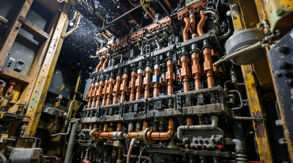
Strategic Placement and Physical Integration Within Locomotive Systems

You’ll find rectifiers strategically positioned in auxiliary cab sections where they’re protected from operational hazards while maintaining ideal access to high-voltage distribution networks. The placement directly influences high-voltage cable routing efficiency, as shorter runs between alternators and traction motors reduce power losses and improve system response times. Your locomotive’s cooling system integration becomes critical at this junction, since rectifier positioning must balance thermal management requirements with the need for environmental protection of sensitive solid-state components. These rectifiers must handle the conversion from AC to DC while managing electrical faults through integrated protective devices that safeguard the entire power distribution system.
Auxiliary Cab Positioning
Strategic placement of auxiliary cab components hinges on achieving peak integration between operator accessibility and system performance requirements. You’ll find NSW signalling standards mandate left hand seating configuration with observer placement on the right side during forward travel. This positioning optimizes your access to angled control stands preferred by operators over European desk-type layouts. You can effectively manage diesel engine controls and electrical systems through this strategic arrangement.
The auxiliary generator’s voltage regulator sits in the upper left corner of equipment cabinets, while electronic controls cluster near the cab for maintenance accessibility. Single cab configurations work in US structure gauge environments, but you’ll need dual control stands for narrow body locomotives requiring bidirectional operation, each oriented for left-hand running.
Modern locomotives utilize hydraulic governance systems alongside electronic controls to ensure optimal engine speed regulation for varying power demands. This integration allows for precise coordination between the auxiliary cab positioning and the engine control mechanisms that maintain appropriate performance levels across different operational scenarios.
High-Voltage Cable Routing
Mapping out high-voltage cable pathways demands precise coordination between electrical safety requirements and mechanical constraints within locomotive systems. You’ll need to establish dedicated conduit segregation for 2000V maximum power leads, keeping them isolated from auxiliary circuits to prevent electromagnetic interference. Your DLO cables require stranded tinned copper conductors with EPR insulation and CPE construction for optimal jacket durability in harsh locomotive environments.
You must route these cables through independent pathways connecting traction motors to rectifier assemblies. The +90°C temperature rating ensures reliable operation in engine compartments, while UL Type RHH/RHW-2 approvals maintain safety compliance. Your cable management system should accommodate both fixed installations and flexible locomotive movement, utilizing organized raceway systems that protect against mechanical damage while maintaining proper voltage separation throughout the entire diesel-electric power distribution network. Modern compact power electronics have simplified the construction requirements for these high-voltage routing systems, reducing space constraints while improving overall reliability.
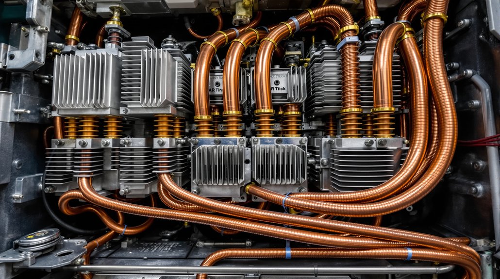
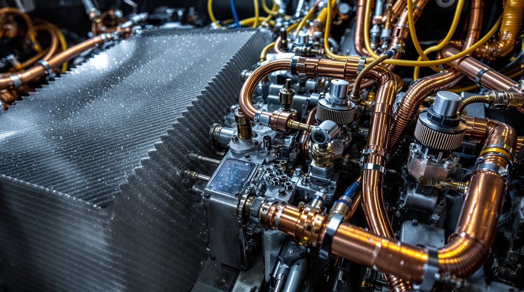
Cooling System Protection
When rectifier assemblies convert high-voltage AC power to DC within your locomotive’s electrical system, they generate substantial heat that demands strategic cooling integration to prevent thermal failures. Your cooling system must effectively manage temperatures across multiple heat sources while maintaining peak performance.
Critical cooling protection components include:
• Coolant routing circuits that connect rectifier assemblies to main radiator networks
- Thermostat calibration systems that regulate flow based on thermal load requirements
- Thermal overload sensors monitoring ambient inlet air and component temperatures
- Water pumps circulating 265-530 gallons through integrated cooling networks
- Circuit breaker integration preventing electrical overloads that generate excessive heat
- Your locomotive’s thermal protection calculates traction motor current limits using temperature data, ensuring rectifiers operate within safe parameters while maintaining constant horsepower output during demanding operations. Proper coolant formulations with corrosion inhibitors create protective films that safeguard rectifier housing and heat exchanger metal surfaces from rust and chemical damage.
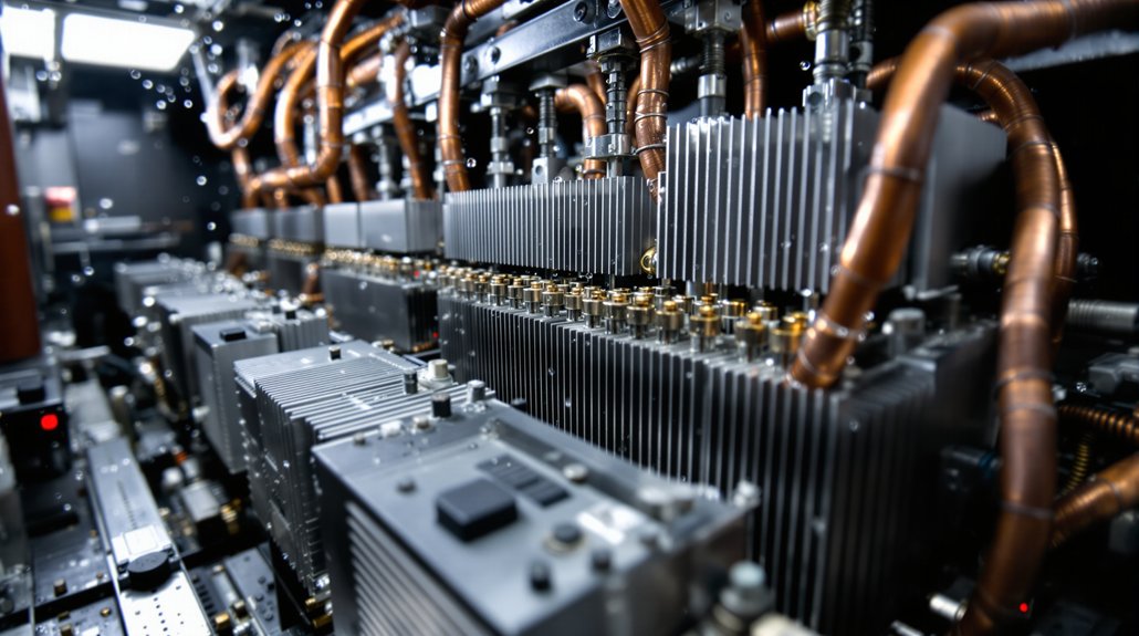
- Withstanding Environmental Stresses and Operational Vibrations
- Operating in harsh railroad environments, heavy-duty rectifiers must endure extreme temperature fluctuations ranging from -40°F to 185°F while maintaining precise voltage conversion performance. You’ll find these components undergo rigorous environmental qualification protocols that test moisture resistance, dust ingress protection, and thermal cycling endurance. The rectifiers face constant mechanical stress from track irregularities, coupling forces, and engine vibrations that can exceed 5G acceleration loads.
- Your locomotive’s rectifier assemblies require specialized vibration testing to validate structural integrity under continuous operational stresses. The mounting systems incorporate shock-absorbing materials and reinforced housing designs that prevent component fatigue and electrical connection failures. You’re dealing with power electronics that must function reliably despite exposure to diesel exhaust, corrosive elements, and electromagnetic interference from traction motors. These environmental challenges demand robust semiconductor packaging, conformal coatings, and hermetic sealing techniques that guarantee consistent electrical performance throughout extended service intervals. Modern diesel-electric locomotives have evolved significantly since the early 20th century when various countries first introduced these revolutionary rail vehicles.
- Maximizing Energy Efficiency Through Advanced Power Conversion
- Through sophisticated power conversion technologies, diesel-electric locomotives transform raw fuel energy into precisely controlled electrical output with remarkable efficiency gains that you’ll find essential for modern rail operations.
- Advanced rectifier systems enable diesel-electric locomotives to achieve substantial energy improvements through optimized conversion processes. You’ll benefit from these efficiency-maximizing technologies:
- Dynamic braking recovery – Captures 12-33% of operational energy through regenerative strategies during deceleration phases
- Waste heat utilization – Recovers up to 437.6 kW from exhaust gas thermal optimization, representing 18% of maximum engine power
- Precision power management – Controls timing and delivery of electrical energy to traction motors with minimal conversion losses
- Advanced rectification – Converts AC to DC electricity while reducing mechanical component wear through efficient power handling
- Integrated electronics – Adapts power delivery based on operational demands for peak performance across varying conditions
- These systems deliver $54,000 to $140,000 annual fuel savings per locomotive while maintaining the robust power conversion capabilities essential for heavy-duty rail operations.
- Supporting Multiple Traction Motors Across Locomotive Configurations
- Scaling up from single motor operations, diesel-electric locomotives distribute power across multiple traction motors through sophisticated rectifier systems that must handle the full electrical load of the entire propulsion system. You’ll find that heavy-duty rectifier banks process the complete alternator output before distribution, creating modular scalability that adapts to different locomotive configurations. Multiple rectifier units work together, establishing redundant pathways that guarantee reliable power delivery even if individual components fail.
- Your locomotive’s electrical architecture varies by manufacturer—GM uses one inverter per truck while GE employs one inverter per motor. Each inverter contains six gated turn-on devices and high-power thyristors that manage power flow to individual traction motors. The rectification stage precedes these inverter systems, smoothing uneven alternator output into stable DC power. This coordinated approach eliminates external power supply dependencies while supporting simultaneous motor operation across the entire locomotive fleet.
- Integration With Modern Electronic Control and Monitoring Systems
- Modern diesel-electric locomotives integrate sophisticated electronic control systems that continuously monitor and regulate rectifier performance across all operational parameters. These microprocessor-based controllers deliver precise voltage and current regulation while providing real time diagnostics for peak power conversion efficiency.
- Advanced solid-state rectifier technology incorporates intelligent monitoring capabilities that track critical performance metrics:
- Temperature monitoring and thermal management across semiconductor components
- Current load analysis with automatic compensation for varying electrical demands
- Conversion efficiency tracking with integrated feedback loop adjustments
- Fault detection algorithms that enable predictive maintenance scheduling
- Harmonic reduction control through precise switching frequency management
- You’ll find these control systems automatically adjust rectifier operations during dynamic load changes, ensuring consistent power delivery to traction motors. The integrated diagnostic capabilities detect potential failures before they occur, reducing downtime and maintenance costs. Electronic protection algorithms coordinate with circuit breakers to isolate faults instantly, maintaining system integrity while maximizing locomotive performance under demanding operational conditions.
Frequently Asked Questions
- How Much Do Heavy-Duty Rectifiers Cost Compared to Standard Electrical Components?
- Like Hercules bearing Atlas’s burden, you’ll find heavy-duty rectifiers commanding premium pricing over standard components. Your material costs escalate markedly—locomotive rectifiers range $15,000-$45,000 versus $500-$2,000 for standard units. However, your lifecycle pricing analysis reveals compelling economics: heavy-duty systems deliver 20-year operational lifespans with minimal degradation, while standard components require frequent replacement. You’re investing in robust silicon-controlled rectifier technology that withstands extreme thermal cycling and vibration demands.
- What Happens When a Rectifier Fails During Locomotive Operation?
- When your rectifier fails, you’ll experience immediate power conversion disruption that cuts DC electricity flow to traction motors. Your locomotive loses consistent power supply, causing reduced mechanical output and potential engine stall. You’ll face irregular voltage distribution throughout electrical systems, leading to axle overheating from uneven power delivery. Complete operational shutdown occurs as your engine control systems can’t manage power timing effectively.
- How Often Do Heavy-Duty Rectifiers Require Replacement or Major Maintenance?
- “An ounce of prevention’s worth a pound of cure” applies perfectly to rectifier maintenance. You’ll need diode replacements every 15,000-25,000 hours, while complete module overhauls occur every 50,000-75,000 hours. Service intervals tighten to 500-750 hours under high-amperage conditions. Monitor forward voltage drops and harmonic distortion levels—these failure modes signal imminent replacement needs. Environmental factors reduce standard intervals by 20-30%, demanding vigilant condition-based monitoring.
- Can Older Locomotives Be Retrofitted With Modern Solid-State Rectifier Systems?
- You can retrofit older locomotives with modern solid-state rectifier systems, though legacy compatibility requires careful evaluation of existing electrical infrastructure. Installation challenges include adapting mounting configurations, upgrading control systems, and ensuring proper integration with original traction motors. You’ll need to modify wiring harnesses and potentially replace associated power electronics components. These retrofits deliver significant performance improvements, extending locomotive service life by 25 years while achieving substantial efficiency gains.
- Do Different Locomotive Manufacturers Use Compatible Rectifier Technologies?
- You’ll find that different locomotive manufacturers don’t use compatible rectifier technologies despite similar functional requirements. While EMD, GE, and other builders all adopted solid-state rectification by the mid-1960s, manufacturer compatibility remains limited due to proprietary designs. Each company developed distinct technology standards for voltage ratings, cooling systems, and control interfaces. You can’t easily interchange rectifier units between EMD and GE locomotives without significant electrical system modifications.