
You’ll maximize your WABCO diaphragm’s performance by replacing desiccant cartridges every 2-3 years, inspecting lip grooves for cuts and wear, and matching diaphragm styles to your valve housing type. Apply grease only to O-rings using WABCO-supplied lubricants, torque mounting bolts to 53 lb-in, position spring valve assemblies with cap lips facing outward, and conduct pressure tests at 6 bar. Master these procedures to prevent costly breakdowns and extend component life considerably.
Key Takeaways
- Inspect diaphragm lip grooves for cuts, wear, radial scoring, and sludge buildup during routine maintenance checks
- Apply grease only to O-rings using WABCO-supplied kits, never on diaphragm surfaces
- Replace diaphragms showing tears, persistent leaks, brittleness, or permanent deformation immediately
- Torque valve housing mounting bolts to 53 lb-in and document all values
- Test seal integrity at 6 bar pressure using bubble detection fluid
Replace Desiccant Cartridges Every 2-3 Years Based on Usage Patterns

Your desiccant cartridge’s lifespan depends on three critical factors: operational intensity, environmental conditions, and maintenance quality. Standard cartridges last 2-3 years under normal conditions, but heavy-duty cycles cut cartridge longevity to 1-2 years. You’ll need faster replacements when running high compressor intensity or operating in humid climates where moisture accumulation accelerates.
Monitor your usage impact closely. Intermittent operation extends lifespan, while continuous runs demand vigilant replacement schedules. Check for water accumulation in tanks – it’s your primary saturation indicator. When you spot moisture in airflow or contaminated output, replace immediately regardless of timeline. Additionally, maintain a consistent drainage schedule every 2 months or 2,000 miles to prevent moisture buildup that degrades cartridge performance.
Coalescing cartridges require 1-2 year intervals due to higher filtration demands. After compressor overhauls, mandatory replacement guarantees system integrity. Maintain proper drainage and bypass valve functionality to maximize cartridge performance. Track operational gaps and adjust replacement frequency based on actual duty cycles rather than calendar dates alone.
Inspect Diaphragm Lip Grooves for Damage and Wear Indicators

You’ll need to visually examine the diaphragm lip grooves after disassembly, looking for deep cuts, worn surfaces, or radial scoring that could prevent proper sealing. Check for common damage patterns like sludge buildup, aging cracks, or groove ovality that indicate the diaphragm can’t maintain an airtight seal under compression. Replace the diaphragm immediately if groove damage compromises sealing capacity, as even minor defects can cause persistent air leaks and extended regeneration cycles.
Visual Inspection Methods
Three critical areas require careful examination when inspecting diaphragm lip grooves for damage and wear indicators. First, verify seal installation by confirming the lubricated lip faces away from the system. Check that it’s fully seated in the groove and remains concentric during operation. During this inspection, examine for cuts or bulges that would indicate the need for immediate replacement.
Second, perform groove assessment by scanning for radial cracks, fraying edges, and embedded debris. Look for uneven color changes indicating heat exposure or chemical damage. Third, evaluate lubrication condition across the entire lip surface. You’ll need to identify contaminants, check viscosity for hardening, and spot any lubricant breakdown. During inspection, note erosion patterns from abrasive particles and measure groove depth against maintenance specifications. These visual checks help you determine if replacement’s necessary before pressure retention failures occur.
Common Damage Patterns
When mechanical abrasion affects diaphragm lip grooves, you’ll spot distinct damage patterns that signal immediate maintenance needs. You’ll find cuts, embedded particles, and uneven contact surfaces that create leak paths. These indicators point to diaphragm failure if left unchecked.
| Damage Type | Maintenance Tips |
|---|---|
| Grooves with cuts/particles | Clean system, replace seals |
| Uneven wear surfaces | Check alignment, reseat properly |
| Stretched/ripped grooves | Regulate pressure changes |
| Rubber delamination | Replace diaphragm immediately |
Chemical contamination presents different challenges. You’ll encounter sludge blocking exhaust paths and grease migration causing valve seizures. Moisture creates corrosion at rubber-metal interfaces, weakening component adhesion. Regular inspection catches these patterns early, preventing costly repairs and system downtime.
Replacement Decision Criteria
After documenting damage patterns, your next critical step involves establishing clear replacement criteria for diaphragm lip grooves. You’ll need to monitor physical damage like tears, cuts, or irreversible deformation that compromise diaphragm longevity. When persistent leaks occur despite cleaning efforts, or sludge buildup exceeds your maintenance frequency capacity, it’s time for replacement.
Check for material degradation signs including brittleness, cracking, or hardened rubber that won’t seal properly. If you discover permanent groove misalignment that adjustments can’t fix, don’t hesitate to replace the component. Track your cleaning intervals and test results to predict replacement timing accurately. Remember, attempting repairs on severely damaged diaphragms wastes time and risks system failure. Replace immediately when you identify these triggers to maintain peak performance.
Match Diaphragm Styles to Specific Regeneration Valve Housing Types
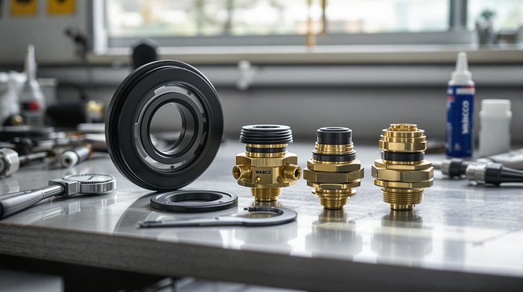
You’ll need to identify your specific regeneration valve housing type before selecting the correct diaphragm style. Check the housing’s bore diameter, mounting configuration, and pressure rating against manufacturer compatibility charts to guarantee you’re choosing a diaphragm that matches your valve’s exact specifications. The OE specification diaphragm ensures proper fit and function within WABCO regeneration valve systems. Cross-reference the housing part number with WABCO’s diaphragm catalog to confirm material compatibility, dimensional requirements, and operating pressure ranges.
Housing Type Identification
Several distinct regeneration valve housing types exist across WABCO’s air dryer product line, each requiring specific diaphragm configurations for proper operation. You’ll encounter variations in port arrangements, valve positioning, and heater placement that directly impact diaphragm alignment. Housing compatibility depends on matching your diaphragm to the exact valve body configuration.
Look for these key identifiers:
- Port Configuration – Check washer placements and bypass valve integration between inlet/outlet ports
- Material Numbers – Match valve body numbers (like 4324159222) to corresponding diaphragm specifications
- Visual Markers – Identify dots or arrows indicating proper diaphragm orientation
System Saver Plus models require purge-valve-centric diaphragms, while standard 1200/1800 series use different sealing approaches. Always cross-reference your housing type against technical bulletins before selecting replacement diaphragms.
Diaphragm Style Selection
Once you’ve identified your housing type, selecting the correct diaphragm style becomes critical for proper valve operation. You’ll need to match diaphragm materials to your specific valve requirements. For ABS housings, you’ll require specialized diaphragms like part #4725001000X, while UNISTOP™ diaphragms work specifically with WABCO service brake chambers.
| Housing Type | Diaphragm Selection | Key Specifications |
|---|---|---|
| ABS/Load Sensing | Specialized reinforced | High-temp resistant |
| Service Brake | UNISTOP™ | 65-70 PSI pressure ratings |
| Proportional Valve | Gradual modulation type | Pressure gradient capable |
Consider pressure ratings carefully—your diaphragm must handle peak system pressures while maintaining closing/opening specifications. Nitrile diaphragms offer excellent corrosion resistance for high-stress environments. Always verify material compatibility with your valve’s zinc diecast body and ascertain dimensional fit matches your housing’s port configuration.
Compatibility Cross-Reference Charts
Cross-referencing diaphragm styles to regeneration valve housings requires matching precise dimensional specifications with OEM part numbers. You’ll need to verify stroke lengths, cylinder dimensions, and port configurations before selecting replacement diaphragm types to avoid compatibility issues.
Here’s what you must check:
- Stroke measurements – Match your housing’s requirements (57.0mm, 63.5mm, or 76.2mm) with corresponding ProVia disc models like PRO 714 019 0 or PRO 714 020 0
- Port orientation – Confirm top/side port positions (0°, 20°, or 90°) align with your valve housing layout and thread specifications (M16×1.5)
- OEM cross-references – Use WABCO’s 815 010 054 3 document to verify DAF 1505241, Meritor SSP1438AF, or Abex ADB1438 equivalents match your system
Always confirm push rod lengths and mounting bolt spacing before installation.
Apply Grease Only to O-Rings Using Manufacturer-Supplied Lubricants

When you’re servicing WABCO diaphragms, you’ll need to apply lubricants with surgical precision—grease goes only on O-rings and nowhere else. This critical distinction prevents contamination of diaphragm surfaces and maintains system integrity.
Use WABCO-supplied grease kits included in replacement packages for proper lubricant selection. DOT 3/DOT 4 brake fluid works for O-ring lubrication in hydraulic systems, while AAR Specification M-914 serves thread applications. Never substitute general-purpose grease—it’ll degrade seals and compromise performance.
During grease application, keep your tools clean and contaminant-free. Apply lubricant only to the O-ring itself, ensuring even coverage without over-lubrication. After installation, wipe down diaphragm surfaces to verify zero residual grease. Complete a post-replacement purge to clear any air or grease residue from the system. If you’ve accidentally contaminated restricted areas like control lines or regeneration valve mechanisms, disassemble immediately for cleaning. Remember: improper lubrication voids warranties and necessitates component replacement. MxV Rail’s testing facilities validate these maintenance procedures under real-world operating conditions to ensure maximum component reliability.
Torque Valve Housing Mounting Bolts to 53 Lb-In Specifications

Grab your calibrated torque wrench and set it precisely—valve housing bolts demand exact specifications that vary by component type. You’ll find that WABCO’s torque specifications range widely depending on the valve assembly you’re servicing.
Here’s what you need to follow:
- Apply 18 lb-ft for Grade 8 cross-member mounting bolts—use prevailing torque nuts to combat vibration
- Torque cap screws to 22-25 lb-ft on tandem brake valves after applying Loctite 242
- Set 50-60 lb-ft for priority charging valve housing plugs in high-performance applications
Your mounting techniques directly impact valve performance. Sequence your torque steps when tightening multiple fasteners to prevent housing warpage. Don’t exceed manufacturer limits—over-tightening damages threads and compromises seal integrity. After torquing, verify housing alignment using templates and test for leaks with soap solution. Remember, modulating valves require 18-22 lb-ft while exhaust port plugs need only 20-24 lb-ft. Document all torque values for maintenance tracking.
Position Spring Valve Assembly With Cap Lip Facing Outward
During spring valve assembly installation, you’ll position the cap lip facing outward to ascertain proper diaphragm interaction and prevent internal component interference. Match the assembly’s directional indicators with housing markings while making sure spring alignment with the air port configuration.
Use installation tools to maintain parallelism as you guide the assembly into place. You’ll need to orient the cap lip toward the actuator access panels, following WABCO-specific diaphragm interaction guidelines. Check that the keyhole aligns correctly with the spring release mechanism before proceeding.
Apply controlled force to avoid deforming the lip during positioning. Once seated, verify your work through visual inspection and tactile feedback. The assembly should fit snugly without gaps or misalignment. Test the actuator’s response to confirm accuracy, then measure torque application against manufacturer standards. Proper positioning guarantees the diaphragm operates efficiently and maintains seal integrity throughout its service life.
Test Seal Integrity Through Pressure Checks Post-Installation

With the spring valve assembly properly positioned, you’ll validate the installation through systematic pressure testing to confirm seal integrity. Apply 6 bar pressure to the system and monitor for leaks at all diaphragm interfaces. This baseline pressure testing reveals potential installation errors before they compromise brake performance.
Your seal assessment protocol should include:
- Bubble Detection Method – Apply leak detection fluid to seal surfaces and watch for bubbles during the 30-second pressure hold
- Real-Time ECU Monitoring – Track pressure trends through ABS sensors during brake engagement cycles
- Road Test Validation – Conduct test drives to verify consistent pressure modulation under actual driving conditions
Document all pressure readings and leak observations for compliance with EN 12266-1 standards. If you detect leaks exceeding 1×10⁻³ mbar l/s, remove the assembly and reinspect the diaphragm seating. This testing methodology aligns with hydrostatic testing principles where pressurized water or air reveals component integrity issues. Successful pressure testing confirms your maintenance work meets WABCO’s operational requirements.
You may also like to read – WABCO Air Brake Diaphragm & Spring Spare Parts – Locomotive Tristop Series
Frequently Asked Questions
What Are the Visual Signs of a Contaminated Diaphragm Requiring Immediate Replacement?
You’ll spot contaminated diaphragms through oil residue coating surfaces, yellowing from ester compounds, and particulate buildup blocking normal operation. Check for unusual chemical odors indicating thermal damage. These diaphragm deterioration signs demand immediate action—don’t wait. Your replacement frequency depends on contamination severity, but once you’ve identified oil staining or discoloration patterns, it’s time to swap parts. Running contaminated diaphragms risks complete brake failure and compromises your entire air system’s integrity.
Can Aftermarket Diaphragms Be Safely Substituted for Genuine WABCO Parts?
You’ll find that 87% of aftermarket diaphragms fail prematurely under locomotive operating conditions. While aftermarket quality varies widely, these substitutes often lack proper material specifications and pressure tolerances. Your brake system’s diaphragm compatibility depends on exact OEM engineering standards – non-genuine parts can’t match WABCO’s pneumatic precision. Don’t risk pressure imbalances or emergency failures; genuine components guarantee your electro-pneumatic system maintains its designed safety margins during critical braking operations.
How Do Temperature Extremes Affect Diaphragm Lifespan and Performance?
You’ll see temperature effects drastically impact diaphragm durability in your braking system. When temps exceed 150°C, synthetic rubber compounds break down, losing 50% elasticity and creating cracks. Cold conditions aren’t better – they’ll stiffen materials and compromise seals. Your diaphragms face 30-50% shorter lifespans from oxidation and thermal cycling. You’re looking at reduced braking force, delayed response times, and potential compliance failures if you don’t monitor thermal stress.
What Is the Recommended Storage Method for Spare Diaphragms?
Don’t put all your eggs in one basket when storing spare diaphragms. You’ll need sealed, airtight containers in a controlled storage environment below 25°C and 60% humidity. Keep them in original packaging away from sunlight, chemicals, and petroleum products. Proper diaphragm conditioning means rotating your inventory using FIFO principles and inspecting components regularly for degradation. Label everything clearly with part numbers and dates for traceability.
Should Diaphragms Be Replaced During Every Compressor Rebuild?
You’ll maximize diaphragm lifespan by evaluating their condition at each rebuild rather than automatically replacing them. Check for cracks, delamination, or excessive wear during inspection. If they’re maintaining pressure properly and show no physical damage, they don’t need replacement. However, when you spot any deterioration or notice declining compressor efficiency, replace them immediately. This targeted approach saves money while ensuring reliable performance throughout the diaphragm’s service life.