Welcome to Mikura International’s comprehensive guide on WABCO air compressor head gasket kits, specifically the 85mm variant, essential for maintaining the optimal performance of your locomotive’s air system. As a leading exporter of locomotive and marine engine parts, we understand the critical role these components play. This guide is designed for experts seeking to source reliable spare parts and gain deeper insights into their applications and maintenance.
Understanding the WABCO Air Compressor in Locomotives

The WABCO air compressor is a vital component in locomotive braking and auxiliary systems. It delivers the compressed air necessary for operating brakes, horns, and other pneumatic devices throughout the locomotive. These robust air compressors are designed for continuous operation in demanding environments, making them a standard in the rail industry. Regular maintenance and timely replacement of parts, such as the head gasket, are crucial for reliable performance.
What is a WABCO Air Compressor?
A WABCO air compressor is a reciprocating compressor designed to supply compressed air for various pneumatic systems on a locomotive. These compressors often come in single or twin cylinder configurations, depending on the air demand of the locomotive. The WABCO air compressor system includes a crankcase, cylinder, compressor head, and other critical parts. The robust design ensures durability and a consistent air supply, vital for safe and efficient train operation. Mikura International offers a wide range of WABCO catalog parts to keep your compressors running smoothly.
Key Components of the Compressor
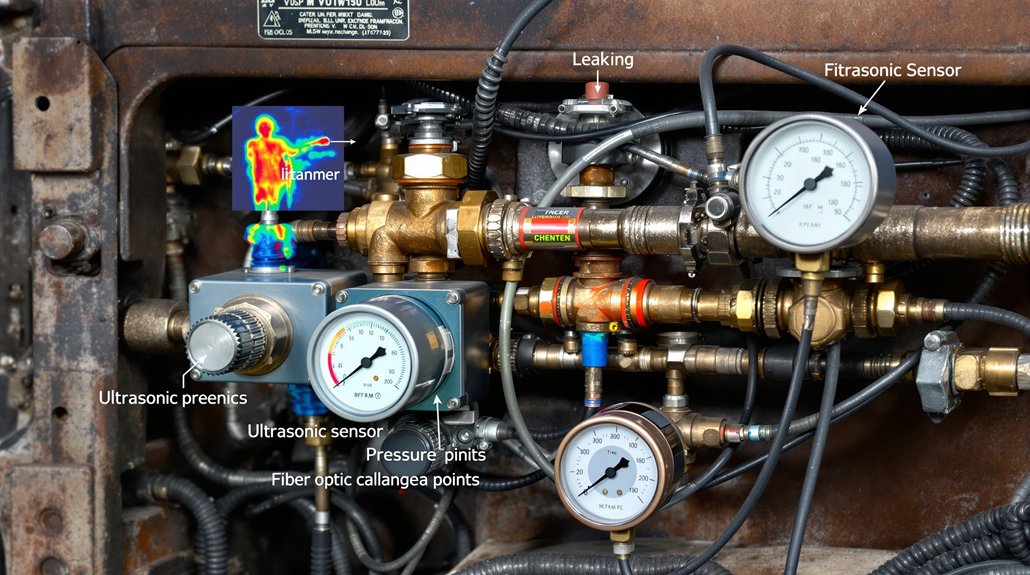
The WABCO air compressor comprises several key components, including the cylinder, compressor head, crankcase, pistons, and valves. Crucial to its operation are the following elements:
- The head gasket, which seals the cylinder head to the engine block, preventing air leakage and maintaining optimal compression.
- The cylinder, where the air is compressed.
- The compressor head, which houses the valves.
- The crankcase, which supports the mechanical components.
Mikura International supplies original and new WABCO parts with material numbers for reliable repairs.
Importance of the Head Gasket in Locomotive Applications
The head gasket is a critical sealing component in the WABCO air compressor, preventing leakage of compressed air from the cylinder. It ensures that the air compressor maintains the necessary pressure for the locomotive’s braking and auxiliary systems to function correctly. A faulty head gasket can lead to reduced compressor efficiency, increased fuel consumption, and potential system failures. Mikura International offers a WABCO 85mm head gasket kit made with a high-quality gasket by WABCO with material, ensuring a reliable and long-lasting seal during installation.
Features of the 85mm Head Gasket Kit

Specifications of the 85mm Gasket Kit
The WABCO 85mm head gasket kit from Mikura International features precise dimensions, adhering to the WABCO catalog specifications for optimal fit. The 85mm size refers to the inner diameter of the gasket, ensuring a perfect seal for compatible WABCO air compressor models. The kit includes a high-quality gasket, crafted with durable materials like reinforced steel and rubber compounds to withstand high pressures and temperatures. This ensures reliable performance and longevity of the air compressor.
Benefits of Using the WABCO Gasket Kit
Using the WABCO 85mm head gasket kit offers several benefits, especially in maintaining the air compressor’s efficiency. A new head gasket ensures a tight seal, preventing air leaks and maintaining optimal pressure within the cylinder. This, in turn, improves the performance of the locomotive’s braking and auxiliary systems. The kit from Mikura International helps reduce downtime and maintenance costs by providing a reliable, long-lasting solution. It guarantees that your WABCO air compressor operates at peak efficiency.
Comparative Analysis of Different Kits
When comparing different head gasket kits, it’s essential to consider the material, precision, and compatibility with your specific WABCO air compressor model. Mikura International’s WABCO 85mm head gasket kit stands out due to its high-quality construction and adherence to WABCO specifications with material numbers. Cheaper alternatives may use inferior materials, leading to premature failure and increased maintenance. Our kit ensures a reliable seal and optimal performance. It also comes with a warranty that ensures the quality.
Installation Guide for the Air Compressor Head Gasket

Tools and Materials Needed for Installation
Before starting the installation of the air compressor head gasket, gather the necessary tools and materials. This includes a variety of items:
- A socket set and wrench set, along with a torque wrench.
- A scraper and cleaning solvent.
- The new WABCO 85mm head gasket kit from Mikura International.
Make sure to have safety glasses and gloves to protect yourself during the process. Having a WABCO inform catalog handy can help in confirming parts, especially if working on older compressor models.
Step-by-Step Installation Process
The installation process starts with disconnecting the air supply to the WABCO air compressor. Then, remove the compressor head by unscrewing the bolts, being careful not to damage any components. Clean the mating surfaces of the cylinder and compressor head thoroughly using a scraper and solvent. Install the new WABCO 85mm head gasket, aligning it correctly. Reattach the compressor head and torque the bolts to the manufacturer’s specifications using a torque wrench. Finally, reconnect the air supply and test the compressor for leaks.
Common Mistakes to Avoid During Installation
One common mistake is failing to properly clean the mating surfaces, which can lead to a poor seal and air leaks. Another mistake is over-tightening or under-tightening the head bolts. Always use a torque wrench and follow the manufacturer’s specified torque settings. Avoid using excessive force when installing the new 85mm head gasket, as this can damage the material. Ensure the WABCO catalog number of the head gasket is correct for your air compressor model before starting the installation. Mikura International recommends consulting with a qualified technician if you are unsure about any step of the installation.
Maintenance Tips for WABCO Air Compressors

Regular Inspection and Maintenance Practices
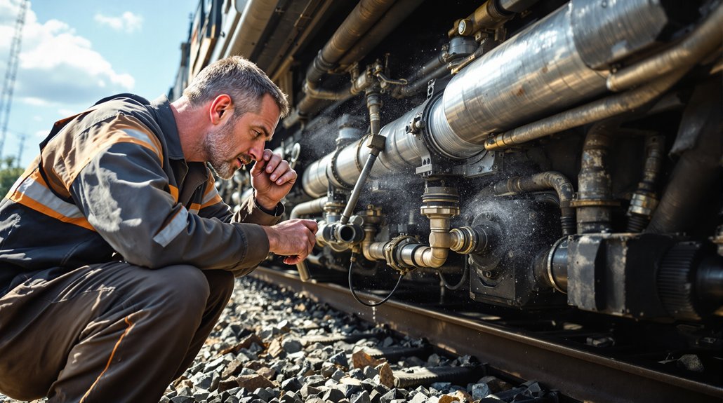
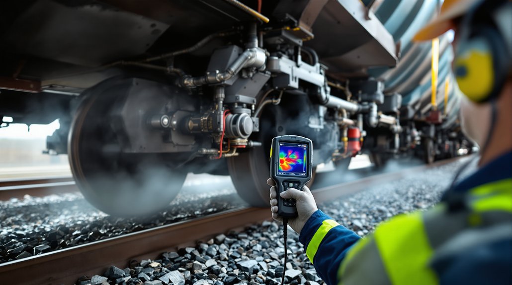
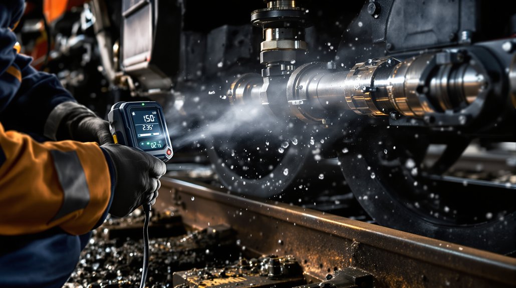
Regular inspection and maintenance are crucial for the longevity of WABCO air compressors in locomotive applications. Check the compressor regularly for any signs of leaks, unusual noises, or vibrations. Inspect the air lines, fittings, and connections for any damage or wear. Ensure the compressor is properly lubricated according to the manufacturer’s recommendations. Cleaning the area around the WABCO compressor head can help prevent debris from entering the system, ensuring that you will not have to replace any parts regularly. Mikura International recommends following a strict maintenance schedule to prevent unexpected failures and ensure the compressor operates at peak efficiency.
Signs of Wear and Tear to Look Out For
Be vigilant for signs of wear and tear on your WABCO air compressor. Reduced air output, frequent cycling, and unusual noises are indicators of potential issues. Check for oil leaks around the compressor, which could indicate a failing seal or gasket, like the head gasket. Overheating can also signal problems with the compressor’s internal components. Inspect the air filter regularly and replace it as needed. Contact Mikura International if you observe any of these signs, so that you can get the WABCO inform catalog handy to make sure you are up-to-date with the parts. Addressing these issues promptly can prevent more significant damage and costly repairs.
Best Practices to Extend the Life of Your Compressor
To extend the life of your WABCO air compressor, implement best practices. Some examples of these practices include:
- Maintaining proper lubrication levels and using high-quality lubricants.
- Ensuring the air intake filter is clean to prevent contaminants from entering the compressor.
Periodically inspect and replace worn components, like the 85mm head gasket, before they cause major failures. Protect the compressor from extreme temperatures and harsh weather conditions. Mikura International offers a wide range of original and new WABCO parts to help you maintain your compressor in top condition. Implementing these practices will help ensure the reliability and longevity of your WABCO twin cylinder air compressor.
Sourcing WABCO Parts Through Mikura International

Why Choose Mikura International for Your Spare Parts
When sourcing WABCO parts, Mikura International stands out due to our commitment to quality and reliability. We offer a comprehensive selection of original and new WABCO parts with material numbers, including the 85mm head gasket kit. Our parts are sourced directly from reputable manufacturers, ensuring they meet stringent quality standards. With years of experience in the locomotive and marine engine part industry, we understand your needs and provide expert support to help you find the right parts quickly. By providing high-quality WABCO catalog parts, Mikura International guarantees that your Wabco compressor functions optimally.
How to Place an Order for the Head Gasket Kit
Placing an order for the WABCO 85mm head gasket kit from Mikura International is simple and efficient. Visit our website or contact our sales team directly to inquire about availability and pricing. Provide the specific details of your WABCO air compressor model to ensure compatibility. Our team will guide you through the ordering process and provide a detailed quotation. We offer flexible payment options and efficient shipping to ensure you receive your parts promptly. Mikura International makes acquiring your needed Wabco compressor head as easy as possible.
Customer Support and After-Sales Services
Mikura International is committed to providing exceptional customer support and after-sales service. Our knowledgeable team is available to answer your questions, provide technical assistance, and assist with any issues you may encounter. We offer warranty support on our WABCO parts, ensuring your satisfaction. We also provide guidance on installation and maintenance best practices to help you maximize the lifespan of your WABCO air compressor. Our commitment to customer satisfaction makes Mikura International your trusted partner for all your locomotive parts needs. We will make sure you know everything, from wabco catalog parts to a gasket by wabco with material.