You must replace railway brake system diaphragms according to strict federal intervals that range from 368 days for conventional locomotives to 1,840 days for advanced air dryer-equipped systems under 49 CFR 238.309. DMU units allow 500-day cycles, while WABCO systems require 368-day replacements for compliance. Delayed maintenance triggers regulatory violations, equipment failures, and safety risks that can halt operations. Understanding these classification systems and their specific requirements will help you optimize maintenance schedules while ensuring full regulatory compliance.
Key Takeaways
- Standard diaphragm replacement intervals range from 368 to 1,840 days depending on locomotive type and air system configuration.
- Systems with air dryers enable extended maintenance cycles, with 26-C systems allowing 1,840-day diaphragm replacement intervals.
- Conventional locomotives without air dryers must follow 736-day replacement intervals established by federal regulatory guidelines.
- DMU air dryers with integrated filtration systems permit shorter 500-day replacement intervals due to enhanced system protection.
- Replacement schedules cannot be reduced without FRA approval and must include complete disassembly and thorough component inspection.
Regulatory Framework for Brake Equipment Maintenance Under 49 CFR 238.309

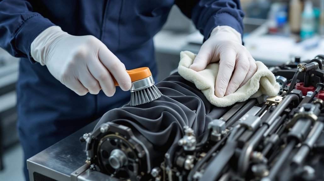
When maintaining brake equipment under 49 CFR 238.309, you must completely disassemble all pneumatically sealed components containing moving parts at prescribed intervals. This regulation mandates thorough cleaning, lubrication, and replacement of deteriorating parts across all brake system components, including air valves, reservoirs, and control units.
You’re required to conduct pneumatic sealing inspections at scheduled intervals regardless of operational history. Equipment becomes defective immediately upon discovering noncompliance with maintenance schedules. Deteriorated seals, lubrication failures, or component wear automatically trigger defect status, requiring resolution before returning to service.
You can’t reduce standard maintenance intervals without FRA approval. Alternative procedures require petitions demonstrating equivalent or superior safety levels per § 238.21 guidelines. Moving parts in pneumatic sealing systems need synchromatic inspection to maintain air-tight integrity. Maintenance inspections must prevent corrosion in precision-sealed units, with replacement intervals aligned to material degradation rates for continuous brake system reliability. Filtering devices or dirt collectors must be cleaned, repaired, or replaced as part of the mandatory maintenance process.
Maintenance Interval Classifications by Locomotive Type and Air System Configuration

When you’re maintaining DMU air dryers, you’ll benefit from extended replacement intervals due to their integrated filtration systems that reduce contamination-related diaphragm degradation. Conventional locomotives require more aggressive scheduling because they lack these protective mechanisms and operate under higher cyclic stress loads. You must adjust your maintenance protocols accordingly, as DMUs typically allow 500-day intervals while conventional units demand the standard 368-day WABCO replacement cycle to maintain regulatory compliance. Systems without air dryers follow the 736-day intervals established by federal maintenance guidelines for enhanced operational efficiency.
DMU Air Dryer Benefits
Five distinct maintenance classification systems govern DMU air dryer operations, each designed to maximize equipment reliability while extending service intervals beyond standard pneumatic configurations. You’ll benefit from air dryer efficiency that enables 1,472-day level two maintenance cycles for semi-permanently coupled locomotives, compared to standard 368-day intervals. Your moisture control systems automatically drain condensation, reducing filter replacement frequency and preventing corrosion-related failures.
These extended intervals directly reduce operational costs while maintaining regulatory compliance under §229.29. You’ll achieve power efficiency through dry compressed air that minimizes brake system freezing and contamination risks. Alaska Railroad’s adoption of longer overhaul cycles demonstrates proven reliability. Your air dryer systems complement CCB configurations, providing redundancy that prolongs service between major overhauls while ensuring consistent performance in high-humidity environments. All maintenance activities require detailed records that include locomotive number, inspection dates, and technician signatures for regulatory compliance.
Conventional Locomotive Requirements
Conventional locomotives operate under significantly different maintenance protocols than DMU systems, requiring shorter replacement intervals and more frequent inspections due to higher operational stress and regulatory oversight. You’ll need to follow EMD’s 92–184 day inspection cycles while maintaining CFR Part 229 compliance. Diaphragm materials face accelerated degradation from chemical exposure and cyclic stress, particularly in high-usage applications where air systems exceed 30 psi static thresholds.
| System Type | Replacement Interval |
|---|---|
| EMD Pneumatic Control | 92-184 days |
| Wabco Brake Diaphragms | Preemptive replacement |
| WAP/WAG Brake Blocks | Wear limit based |
| Air Test Connections | Minor maintenance cycle |
| Digital Control Systems | Extended with analytics |
Your maintenance strategies must prioritize brake subsystems and valve mounting integrity to prevent failures that compromise operational safety. Performance indicators should guide repair timelines to ensure safety protocols dictate how urgent issues are addressed across all locomotive systems.
Extended Service Intervals for Advanced Brake Systems With Air Dryers

Although most railway brake systems require frequent maintenance intervals, advanced brake systems equipped with air dryers can extend your service schedules greatly beyond standard regulatory minimums. Air dryer effectiveness enables these sophisticated configurations to operate safely with dramatically reduced maintenance frequencies, transforming traditional maintenance paradigms.
Brake system innovations have revolutionized compliance intervals through three critical maintenance tiers:
- 26-L brake systems – You’ll achieve 1,104-day intervals with proper air dryer integration, reducing downtime costs greatly
- Dedicated coupled units – Your 26-L systems with air dryers qualify for 1,472-day extensions, maximizing operational efficiency
- Advanced architectures – CCB-1, CCB-2, KB-HS1, and Fastbrake systems allow 1,840-day intervals when you maintain 100% air dryer adoption
You must verify compatible engineer brake valves like PS-68, 26-C, or RT-2 configurations. These extended intervals require strict documentation on Form F6180-49A, but they’ll considerably reduce your maintenance burden while maintaining regulatory compliance. Main reservoirs must undergo hydrostatic pressure tests at intervals not exceeding 736 days to ensure continued operational safety.
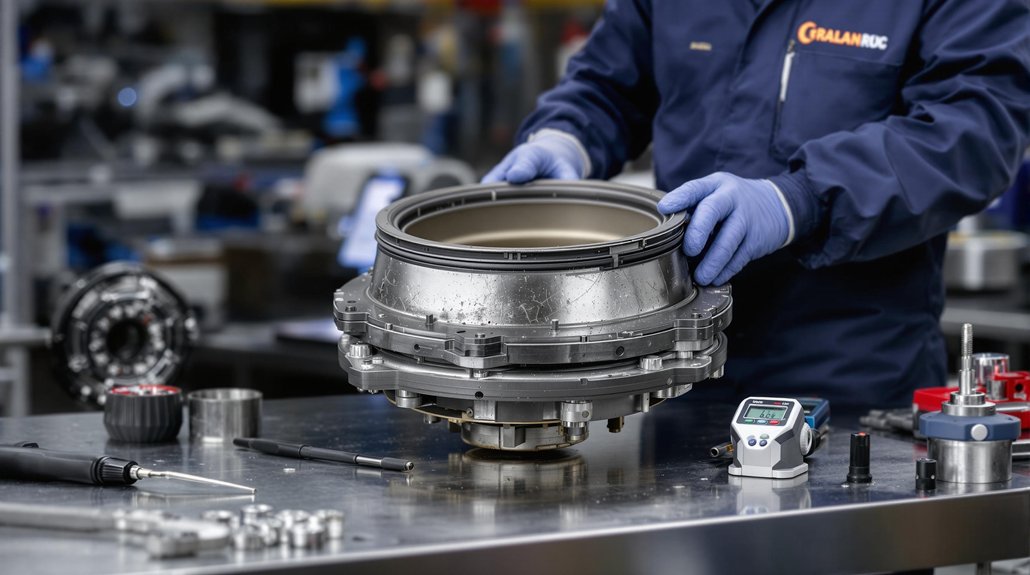
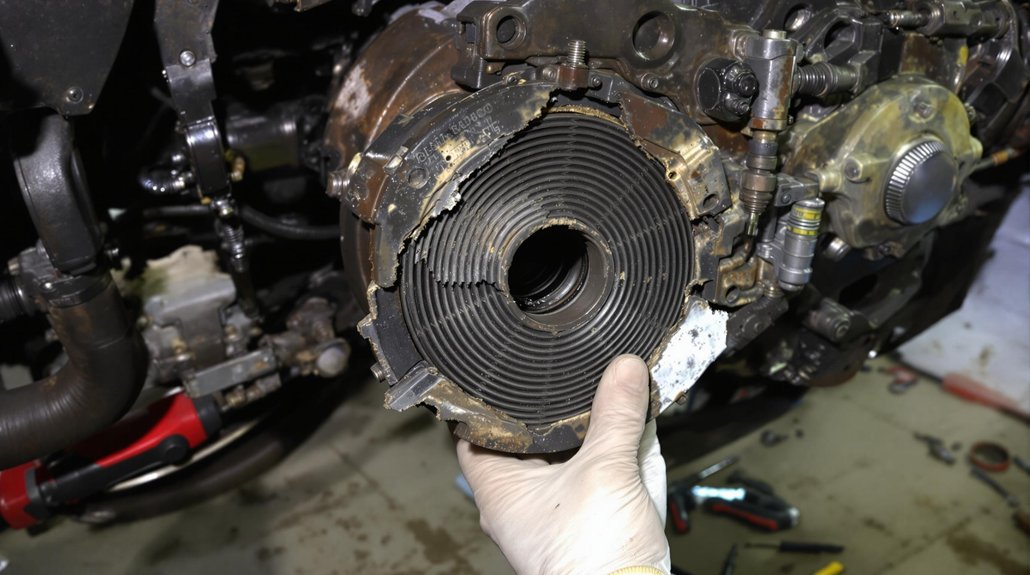
Component Replacement Criteria and Deterioration Assessment Standards

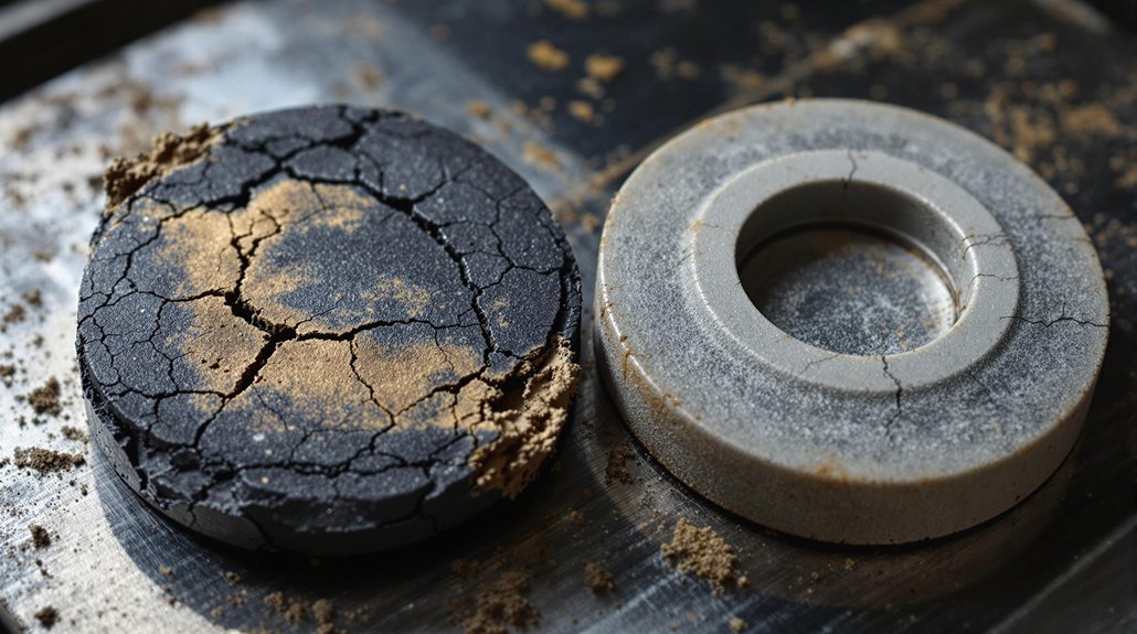
Component replacement scheduling demands rigorous assessment protocols that go beyond simple time-based intervals. You’ll need to establish clear deterioration indicators through systematic evaluation methods that include visual inspection for cracks, fraying, or surface wear, thermal imaging to detect heat-related degradation, and ultrasonic testing for internal material integrity assessment.
Your replacement guidelines must incorporate hardness profiling to measure material composition changes and thorough service lifespan tracking through historical maintenance records. You can’t rely solely on manufacturer schedules—condition-based maintenance prioritizes inspection frequency based on actual usage patterns and operational stress.
Pre-service inspections are mandatory before revenue service, while post-accident evaluations require immediate assessment following collision events. You must align scheduled maintenance intervals with manufacturer-recommended cycles but adapt them based on specific operational conditions. Railway diaphragms require fail-safe design principles to prevent unsafe conditions during system malfunctions. Regulatory oversight through unannounced safety checks guarantees compliance with established deterioration assessment standards.
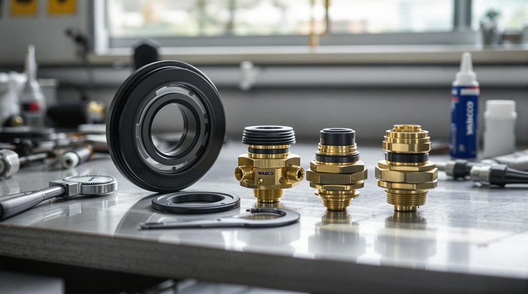
Impact of PS-68, 26-C, and ABDW Control Valve Systems on Maintenance Schedules

When implementing maintenance schedules for railway brake control systems, you’ll find that PS-68, 26-C, and ABDW valve configurations create distinctly different interval requirements that directly impact diaphragm replacement timing.
PS-68 valves present significant maintenance challenges with their 736-day intervals and heightened susceptibility to air contamination. You’ll need more frequent reactive maintenance due to early diaphragm deterioration, often requiring alignment with 31- or 92-service-day inspections to prevent subsystem failures.
26-C systems offer enhanced diaphragm longevity, extending replacement cycles to 1,840 days when equipped with KB–HL1/HS1 air dryers. This configuration reduces component wear substantially.
ABDW valves demand predictive diagnostics for efficient scheduling:
- Biennial pressure monitoring prevents catastrophic failures
- Service day-based maintenance maximizes replacement costs
- Quarterly diagnostic checks guarantee regulatory compliance under §229.27
You’ll achieve compliance by documenting air dryer integration status and maintaining audit-ready FRA Form records.
Level One Maintenance Requirements and 368-Day Critical Component Inspections

Five critical safety protocols govern Level One maintenance requirements, establishing mandatory 368-day inspection cycles that directly impact railway operational safety and regulatory compliance. You’ll conduct visual inspections examining diaphragm surfaces for perishment, fiber cracking, or structural thinning that compromises operational integrity. Your inspection frequency must align with 49 CFR §238.503 requirements, ensuring diaphragm performance meets federal standards for braking systems and pneumatic operations.
You’re required to perform pressure and leak testing validating diaphragm integrity against operational loads and unexpected pressure spikes during service. Critical components with safety risks—including braking diaphragms and pressurized pneumatic systems—demand immediate replacement when structural defects appear. You’ll document inspection results, component history, and renewal dates in maintenance logs for audit readiness. Training protocols require technician certification for specialized diaphragm testing using manufacturer guidelines integrated with railroad safety standards, ensuring qualified personnel handle safety-critical components during 368-day inspection cycles. Additionally, annual program reviews must be conducted to verify maintenance procedures comply with evolving federal safety standards and operational requirements.
Safety Testing Protocols and Pre-Departure Brake System Verification

You must complete thorough pre-departure brake checks before every terminal departure to guarantee diaphragm integrity and system compliance with Class I brake test requirements under §232.205. Your emergency application inspections verify that brake pipe communication remains uncompromised and that diaphragms can withstand the pressure differentials created during irreversible emergency stops. These mandatory verification protocols protect against catastrophic brake failures that could result from deteriorated diaphragm components compromising your train’s braking capacity. Train operations cannot commence with less than 85% operative brakes across all cars in the consist.
Pre-Departure Brake Checks
Before each train’s departure, you must conduct thorough brake testing protocols that form the cornerstone of railway safety compliance. Your pre departure procedures under 49 CFR part 215 require designated inspector oversight and extensive system verification. You’ll perform Class I brake tests ensuring brake pipe leakage remains ≤5 psi/min and air flow stays ≤60 CFM.
Critical brake inspection techniques include:
- System charging verification – achieving ≤15 psi differential from locomotive regulating valve settings
- 20 psi reduction testing – confirming every car’s brake response and 3-minute application retention
- Release confirmation checks – visual verification at ≤10 mph speeds ensuring complete brake disengagement
You must validate brake assignment through physical inspection or ETD monitoring, requiring ≥5 psi pressure differentials. Rear-of-train pressure compliance demands ≥75 psi minimum with ≤15 psi variance from locomotive settings. For freight trains operating in ECP brake mode, a qualified mechanical inspector must conduct the Class I brake test in accordance with § 232.205(c) compliance requirements.
Emergency Application Inspections
When emergency conditions arise, your inspection protocols must shift from routine verification to thorough safety validation under Activity 217E compliance requirements. Emergency inspections demand immediate prioritization of any defects discovered during diaphragm system assessments. You must conduct cross-functional verification of brake systems, including coupling alignment checks before equipment movement. Post-incident inspections become mandatory for brake components that fail during emergency applications.
Your compliance narratives must detail specific findings regarding diaphragm integrity under emergency conditions. Document safety appliance status, including tension handles and latching mechanisms that affect brake system performance. Coordinate with signal teams during joint inspections to guarantee interoperability between brake and signal systems. Upload inspection data weekly to FRA systems, with immediate corrections issued for any compliance violations discovered during emergency application testing. Emergency brake testing must include Class Three protocols for comprehensive system validation.
Industry Compliance Standards and Documentation Requirements for Railway Operators

Railway operators must navigate multiple regulatory frameworks that establish mandatory compliance standards for safety equipment maintenance and documentation. You’ll need to adhere to APTA rail standards, CSX proximity restrictions, and FMCSA regulations while maintaining thorough records for compliance audits.
Your documentation strategies must include hours-of-service logs with seven-day histories, medical examiner certifications, and safety incident tracking with strict reporting timelines. You’re required to maintain equipment release documentation and conduct annual MVR audits to guarantee operational eligibility.
Critical compliance failures that put lives at risk:
- Missing pre-movement inspections of couplers, lineups, and obstructions before equipment operation
- Inadequate flag person monitoring within 25 feet of main tracks during railcar movements
- Incomplete ELD system submissions to DOT compliance teams beyond the 24-hour deadline
You must implement three-step protection protocols, maintain wheel chock documentation, and guarantee all safety equipment inspections align with manufacturer intervals to avoid regulatory violations and operational shutdowns.
Frequently Asked Questions
Can Weather Conditions Affect Diaphragm Replacement Timing Beyond Standard Intervals?
Weather brutally assaults your diaphragms with relentless thermal cycling, moisture infiltration, and freeze-thaw destruction that’ll shred standard replacement schedules. You must accelerate maintenance intervals when experiencing extreme temperature swings, prolonged humidity exposure, or harsh winter conditions. Weather impact demands proactive seasonal maintenance adjustments – reducing intervals by 25-40% during severe conditions guarantees regulatory compliance and prevents catastrophic failures in safety-critical applications.
What Are the Cost Differences Between OEM and Aftermarket Diaphragms?
You’ll face significant cost differences between OEM and aftermarket diaphragms that extend beyond initial pricing. While aftermarket options appear cheaper upfront, OEM advantages include superior materials, regulatory compliance, and extended warranties that reduce long-term expenses. Aftermarket disadvantages encompass frequent replacements, potential AAR violations, voided warranties, and liability risks. You’re accepting substantial financial exposure when choosing non-OEM parts despite apparent savings.
How Do Altitude Changes Impact Diaphragm Performance and Replacement Schedules?
You’ll experience significant altitude effects on diaphragm performance due to pressure differentials and temperature extremes. Diaphragm materials deteriorate faster at high elevations from UV exposure, thermal cycling, and reduced air density affecting pressure regulation. You must shorten replacement intervals from standard 92-day schedules, implement frequent pressure testing, and specify altitude-resistant elastomers. You’ll need enhanced inspection protocols for cracking and recalibrate governors regularly to maintain regulatory compliance and prevent critical system failures.
Are There Visual Inspection Techniques to Identify Early Diaphragm Wear?
Like a detective examining evidence, you’ll spot early wear through systematic visual inspection before catastrophic failure occurs. You must check for hairline cracks, surface discoloration, and material degradation around stress points. Look for uneven thickness, frayed edges, or loss of elasticity when flexed. Document any bulging, pitting, or surface oxidation immediately. These early wear indicators demand immediate attention to prevent brake system compromise and regulatory violations.
Can Diaphragms From Different Manufacturers Be Mixed Within Same Brake System?
You shouldn’t mix diaphragms from different manufacturers within the same brake system due to critical diaphragm compatibility issues. Each manufacturer’s specifications differ in dimensions, materials, and pressure responses, creating dangerous mismatches. AAR standards require uniform components to prevent air leakage, pressure inconsistencies, and potential brake failures. Cross-manufacturer mixing violates FRA regulations, voids warranties, and increases derailment risks. Always use manufacturer specifications-compliant parts for regulatory compliance and system safety.