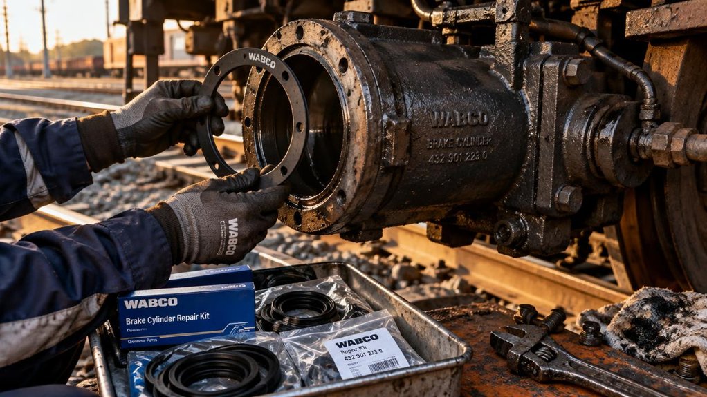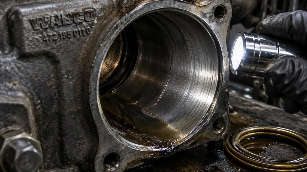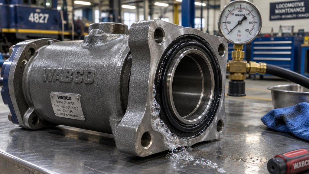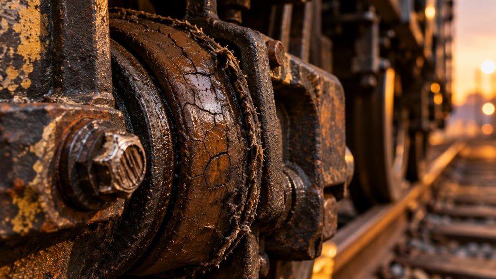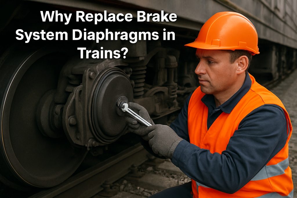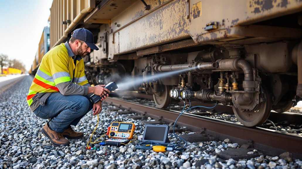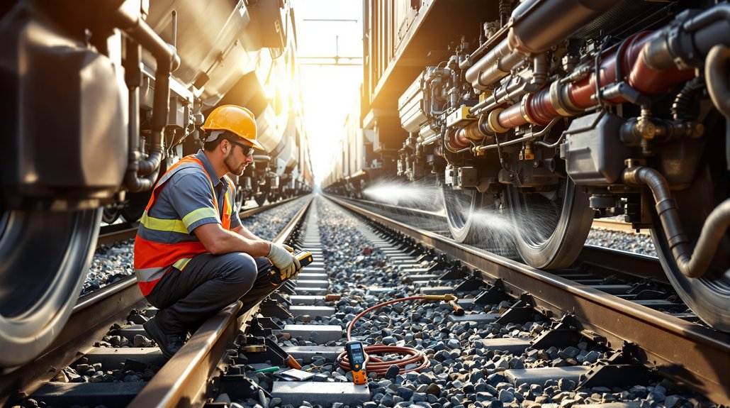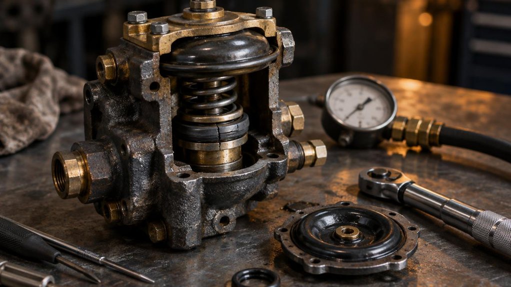
Why Replace Brake System Diaphragms in Trains?

Why Replace Brake System Diaphragms in Trains?

Locomotive brake reliability underpins safety and on-time operations. Diaphragm condition directly affects braking force, modulation, and overall train control. Degraded diaphragms can extend stopping distances and elevate risk during critical maneuvers in Australian rail networks.

Context and relevance for heavy-duty locomotive brake systems

Diaphragms regulate braking pressure in locomotive service. Worn or damaged diaphragms distort force distribution, reducing control. Timely replacement maintains braking consistency and minimizes downtime.

  • Consistent braking torque enhances safety under heavy loads.
  • Predictable response helps prevent wheel slip during adhesion loss.
  • Fewer in-service failures reduce maintenance headcount and costs.
  • Standardized parts simplify sourcing for spares managers.
  • ISO-certified supply chains ensure traceability and quality.

Mikura International’s role in diaphragm replacement components

At Mikura International, we provide reliable diaphragm replacements tailored for locomotive braking systems, prioritising rapid response, sourcing integrity, and on-time delivery to support critical maintenance windows.

  • Dedicated focus on heavy-duty diaphragm components for WABCO-based systems.
  • Ethical sourcing with traceability from ISO-certified processes.
  • Global service reach with local speed for Australia-based spare parts teams.

1. Safety-Driven Failure Modes of Brake Diaphragms

Common diaphragm wear and rupture scenarios

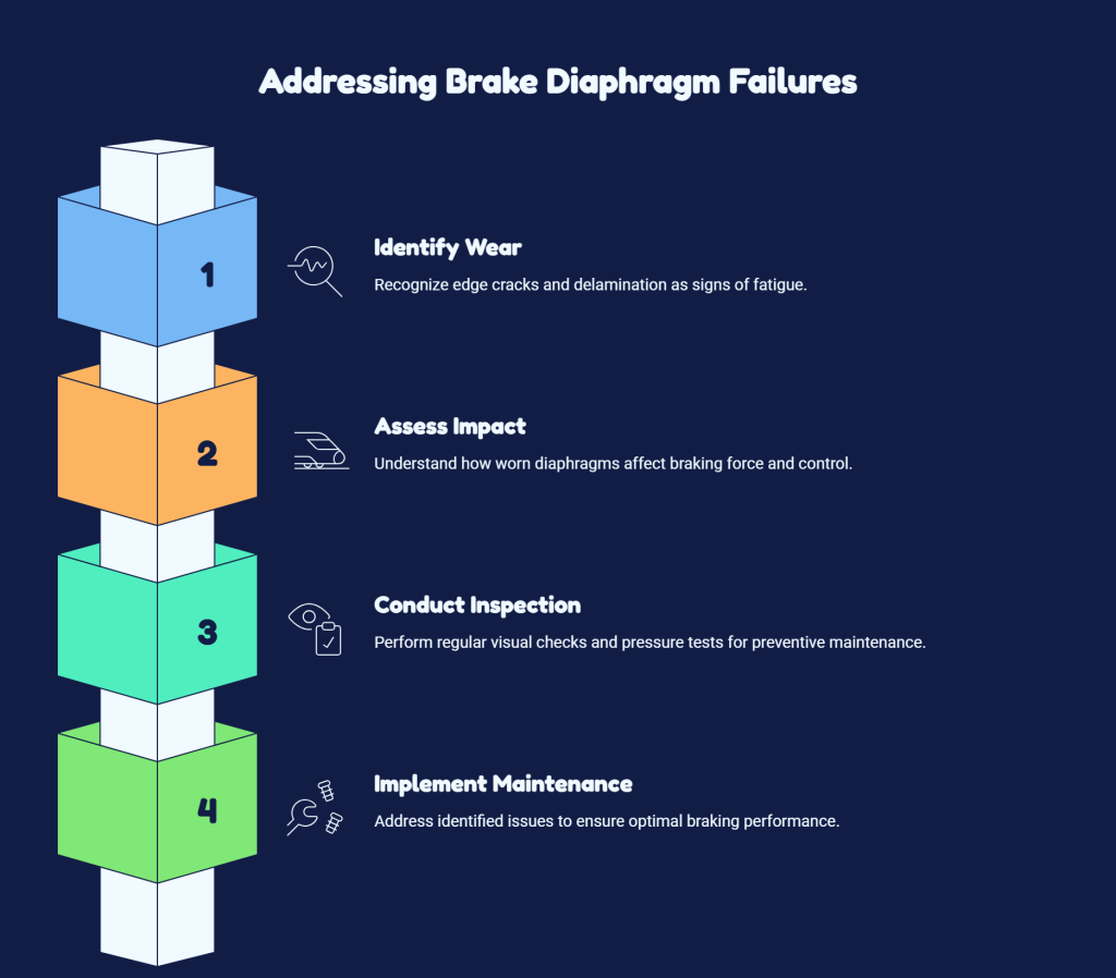
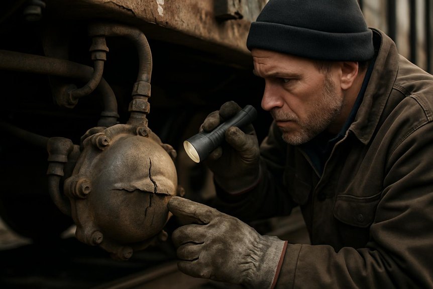
Diaphragms degrade from cyclic pressure loading and exposure to environmental contaminants. Edge cracking and delamination are typical signals that the seal surface is compromised. Sudden ruptures tend to occur under peak braking demands in older installations where fatigue has accumulated.

Safety-Driven Failure Modes of Brake Diaphragms
  • Edge cracks indicate fatigue and require timely inspection.
  • Delamination reduces effective contact area for sealing.
  • Grooving from debris or misalignment accelerates wear progression.

Impact on braking force and train control

Worn diaphragms reduce braking torque and impair modulation. This can cause uneven pad loading and increase wheel slip risk. Inconsistent brake application challenges crew control during critical decelerations.

Inspection indicators and preventive signs

Key cues include uneven pressure readings and audible hiss during tests. Regular visual checks for fissures, hard spots, and deformation support proactive maintenance planning.

  • Pressure uniformity across channels
  • Visible cracks or bulges upon inspection
  • Changes in braking response times during tests

2. Performance Benefits of New Diaphragms

Restored braking efficiency and consistency

New diaphragms restore nominal contact pressure and uniform force transmission across brake circuits, yielding predictable wheel deceleration under heavy haul conditions.

  • Uniform seal contact reduces lag during high load stops.
  • Consistent pedal feel supports driver confidence in critical maneuvers.
  • Eliminates uneven wear patterns that can degrade long term performance.

Improved response times and modulation

Fresh diaphragms respond promptly to pressure changes, enabling finer control of braking force. This improves adhesion management on varying track conditions and reduces abrupt deceleration.

  • Faster pressure build and release enhances traction control.
  • Smoother modulation supports seamless coast-to-stop transitions.
  • Better repeatability across multiple braking cycles.

Reduced risk of brake system imbalance

Replacing diaphragms with new parts minimizes asymmetry between brake channels, promoting balanced pressure distribution during rapid operational changes.

  • Lower incidences of uneven braking across bogies.
  • Decreased need for corrective adjustments during service.
  • Enhanced safety margins in horizon-limited braking scenarios.
AttributeOld DiaphragmNew Diaphragm
Braking efficiencyVariableConsistent
Response timeSlowerFaster
System balanceProne to imbalanceBalanced

3. Economic Rationale for Replacement

Cost of failures vs. cost of preventative replacement

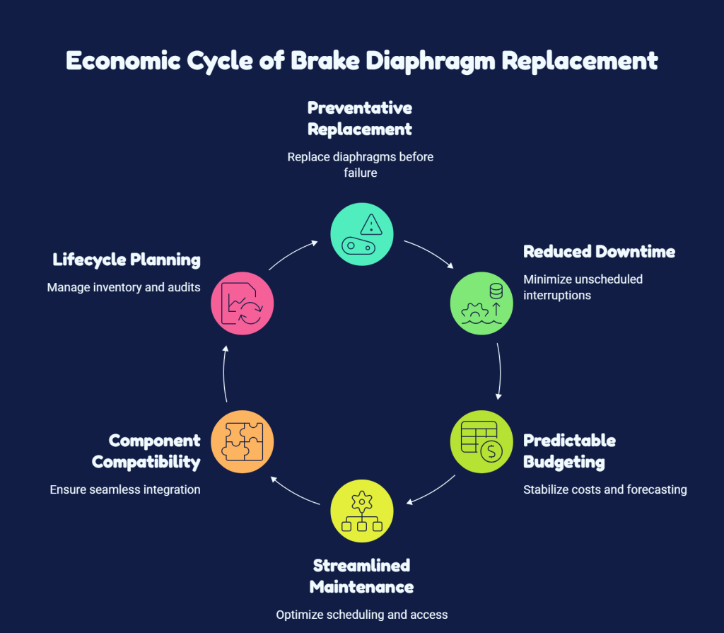
Preventative replacement reduces the likelihood of on track failures and unscheduled downtime. Worn diaphragms can trigger sudden braking issues that necessitate emergency actions, making budgeting for spares and maintenance more predictable.

Economic Rationale for Replacement
  • Save on unplanned detours and penalties
  • Avoid rush orders for emergency diaphragm replacements
  • Stabilize procurement cycles for budget forecasting

Downtime reduction and maintenance scheduling

New diaphragms streamline maintenance planning and shorten brake system access time. Regular intervals improve fleet readiness for peak operations.

  • Shorter service windows during planned downtimes
  • Improved on-time performance for yard and port tasks
  • Better alignment with track access and crew rosters

Component compatibility and lifecycle considerations

Modern diaphragms are designed for long lifecycles across legacy and current fleets, lowering compatibility risk and part count variability. Lifecycle planning supports steady spares inventories and auditability.

  • Standard interfaces simplify stocking
  • Improved forecast accuracy for wear-out cycles
  • Clear provenance supports audits and compliance
Economic FactorPreventative ReplacementReactive Replacement
Downtime impactLow to moderateHigh
Spare part cost predictabilityHigh predictabilityLow predictability
Maintenance scheduling easeFront-loaded planningLast-minute adjustments

4. Material Technologies in Modern Diaphragms

Elastomeric vs. composite diaphragm materials

Elastomeric diaphragms employ rubber-like polymers to provide flexible sealing surfaces, while composite diaphragms combine fibers with resin matrices to achieve greater stiffness and more uniform load distribution under high pressure.

  • Elastomeric: strong sealing capability with favorable cost profile.
  • Composite: higher stiffness, improved heat management.
  • Selection should align with expected brake circuit pressures and operating temperatures.

Wear resistance and temperature tolerance

Diaphragms are designed to withstand abrasive dust, exposure to oil mist, and sustained high-load cycles. Temperature tolerance helps prevent softening or creep during extended duty cycles.

  • Wear life improves with optimized material formulation.
  • Performance remains stable across elevated temperatures.
  • Additives enhance resilience against micro-ruptures and environmental factors.

Compatibility with EMD, GE, and ALCO braking systems

Material selection targets reliable interfacing with both legacy and modern actuators, preserving deformation patterns that maintain cross-brand balance.

  • Standardized mounting interfaces simplify stocking and maintenance.
  • Material specs align with cross-brand pressure tolerances.
  • Traceability supports after-sales service and audits.
AspectElastomericComposite
Sealing performanceStrongModerate to strong
Temperature rangeLowerHigher
Wear lifeGoodExcellent

5. Installation Best Practices for Train Brakes

Pre-installation inspection and tooling

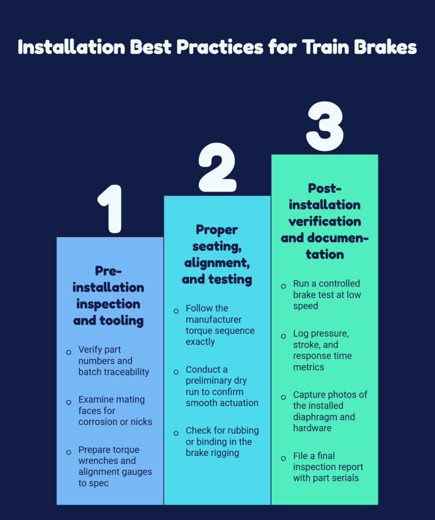
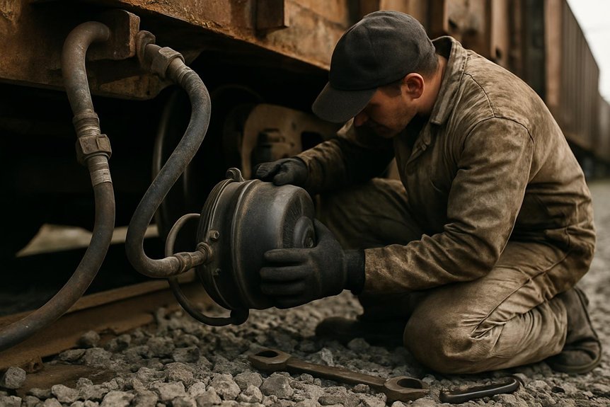
Perform a targeted pre-installation review of the diaphragm housing and mating surfaces for signs of wear or damage. Confirm tool calibration and compatibility with the specific WABCO kit in use.

Installation Best Practices for Train Brakes
  • Verify part numbers and batch traceability
  • Examine mating faces for corrosion or nicks
  • Prepare torque wrenches and alignment gauges to spec

Proper seating, alignment, and testing procedures

Seat the diaphragm to full contact without introducing misalignment. Align to the actuator shaft and verify seating with light pressure before full compression.

  • Follow the manufacturer torque sequence exactly
  • Conduct a preliminary dry run to confirm smooth actuation
  • Check for rubbing or binding in the brake rigging

Post-installation verification and documentation

Verify functional performance and log results for traceability. Capture critical metrics and imagery for records.

  • Run a controlled brake test at low speed
  • Log pressure, stroke, and response time metrics
  • Capture photos of the installed diaphragm and hardware
  • File a final inspection report with part serials

6. Diagnostics and Testing After Replacement

Pressure and leakage tests

Perform post-installation pressure hold tests to verify seal integrity and sustained pressure. Record stabilization time and readings to support traceability.

  • Isolate the circuit and apply nominal operating pressure
  • Monitor for any pressure drift or transient fluctuations
  • Inspect seals and joints for signs of leakage under load

Brake rigging and canalization checks

Verify that brake rigging operates smoothly after diaphragm seating and that canalization routes remain unobstructed within tolerances.

  • Assess linkage clearances and pivot points
  • Validate sensor signals for proper canal flow
  • Confirm freedom from rubbing or binding across the full stroke

Performance run and safety certifications

Execute a controlled performance run to confirm brake force profiles align with baseline data. Ensure compliance with all safety standards and complete certification documentation.

Test AreaKey MetricAcceptance
Pressure stabilitySteady within 2%Pass
Actuation timingWithin planned windowPass
Leakage checkNo detectable leaksPass

7. Supplier Considerations: Choosing Mikura International Diaphragms

Quality assurance and traceability

Quality starts at the source. Each diaphragm batch undergoes rigorous testing to meet industry standards. We maintain full traceability from material receipt to final delivery.

Choosing Mikura International Diaphragms
  • Certified material lots with tamper-evident records
  • Lot-based inspection reports available on request
  • Non-conformance tracking and corrective actions documented

Cost-effective sourcing and lead times

Smart procurement supports predictable maintenance budgeting. Mikura International aligns pricing with demand cycles and maintains stock for critical routes.

  • Competitive unit pricing for bulk orders
  • Flexible incoterms to suit Australian operations
  • Dedicated safety stock to minimize downtime

Support, warranties, and global service reach

Local support complements our global coverage. Comprehensive warranties simplify lifecycle management and after-sales service.

  • On-site technical support in major Australian ports
  • Warranty terms aligned with diaphragm lifecycle expectations
  • Access to a global service network for rapid replacements
ConsiderationMikura International Advantage
Quality controlEnd-to-end QA with traceable batches
Lead timesOptimized stock levels and fast dispatch
SupportLocal and global service team with clear warranties

FAQ

What is the primary purpose of replacing WABCO locomotive diaphragms?

The diaphragm acts on brake chamber actuation and pressure transfer. Replacing worn diaphragms maintains predictable braking forces and reduces the likelihood of uneven brake application.

When should diaphragms be replaced?

Replace at signs of wear, cracking, or deformation. Schedule during planned maintenance to minimize downtime.

What inspection indicators signal imminent replacement?

  • Visible cracks or blistering on the diaphragm surface
  • Uneven seating or reduced actuation sensitivity
  • Excessive wear at attachment points
  • Pressure drift or leakage in the brake circuit

How does replacement affect braking performance?

New diaphragms restore consistent stroke, improve response, and reduce brake imbalance during rapid deceleration.

What installation checks ensure a reliable fit?

  • Pre-installation inspection of seating surfaces
  • Correct diaphragm alignment with the chamber
  • Post-installation pressure hold tests and a controlled brake run

How should diaphragms be sourced for Australian operations?

Source from a supplier with documented QA, traceability, and regional support like Mikura International. Confirm compatibility with EMD, GE, and ALCO systems.

Can I combine diaphragm replacement with other brake maintenance?

Yes. Align diaphragm replacement with routine brake rigging checks and canalization inspections to optimize downtime and document all actions.

QuestionAnswer
Primary purposeEnsure proper actuation and pressure transfer
Replacement signalsWear, cracks, deformation, leakage
Performance impactRestored consistency and response

Conclusion

Replacing brake system diaphragms on locomotives ensures predictable braking behavior and reduces variability in performance across operating conditions. This supports safer train operations and helps align maintenance with planned schedules.

Key takeaways to guide your next steps:

  • Plan diaphragm replacement during scheduled maintenance to minimize unscheduled downtime.
  • Prioritise diaphragms with proven wear resistance and high temperature tolerance for harsh rail environments.
  • Verify compatibility with EMD, GE, and ALCO brake systems to prevent seating or actuation issues.
  • Maintain complete inspection records for traceability and audits.
  • Leverage local Australian support for on-site verification and rapid replacements.
AspectImpact
SafetyReduces misapplication risk and improves control accuracy
ReliabilityRestores stroke consistency and response timing
MaintenanceProvides predictable lead times for planning

For ready access to certified diaphragms and expert guidance, Mikura International supports Australian operations with traceable quality and dependable delivery.

Fix Freight Train Brake Diaphragm Problems

Fix Freight Train Brake Diaphragm Problems

Freight train brake diaphragm failures often cause air loss, weak braking, and unexpected delays. Crews need fast, safe ways to confirm leakage before it affects train movement. A structured inspection helps locate the problem, protect personnel, and reduce repeat failures in locomotive and freight brake systems.

  • Listen for hissing near brake chambers and related pneumatic fittings.
  • Watch for frequent compressor cycling during charging.
  • Check reservoir pressure stability after charging the system.
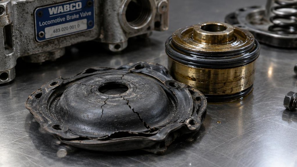
  • Inspect diaphragm areas for cracks, hardening, or deformation.
  • Confirm brake pipe leakage through approved test procedures.
  • Use calibrated gauges for all pressure checks.
  • Isolate the pneumatic circuit before any repair work.
  • Apply lockout tagout before opening any brake component.
  • Replace worn diaphragms with genuine locomotive brake parts.
Common SymptomLikely CauseCorrective Action
Hissing near brake chamberDamaged brake diaphragmIsolate, depressurize, and replace the diaphragm
Frequent compressor cyclingAir leakage in brake circuitPerform leakage test and inspect sealing points
Unstable reservoir pressureInternal or external air lossCheck valves, fittings, and diaphragm condition
Weak brake responseDiaphragm not holding pressureReplace with correct genuine locomotive part
Repeat cold-weather leakageHardened or shrunken sealsInspect seals and use approved replacement parts

You fix freight train brake diaphragm problems by spotting air loss early. Then, confirm the issue with required leakage tests.

Listen for hissing at brake chambers. Watch compressor cycling during system charging. Check if reservoir pressure remains stable after charging.

Charge the brake system as specified. Make the required brake reduction.

Then verify that leakage remains within approved limits. Follow applicable AAR and FRA inspection requirements for freight train brake systems.

Before repair, isolate the pneumatic circuit. Apply lockout tagout procedures.

Confirm zero pressure with a calibrated gauge before opening any component. Never remove brake parts while pressure remains in the system.

Inspect the brake diaphragm for cracking, stiffness, tearing, or deformation. Also check adjoining seals, fittings, and brake chamber surfaces.

Replace defective parts with genuine locomotive brake components.

Cold weather can worsen diaphragm and seal problems. Low temperatures may harden rubber parts and reduce sealing performance.

Include cold-weather seal checks during scheduled brake inspections.

Mikura International supplies and exports genuine locomotive and marine engine parts. We supply parts from trusted brands such as ALCO, EMD, GE, and WABCO.

We are not the manufacturer. We support locomotive brake maintenance with genuine replacement parts for reliable service.

Key Takeaways

  • Identify diaphragm failure by hissing, excessive compressor cycling, unstable reservoir pressure, brake warnings, or corrosion around brake chambers.
  • Confirm leakage by charging the system, making a 20-psi service reduction, and checking loss against the 5-psi-per-minute limit.
  • Isolate the affected pneumatic circuit, apply lockout tagout, and verify zero pressure before loosening fittings or removing actuator parts.
  • Replace damaged diaphragms, seals, gaskets, and restricted hoses; mark line positions and preserve linkage alignment during disassembly.
  • Prevent repeat failures with dry compressed air, winter-rated seals, scheduled leak checks, and required AAR/FRA brake testing.

Spot WABCO Brake Diaphragm Failure Signs

hissing brake diaphragm leakage

How can you spot a failing WABCO brake diaphragm before it compromises locomotive stopping force? Start with symptoms during service brake application. Listen for hissing near brake chambers or exhaust ports when brakes are applied. Verify audible air paths safely, without disassembling test fittings.

During service braking, hissing near chambers or exhaust ports can signal diaphragm leakage before stopping force drops.

Note whether the compressor cycles excessively during braking. Check if reservoir pressure fails to stabilize through the brake cycle. These signs may indicate diaphragm leakage or related air loss.

Inspect brake chamber corrosion around clamps, pushrod openings, and mounting faces. Rust distortion can increase seal stress and accelerate diaphragm failure. Watch cab brake warnings, pressure imbalance codes, and pneumatic system alerts. Multiple warnings may suggest cascading air-loss conditions.

During depot checks, confirm slack adjustment basics. This helps ensure delayed engagement is not caused by excessive stroke. Treat sluggish brake response, weak emergency braking, or delayed deceleration as diaphragm risk. This is especially important after high-heat duty or heavy braking.

Review hose routing near brake chambers for abrasion and wear. Damaged hoses can mask chamber-related symptoms. Grinding or creaking during application requires immediate attention. Isolate the affected axle and schedule brake chamber inspection promptly.

Confirm Diaphragm Failure With Leakage Tests

brake pipe diaphragm leak test

Before condemning a WABCO brake diaphragm, confirm leakage through controlled locomotive brake pipe leakage testing.

Charge the air brake system to operational pressure. Confirm rear pressure is within 15 psi of that value. It must not be below 75 psi.

Position angle cocks and cutout cocks correctly. Inspect hoses for kinks, binding, fouling, or restrictions.

Make a 20-psi brake pipe service reduction. Wait 45 to 60 seconds, then lap the brake valve.

Verify cutout before timing leakage. Include the pressure-maintaining feature in this verification.

Read the locomotive brake pipe gauge. Confirm rear-end drop with a hand gauge or end-of-train device.

Leakage must not exceed 5 psi per minute during a Class I test.

Use airflow as an alternate method on qualified 26-L or equivalent locomotives. Keep flow at or below 60 cubic feet per minute. With distributed power or an air repeater controlling air from two or more locations, combined flow must not exceed 90 cubic feet per minute.

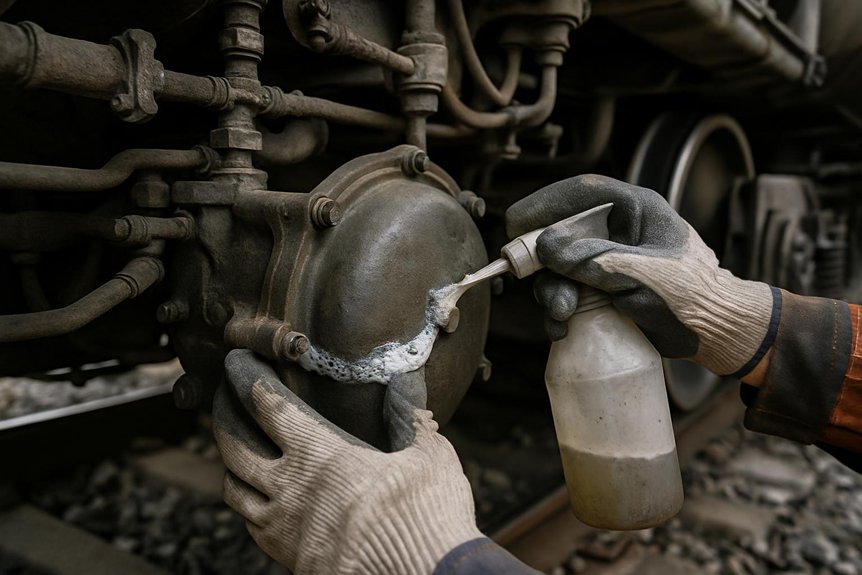
Document the test method clearly. Use soap suds or approved leakage apparatus to isolate the diaphragm leak.

Address Brake Diaphragm Pressure Loss Safely

isolate verify zero pressure

At the earliest indication of locomotive brake diaphragm pressure loss, isolate the affected pneumatic circuit. Treat the system as energized until proven safe.

Use approved procedures to close supply paths, vent trapped air, and prevent unintended recharge. Apply lockout tagout before loosening fittings, removing covers, or touching actuator hardware.

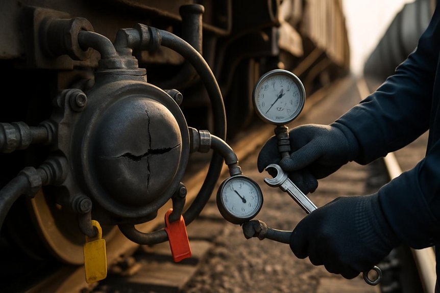
Confirm zero pressure with a calibrated gauge. Record the reading in the required maintenance documentation. Do not proceed until written verification confirms complete discharge.

Verify zero pressure using calibrated equipment, document the reading, and wait for written discharge confirmation before continuing.

Check leakage limits as specified for locomotive brake systems. Main reservoir loss must average no more than 3 psi per minute. This applies during a three-minute test after a 40% pressure reduction.

Brake pipe leakage must stay at or below 5 psi per minute. Test after a 10 psi reduction from at least 70 psi. In a 2019 loaded grain train occurrence, inadequate sustained braking in extreme cold preceded a runaway derailment.

Mark supply and exhaust line positions before disconnection. Release linkages only after preserving tension and alignment.

Before reassembly, verify torque equipment calibration. This ensures fastening loads meet the required specification.

Prevent Cold-Weather Diaphragm Leakage

cold weather brake diaphragm sealing

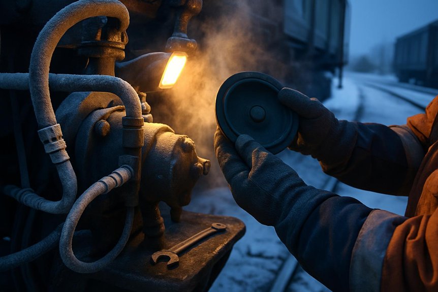
When ambient temperature drops below 10°F, treat brake diaphragm leakage as a cold-weather reliability risk. It is not a minor nuisance. Cold stiffens gaskets, diaphragms, and flange seals in locomotive brake systems. Service-worn brake systems may demand far more airflow. They can also lose brake cylinder pressure faster during extended applications.

Start with preventive replacement before severe winter service. Install winter-rated gaskets, seals, filters, and airline accessories. Do not reuse compressed, hardened, or cracked components. Verify locomotive compressors deliver clean, dry air. Moisture can accelerate freezing and leakage at pipe connections. Replace poor-performing brake cylinders with new or refurbished units. Take action when cold tests show abnormal flow demand.

Schedule pre-trip seal checks for diaphragms, flanges, and pipe connections. Pay extra attention before mountain routes or long-grade service. Use ultrasonic leakage detection where available. It can locate small cold-opened leaks before they become critical. Research on freight rail airbrakes presents ultrasonic leakage detection as an alternative to the soap and bubble test. Train locomotive crews on safe cold-weather handling. During severe conditions, use approved hand brake procedures for securement.

Follow AAR and FRA Leakage Test Rules

aar fra single car air tests

Cold-weather leak prevention works only when tests follow AAR and FRA rules for locomotive brake systems. Perform single-car air brake testing by interval. Use 12 months for manual S-486 tests. Use 24 months for automated S-4027 tests. Use 48 months for four-pressure S-4027 Section 13.0 tests. Test at 90 psi with qualified personnel. Follow 49 CFR § 232.305 procedures. Perform a single-car air brake test on each new or rebuilt car before placing or using it in revenue service.

Hold brake cylinder leakage for at least five minutes after a full-service application. Keep cylinder communication closed during the hold period. Use the gauge method with horizontal-or-higher pressure taps. Install new taps that comply with S-4020. Check brake pipe leakage after a 10-pound reduction from at least 70 psi. Leakage must not exceed 5 psi per minute. Limit main reservoir leakage to a 3 psi average over three minutes.

Trigger required tests after cylinder, hose, reservoir, valve, or pipe bracket work. Also test after wheel defects or missing brake-system records. Document all test interval tracking. Ensure Umler reporting within 24 hours after repair completion.

Frequently Asked Questions

How Long Does a Freight Brake Diaphragm Typically Last?

A freight brake diaphragm typically lasts around 736 days under normal locomotive operating conditions. Rubber life depends on air quality and maintenance discipline.

Inspection intervals vary by brake system type. Check WABCO systems every 368 days. Inspect DMU filtration systems every 500 days. For 26-C systems with air dryers, inspect every 1,840 days.

You can extend service life by controlling moisture, heat, and contamination. Clean, dry compressed air protects the diaphragm from early aging.

Watch for common failure signs during locomotive brake inspections. These include cracking, hardening, sludge, leakage, and slow brake response.

Replace the diaphragm before brake pressure drops to 60–70 PSI within minutes. Do not wait for complete brake failure. Mikura International supports reliable locomotive brake maintenance with quality-focused supply solutions.

Can Brake Diaphragms Be Rebuilt Instead of Replaced?

Usually, locomotive brake diaphragms should not be rebuilt. Replace them when torn, degraded, delaminated, or structurally compromised. During brake diaphragm inspection, verify housing condition, clamp integrity, corrosion, pitting, and shell distortion. For rebuild versus replace decisions, follow locomotive maintenance practices. Service only minor external issues temporarily, and never seal ruptures. Use diaphragm troubleshooting steps to isolate leaks and confirm pressure retention. Replace the chamber section if containment integrity is doubtful.

What Materials Are Freight Brake Diaphragms Made From?

Freight brake diaphragms use rubber compounds suited for locomotive braking systems. Common materials include NR, EPDM, NBR, neoprene, and reinforced FKM. The choice depends on heat, oil, ozone, and chemical exposure.

Most diaphragms include fabric mesh molded into the rubber. This reinforcement controls stretch and prevents ballooning under pressure. It also helps maintain sealing geometry during repeated brake cycles.

Neoprene layers can improve durability in changing locomotive operating conditions. Reinforced compounds are preferred for high flex-cycle demands and harsh service environments.

Material selection should consider pressure rating, contamination exposure, and service temperature. Compliance with relevant railway brake standards should also guide the final choice.

WABCO Air Compressor Head Gasket Kit for Locomotives – 85mm, Catalog Parts

WABCO Air Compressor Head Gasket Kit for Locomotives - 85mm, Catalog Parts

Welcome to Mikura International’s comprehensive guide on WABCO air compressor head gasket kits, specifically the 85mm variant, essential for maintaining the optimal performance of your locomotive’s air system. As a leading exporter of locomotive and marine engine parts, we understand the critical role these components play. This guide is designed for experts seeking to source reliable spare parts and gain deeper insights into their applications and maintenance.

Understanding the WABCO Air Compressor in Locomotives

Understanding the WABCO Air Compressor in Locomotives

The WABCO air compressor is a vital component in locomotive braking and auxiliary systems. It delivers the compressed air necessary for operating brakes, horns, and other pneumatic devices throughout the locomotive. These robust air compressors are designed for continuous operation in demanding environments, making them a standard in the rail industry. Regular maintenance and timely replacement of parts, such as the head gasket, are crucial for reliable performance.

What is a WABCO Air Compressor?

A WABCO air compressor is a reciprocating compressor designed to supply compressed air for various pneumatic systems on a locomotive. These compressors often come in single or twin cylinder configurations, depending on the air demand of the locomotive. The WABCO air compressor system includes a crankcase, cylinder, compressor head, and other critical parts. The robust design ensures durability and a consistent air supply, vital for safe and efficient train operation. Mikura International offers a wide range of WABCO catalog parts to keep your compressors running smoothly.

Key Components of the Compressor

The WABCO air compressor comprises several key components, including the cylinder, compressor head, crankcase, pistons, and valves. Crucial to its operation are the following elements:

  • The head gasket, which seals the cylinder head to the engine block, preventing air leakage and maintaining optimal compression.
  • The cylinder, where the air is compressed.
  • The compressor head, which houses the valves.
  • The crankcase, which supports the mechanical components.

Mikura International supplies original and new WABCO parts with material numbers for reliable repairs.

Importance of the Head Gasket in Locomotive Applications

The head gasket is a critical sealing component in the WABCO air compressor, preventing leakage of compressed air from the cylinder. It ensures that the air compressor maintains the necessary pressure for the locomotive’s braking and auxiliary systems to function correctly. A faulty head gasket can lead to reduced compressor efficiency, increased fuel consumption, and potential system failures. Mikura International offers a WABCO 85mm head gasket kit made with a high-quality gasket by WABCO with material, ensuring a reliable and long-lasting seal during installation.

Features of the 85mm Head Gasket Kit

Features of the 85mm Head Gasket Kit

Specifications of the 85mm Gasket Kit

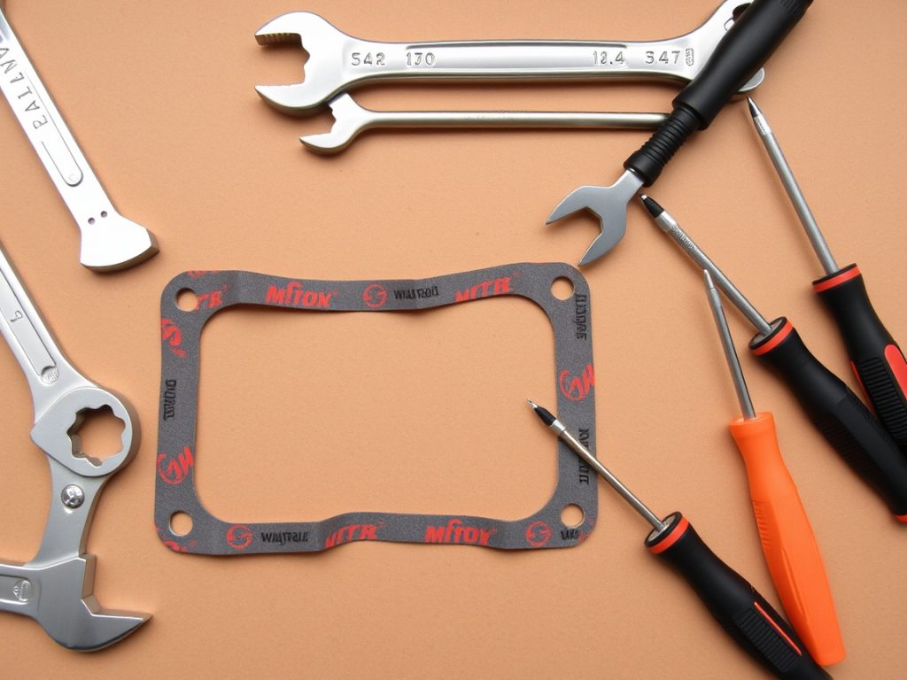
The WABCO 85mm head gasket kit from Mikura International features precise dimensions, adhering to the WABCO catalog specifications for optimal fit. The 85mm size refers to the inner diameter of the gasket, ensuring a perfect seal for compatible WABCO air compressor models. The kit includes a high-quality gasket, crafted with durable materials like reinforced steel and rubber compounds to withstand high pressures and temperatures. This ensures reliable performance and longevity of the air compressor.

Benefits of Using the WABCO Gasket Kit

Using the WABCO 85mm head gasket kit offers several benefits, especially in maintaining the air compressor’s efficiency. A new head gasket ensures a tight seal, preventing air leaks and maintaining optimal pressure within the cylinder. This, in turn, improves the performance of the locomotive’s braking and auxiliary systems. The kit from Mikura International helps reduce downtime and maintenance costs by providing a reliable, long-lasting solution. It guarantees that your WABCO air compressor operates at peak efficiency.

Comparative Analysis of Different Kits

When comparing different head gasket kits, it’s essential to consider the material, precision, and compatibility with your specific WABCO air compressor model. Mikura International’s WABCO 85mm head gasket kit stands out due to its high-quality construction and adherence to WABCO specifications with material numbers. Cheaper alternatives may use inferior materials, leading to premature failure and increased maintenance. Our kit ensures a reliable seal and optimal performance. It also comes with a warranty that ensures the quality.

Installation Guide for the Air Compressor Head Gasket

Installation Guide for the Air Compressor Head Gasket

Tools and Materials Needed for Installation

Before starting the installation of the air compressor head gasket, gather the necessary tools and materials. This includes a variety of items:

  • A socket set and wrench set, along with a torque wrench.
  • A scraper and cleaning solvent.
  • The new WABCO 85mm head gasket kit from Mikura International.

Make sure to have safety glasses and gloves to protect yourself during the process. Having a WABCO inform catalog handy can help in confirming parts, especially if working on older compressor models.

Step-by-Step Installation Process

The installation process starts with disconnecting the air supply to the WABCO air compressor. Then, remove the compressor head by unscrewing the bolts, being careful not to damage any components. Clean the mating surfaces of the cylinder and compressor head thoroughly using a scraper and solvent. Install the new WABCO 85mm head gasket, aligning it correctly. Reattach the compressor head and torque the bolts to the manufacturer’s specifications using a torque wrench. Finally, reconnect the air supply and test the compressor for leaks.

Common Mistakes to Avoid During Installation

One common mistake is failing to properly clean the mating surfaces, which can lead to a poor seal and air leaks. Another mistake is over-tightening or under-tightening the head bolts. Always use a torque wrench and follow the manufacturer’s specified torque settings. Avoid using excessive force when installing the new 85mm head gasket, as this can damage the material. Ensure the WABCO catalog number of the head gasket is correct for your air compressor model before starting the installation. Mikura International recommends consulting with a qualified technician if you are unsure about any step of the installation.

Maintenance Tips for WABCO Air Compressors

Maintenance Tips for WABCO Air Compressors

Regular Inspection and Maintenance Practices

Regular inspection and maintenance are crucial for the longevity of WABCO air compressors in locomotive applications. Check the compressor regularly for any signs of leaks, unusual noises, or vibrations. Inspect the air lines, fittings, and connections for any damage or wear. Ensure the compressor is properly lubricated according to the manufacturer’s recommendations. Cleaning the area around the WABCO compressor head can help prevent debris from entering the system, ensuring that you will not have to replace any parts regularly. Mikura International recommends following a strict maintenance schedule to prevent unexpected failures and ensure the compressor operates at peak efficiency.

Signs of Wear and Tear to Look Out For

Be vigilant for signs of wear and tear on your WABCO air compressor. Reduced air output, frequent cycling, and unusual noises are indicators of potential issues. Check for oil leaks around the compressor, which could indicate a failing seal or gasket, like the head gasket. Overheating can also signal problems with the compressor’s internal components. Inspect the air filter regularly and replace it as needed. Contact Mikura International if you observe any of these signs, so that you can get the WABCO inform catalog handy to make sure you are up-to-date with the parts. Addressing these issues promptly can prevent more significant damage and costly repairs.

Best Practices to Extend the Life of Your Compressor

To extend the life of your WABCO air compressor, implement best practices. Some examples of these practices include:

  • Maintaining proper lubrication levels and using high-quality lubricants.
  • Ensuring the air intake filter is clean to prevent contaminants from entering the compressor.

Periodically inspect and replace worn components, like the 85mm head gasket, before they cause major failures. Protect the compressor from extreme temperatures and harsh weather conditions. Mikura International offers a wide range of original and new WABCO parts to help you maintain your compressor in top condition. Implementing these practices will help ensure the reliability and longevity of your WABCO twin cylinder air compressor.

Sourcing WABCO Parts Through Mikura International

Sourcing WABCO Parts Through Mikura International

Why Choose Mikura International for Your Spare Parts

When sourcing WABCO parts, Mikura International stands out due to our commitment to quality and reliability. We offer a comprehensive selection of original and new WABCO parts with material numbers, including the 85mm head gasket kit. Our parts are sourced directly from reputable manufacturers, ensuring they meet stringent quality standards. With years of experience in the locomotive and marine engine part industry, we understand your needs and provide expert support to help you find the right parts quickly. By providing high-quality WABCO catalog parts, Mikura International guarantees that your Wabco compressor functions optimally.

How to Place an Order for the Head Gasket Kit

Placing an order for the WABCO 85mm head gasket kit from Mikura International is simple and efficient. Visit our website or contact our sales team directly to inquire about availability and pricing. Provide the specific details of your WABCO air compressor model to ensure compatibility. Our team will guide you through the ordering process and provide a detailed quotation. We offer flexible payment options and efficient shipping to ensure you receive your parts promptly. Mikura International makes acquiring your needed Wabco compressor head as easy as possible.

Customer Support and After-Sales Services

Mikura International is committed to providing exceptional customer support and after-sales service. Our knowledgeable team is available to answer your questions, provide technical assistance, and assist with any issues you may encounter. We offer warranty support on our WABCO parts, ensuring your satisfaction. We also provide guidance on installation and maintenance best practices to help you maximize the lifespan of your WABCO air compressor. Our commitment to customer satisfaction makes Mikura International your trusted partner for all your locomotive parts needs. We will make sure you know everything, from wabco catalog parts to a gasket by wabco with material.

Railway Train Brake Systems: Air Braked Freight Train Operation

Railway Train Brake Systems: Air Braked Freight Train Operation

Welcome to Mikura International’s comprehensive guide to railway train brake systems, specifically focusing on the intricacies of air braked freight train operation. As leading exporters of locomotive and marine engine parts, we understand the critical role of efficient and reliable braking systems in ensuring safe and productive railway transport. This guide delves into the essential aspects of air brakes, providing expert insights and actionable advice for professionals in the field.

Introduction to Train Brake Systems

Introduction to Train Brake Systems

Overview of Railway Brake Systems

Railway train brake systems are a cornerstone of safe train operation, acting as the control system to manage speed and prevent accidents. These systems have evolved significantly over time, with modern freight train applications heavily reliant on air pressure. The evolution has seen a shift from earlier systems like vacuum brakes to more reliable and efficient methods. Modern railway brake systems ensure controlled stops and prevent runaways.

Importance of Air Brakes in Freight Trains

The importance of air brakes in freight trains cannot be overstated; they provide a fail-safe, automatic brake mechanism throughout the train. An air brake system allows for synchronized braking across the length of the train, crucial for managing the immense weight and momentum of long trains. Unlike earlier systems, air brake systems offer superior control and reliability, ensuring the entire train responds predictably to brake application. Air brakes work by utilizing compressed air.

FeatureAir Brake System
SynchronizationSynchronized braking across the train’s length
OperationUtilizes compressed air

How Air Brakes Work

Air brakes rely on compressed air stored in a reservoir on each train car. The system’s operation involves both brake application and release, controlled by brake pipe pressure. Here’s a summary of the key processes:

ActionEffect
Engineer reduces brake pipe pressureBrakes are applied
Air pressure in brake pipe increasesBrakes are released and reservoir recharges

Specifically, when the engineer applies the brake, the brake pipe pressure decreases. This signals each car to apply its brakes, causing air from the brake reservoir to flow into the brake cylinder, pushing the brake shoe against the wheel.

Components of Air Brake Systems

Components of Air Brake Systems

Air Compressor: The Heart of the System

The air compressor is the heart of any air brake system, diligently working to provide the compressed air necessary for effective train operation. In the context of a freight train, a robust air compressor is essential to maintain the required air pressure in the brake reservoir. The air compressor continuously replenishes the air that is used to apply the brake and release the brake, ensuring the train brake systems have a consistent and reliable supply of compressed air. Without a fully functional air compressor, the train’s brakes would be compromised, posing significant safety risks. Mikura International offers top-quality air compressors designed for the demanding requirements of railway applications.

Brake Cylinder and Its Role

The brake cylinder is a critical component within the air brake system, acting as the actuator that converts air pressure into mechanical force to apply the brake. When the brake valve is activated, air pressure from the air reservoir flows into the brake cylinder. This brake cylinder pressure then pushes a piston, which in turn engages the brake shoe against the train car wheel, generating braking force. The size and design of the brake cylinder are carefully calibrated to provide the appropriate braking effort for different train configurations and operating conditions. The functionality of the brake cylinder is key to the application of the brakes throughout the train.

Understanding the Brake Valve Mechanism

The brake valve mechanism is the engineer’s primary control system for managing the train brake systems. The brake handle allows the engineer to control the pressure in the brake pipe, which directly affects the air brake system. By manipulating the brake handle, the engineer can vent the brake pipe, causing a brake pipe reduction that signals each car to apply the brake. The automatic brake valve ensures that the pressure in the brake pipe is maintained at the desired level. This maintains the air pressure which is critical for both applying and releasing the brakes. The brake valve offers precise brake control, crucial for safe and efficient freight train operation.

Operation of Air Braked Freight Trains

Operation of Air Braked Freight Trains

Setting Up the Air Brake System

Setting up the air brake system on a freight train involves a meticulous process to ensure the entire train operates safely and efficiently. This process begins with connecting the air hose between the train cars and ensuring proper connections. The train brake systems rely on maintaining consistent air pressure throughout the train, which is controlled by the brake valve. The air compressor is started to charge the air reservoir on each train car. Once the air pressure reaches the required level, a brake test is performed to verify that each brake cylinder is functioning correctly and that the brakes release properly. This thorough setup is critical for reliable train operation and to validate that the automatic brake is functional.

Monitoring Air Pressure for Safety

Monitoring air pressure is paramount to ensuring the safety of air braked freight train operation. The train brake systems depend on consistent air pressure throughout the length of the train. The engineer must continuously monitor the brake pipe pressure to detect any leaks or pressure drops, which could compromise braking force. Regular checks of the air reservoir levels and brake cylinder performance are also necessary. If air pressure falls below a critical threshold, the automatic brake system will activate, bringing the train to a controlled stop. Continuous monitoring is vital to preventing accidents. Mikura International emphasizes using reliable components to maintain proper air pressure in the air brake system.

Achieving Effective Braking Force

Achieving effective braking force in freight train operations requires a well-maintained and properly configured air brake system. The brake valve allows the engineer to precisely control the brake application and release. When the brake handle is engaged, compressed air is released from the brake reservoir into the brake cylinder. The pressure in the brake cylinder pushes the brake shoe against the wheels, generating braking force. The effectiveness of the braking system depends on maintaining adequate air pressure throughout the train, ensuring each brake cylinder responds uniformly. The entire train must respond to the brake handle.

Advantages of Air Braked Systems

Advantages of Air Braked Systems

Efficiency in Freight Train Operations

The efficiency of air braked systems in freight train operations is significant. Unlike older systems, air brakes provide a synchronized response across the entire train, regardless of its length. This synchronized brake application ensures that braking force is distributed evenly, reducing the risk of derailments and improving stopping distances. Key differences between air brakes and older systems are summarized in the table below:

Brake SystemKey Feature
Air BrakeSynchronized response across the entire train.
Vacuum BrakeOlder System (less efficient than Air Brake)

The air brake system’s reliable performance allows for smoother train operation, faster transit times, and increased overall productivity in freight transport. Mikura International provides components that contribute to more efficient train brake systems.

Enhanced Safety Features

Enhanced safety is a cornerstone advantage of air braked systems. The automatic brake feature ensures that any loss of air pressure in the brake pipe will automatically apply the brake. This fail-safe mechanism is crucial for preventing accidents in the event of a train car separation or a major air leak. Additionally, the ability to quickly apply full brake pressure provides superior control in emergency situations, reducing the risk of collisions. The reliability and responsiveness of the air brake system contribute significantly to the overall safety of freight train operations, protecting both cargo and personnel. Air brakes are crucial to a safe train operation.

Cost-Effectiveness of Maintenance

The cost-effectiveness of maintaining air braked systems stems from their relatively simple design and the wide availability of replacement parts. Regular maintenance checks are essential to ensure that the air compressor, brake valve, and brake cylinder function optimally. Addressing minor issues promptly can prevent more significant and costly repairs down the line. Air brake system components are designed for durability, and with proper care, they can provide years of reliable service. Mikura International offers high-quality replacement parts designed to maximize the lifespan and minimize the maintenance costs of air brake systems. Air brake repairs are very easy to perform.

Common Challenges and Solutions

Common Challenges and Solutions

Addressing Air Leak Issues

Air leak issues are a common challenge in railway train brake systems, particularly in long train consists, compromising the effectiveness of the air braked operation. Leaks in the air hose connections or within the air brake system components can lead to a drop in air pressure, reducing the braking force available. Regular inspections and maintenance, including checking the air reservoir and brake cylinder connections, are vital to identify and rectify leaks. Addressing air leaks promptly ensures that the entire train benefits from consistent brake pressure, enhancing safety. Maintaining the air system and fixing leaks will improve train operation.

Managing Brake Cylinder Failures

Brake cylinder failures can significantly impact the performance of train brake systems. These failures can manifest as a lack of braking force, delayed brake application, or complete inability to apply the brake. Regular inspections of the brake cylinder are critical, looking for signs of wear, corrosion, or damage. When a brake cylinder fails, it must be replaced with a high-quality component to ensure proper function. Proper maintenance and timely replacements maintain the effectiveness of the air braked operation and the safety of the train. Replacing the brake cylinder will greatly improve the train brake systems.

Improving Response Time of Brake Systems

Improving the response time of train brake systems is crucial for enhancing safety and operational efficiency. A slow response can increase stopping distances, posing a risk in emergency situations. Ensuring the air compressor is functioning optimally and maintaining adequate air pressure in the air reservoir are key factors. Upgrading to more responsive brake valve mechanisms and ensuring the brake pipe pressure is properly maintained can also improve response times. Efficient brake application throughout the whole train is crucial. A well-maintained and responsive air brake system ensures effective brake control, especially in freight train operations. The train brake systems will improve the braking system work of the railway.

Future Innovations in Train Brake Technologies

Future Innovations in Train Brake Technologies

Electronically Controlled Train Pneumatic Brakes

Electronically Controlled Pneumatic (ECP) brakes represent a significant advancement in train brake systems, offering enhanced control and responsiveness compared to traditional air braked systems. ECP train brake systems use electronic signals to communicate brake application commands throughout the train, allowing for near-instantaneous and synchronized brake activation on every train car. This technology significantly reduces stopping distances and improves brake control, leading to safer and more efficient train operation. This air brake system enhancement represents a pivotal shift in how train brake systems will function, offering precision and reliability.

Advancements in Automatic Air Brake Systems

Advancements in automatic brake systems focus on enhancing reliability and reducing maintenance. These advancements include improved sensors for detecting wheel slip, which allows for modulated brake application to prevent wheel lockup. Enhanced diagnostics are also being integrated to monitor the health of the air brake system and predict maintenance needs. Furthermore, self-adjusting mechanisms are being developed to maintain optimal brake shoe clearance, reducing wear and tear on the train’s brakes. These innovations promise to enhance the safety and cost-effectiveness of air braked freight train operations.

Impact of Technology on Freight Train Safety

Technology is poised to revolutionize freight train safety through advancements in train brake systems. Integration of GPS and advanced sensor technologies allows for real-time monitoring of train speed and location, enabling proactive brake application to prevent collisions. Enhanced automatic brake systems can detect and respond to abnormal conditions, such as broken rails or obstacles on the track. Moreover, data analytics can identify patterns and predict potential safety hazards, allowing for preventative maintenance and operational adjustments. These technological advancements promise to significantly reduce accidents and enhance the overall safety of railway operations. The safety of air brake systems is very important for train operation.

FAQ

Q: What is the role of compressed air in air braked freight train operation?

A: Compressed air is essential in air braked freight train operation as it is used to apply the brakes on the car. When the brake pipe pressure drops, air is sent from the reservoir to the brake cylinder, which activates the brake components and applies the brakes.

Q: How do electronically controlled pneumatic brakes differ from traditional braking systems?

A: Electronically controlled pneumatic brakes utilize electronic controls to optimize braking performance, allowing for more precise and efficient operation compared to traditional systems like the Westinghouse air brake, which relies solely on compressed air for braking action.

Q: What is a dynamic brake and how is it used in freight trains?

A: A dynamic brake is a type of braking system that uses the traction motors of the locomotive to slow down the train by converting kinetic energy into electrical energy. This method is often used in conjunction with the air brake system to enhance overall braking efficiency.

Q: What happens when the brake pipe pressure drops?

A: When the brake pipe pressure drops, it triggers the release of air from the reservoir to the brake cylinder, which results in the brakes being applied. This is a key feature that allows for synchronized braking across the length of the train.

Q: How do vacuum brakes function in comparison to air brakes?

A: Vacuum brakes operate by creating a vacuum in the brake pipe, which pulls the brake shoes against the wheels to slow down the train. In contrast, air brakes rely on compressed air to push the brake shoes into contact with the wheels. Each system has its advantages and is suited for different types of trains.

Q: What is the significance of the brake lever in train operations?

A: The brake lever is a crucial component that allows the conductor or engineer to manually apply or release the brakes. Moving the brake handle adjusts the amount of air to the brake cylinder, determining how effectively the brakes are applied.

Q: How do freight train braking systems ensure safety during operation?

A: Freight train braking systems, including compressed air systems and dynamic brakes, are designed with multiple redundancies and safety features. This ensures that even if one component fails, the remaining systems can still function to safely slow or stop the train.

Q: What is the role of the rear of the train in braking systems?

A: The rear of the train plays a crucial role in braking systems, as it is where the last car’s brakes are applied. The synchronization of braking from the front to the rear ensures that the entire train stops smoothly and safely.

Q: How do brake components interact during the braking process?

A: During the braking process, various brake components work together to achieve effective braking. When air is sent from the reservoir to the brake cylinder, it activates the brake shoes, which press against the wheels, thereby applying the brakes on the car and slowing down the train.

How to Detect Train Compressed Air Leaks

How to Detect Train Compressed Air Leaks

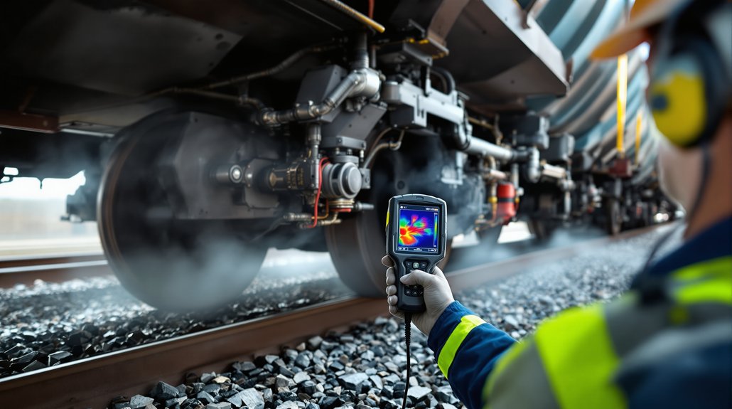
You can detect train compressed air leaks using ultrasonic acoustic imaging systems that identify leak signatures in the 30-45 kHz frequency range. These automated systems safely detect leaks from distances up to 130 meters without requiring dangerous manual inspections under moving equipment. Modern acoustic imagers with 64-128 microphones achieve 84.6% detection accuracy while eliminating worker exposure to hazardous rail environments. The technology generates real-time electronic alerts with precise leak locations and severity ratings for immediate maintenance response coordination.

Key Takeaways

  • Use ultrasonic detection equipment to identify acoustic signatures between 30-45 kHz frequencies where compressed air leaks produce distinct sound patterns.
  • Deploy acoustic imager technology with microphone arrays to visually locate leaks from safe distances of 5-10 feet without system shutdowns.
  • Install strategic sensor networks across critical pneumatic components like brake lines, door operators, and suspension systems for continuous monitoring.
  • Implement machine learning algorithms that analyze pressure and acoustic data to distinguish normal fluctuations from anomalous consumption indicating leaks.
  • Combine thermal imaging devices with ultrasonic sensors to detect leaks as small as 0.016 l/min while reducing inspection time by 90%.

Manual Detection Challenges in Railroad Operations

hazardous manual air leak detection

When railroad personnel manually detect compressed air leaks, they’re forced to navigate hazardous environments that expose them to significant safety risks. You’ll encounter moving train components, heavy machinery, and confined spaces around locomotives and rail cars during these inspection procedures. The physical demands of crawling under and between railway vehicles create serious inspection ergonomics challenges that can compromise both safety and detection accuracy.

Traditional detection methods require you to listen for compressed air escape sounds or feel for leaks while positioned in potentially dangerous locations. These time-intensive processes can take hours or days, leading to worker fatigue that further increases safety risks. Your detection accuracy depends heavily on experience and hearing ability, while background noise from train operations often masks smaller leaks. Weather conditions and environmental factors additionally impair your effectiveness, making manual detection both unreliable and hazardous for maintenance personnel. The rail industry loses an estimated 2–3% vehicle efficiency annually due to these undetected air leaks.

Automated Audio Detection Technology Solutions

You’ll find that modern automated audio detection systems leverage sophisticated acoustic imager technology to identify compressed air leaks without requiring manual inspections. These systems integrate machine learning algorithms that analyze frequency signatures between 30-45 kHz, where compressed air leaks produce distinct acoustic patterns separable from background railway noise. Your detection capabilities improve markedly through this technology, achieving detection rates of 11 out of 13 leaks with false positive rates as low as 0.03% during operational testing. The technology addresses significant efficiency losses in the rail industry, where compressed air leaks typically reduce vehicle efficiency by 2% to 3%.

Acoustic Imager Technology

Acoustic imaging technology transforms compressed air leak detection by combining ultrasonic sensors with visual cameras to pinpoint leaks in real-time. You’ll achieve precise acoustic mapping through advanced sensor calibration that eliminates background noise interference common in railway environments.

Equipment ModelSensor CountDetection Range
FLIR Si124124 microphonesUp to 120 meters
CRYSOUND128 MEMS sensorsExtended distance
Standard Units64-96 sensors50-80 meters
Compact Models32-48 sensors25-40 meters

The technology detects leaks as small as 0.016 l/min while overlaying ultrasonic data onto visual images. You’ll reduce inspection time by 90% compared to traditional methods. Equipment operates safely from distances without requiring system shutdowns, making it ideal for continuous railway operations where safety protocols demand non-invasive detection methods. This visual ultrasound approach transforms sound into visual data, enabling inspectors to identify compressed air system inefficiencies that would otherwise remain hidden during routine maintenance checks.

Machine Learning Integration

While traditional acoustic detection relies on manual interpretation, machine learning algorithms now automate compressed air leak identification by processing ultrasonic frequency data in the 30-45kHz range where leaks produce distinct signatures above background railway noise. You’ll train these AI systems using hydrophone recordings with verified leak and non-leak examples, incorporating variables like gun volume, pressure, and depth configurations. The algorithms process incoherent signal distortions that classical methods can’t define effectively.

Your implementation requires robust data governance protocols to guarantee training dataset quality and regulatory compliance. Model explainability becomes critical when justifying maintenance decisions to stakeholders. You’ll integrate these systems with existing flow sensors and control infrastructure, generating real-time electronic alerts with visual documentation. This approach enables continuous monitoring without operational shutdowns while providing predictive maintenance capabilities through IoT connectivity. Advanced systems utilizing 64-microphone arrays can achieve detection rates of 11 out of every 13 leaks on moving trains.

Detection Performance Metrics

Machine learning algorithms require quantifiable performance benchmarks to validate their effectiveness in operational railway environments. You’ll achieve 84.6% accuracy rates when detecting compressed air leaks on moving trains, maintaining false positive rates at just 0.03% during field operations. Your system will identify approximately 11 out of every 13 leaks during moving evaluations, with performance improving through additional data collection.

Proper sensor calibration guarantees detection from 2.5 meters for small leaks up to 130 meters for larger ones. Environmental effects don’t compromise your ability to detect minimum leak sizes of 0.01 liters per minute. You’ll receive confidence ratings for each identified leak location, enabling maintenance personnel to prioritize repairs effectively. Field testing demonstrates successful detection across 30-40 leaks within operational timeframes. The acoustic sensor operates within 30-45 kHz frequencies where compressed air leak signatures are most distinguishable from background noise.

Acoustic Imaging Equipment and Frequency Analysis

ultrasonic acoustic leak imaging

Transform sound waves into precise visual data using acoustic imaging cameras that detect ultrasonic frequencies generated by compressed air leaks on railway equipment. These specialized cameras utilize MEMS arrays containing multiple microphones to capture high-frequency acoustic signals that turbulent air creates when escaping from pneumatic systems.

You’ll achieve peak detection by operating within the ultrasonic bandwidth range where compressed air leaks generate their strongest acoustic signatures. The carefully constructed MEMS arrays provide high sensitivity imaging that overlays ultrasonic information onto visual camera feeds in real time.

Advanced models like the FLIR Si2-LD enable detection from distances up to 130 meters, ensuring safe inspection of energized train systems. The equipment’s noise suppression technology filters background industrial sounds, allowing you to identify leak sources precisely even in noisy rail yards. This acoustic imaging approach reduces inspection time by approximately 90 percent compared to traditional ultrasonic detection methods. Modern acoustic cameras feature onboard analytics that automatically calculate financial losses from each detected leak, enabling immediate cost-benefit analysis for repair prioritization.

Multi-Sensor Integration With Machine Learning

multi sensor machine learning leak detection

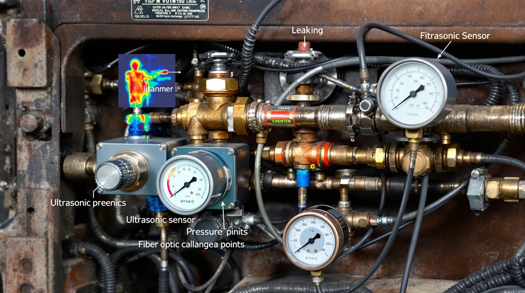
Acoustic imaging cameras provide powerful standalone detection capabilities, yet combining multiple sensor technologies with machine learning algorithms creates complete leak detection systems that surpass single-sensor performance. You’ll achieve peak results by integrating ultrasonic sensors, pressure transducers, and thermal imaging devices through strategic sensor placement across critical pneumatic components.

Machine learning algorithms process multi-sensor data streams to identify leak patterns that individual sensors might miss. You can implement data augmentation techniques to expand training datasets, improving algorithm accuracy for detecting subtle pressure variations and acoustic signatures specific to railway compressed air systems.

Smart sensor networks enable real-time monitoring of brake lines, door operators, and suspension systems simultaneously. You’ll benefit from automated alert systems that distinguish between normal operational sounds and actual leaks. Advanced algorithms learn your specific train fleet’s acoustic fingerprints, reducing false positives while ensuring critical safety systems maintain proper pressure levels for reliable braking and door operation.

Establishing a compressed air baseline through thermal mass flowmeters enables precise measurement of your system’s consumption patterns before implementing leak detection protocols. Machine learning models use this baseline data to distinguish between normal operational fluctuations and anomalous consumption indicating potential leaks throughout the pneumatic network.

Performance Metrics and Detection Accuracy Rates

accurate ultrasonic leak detection

When evaluating compressed air leak detection systems for railway applications, you’ll find that current automated technologies achieve an 84.6% overall accuracy rate in identifying leaks on moving trains. These systems successfully identify 11 out of every 13 leaks during operational testing, ensuring regulatory compliance with safety standards while reducing environmental impact through energy conservation.

You can expect detection capabilities ranging from 0.01 liters per minute for small leaks at close range to extensive scanning at distances up to 130 meters. The false positive rate remains exceptionally low at 0.03%, which prevents unnecessary maintenance interventions and maintains operational efficiency. Modern handheld systems utilize 96 ultra-sensitive microphones to capture ultrasonic sound waves that indicate air leaks in railway brake systems.

Machine learning algorithms demonstrate consistent performance in distinguishing actual leaks from background noise across 2 to 100 kHz frequency ranges. Your maintenance teams can identify and repair 30 to 40 leaks within hours using these systems, markedly improving both safety protocols and environmental stewardship through reduced compressed air waste.

Alert Systems for Maintenance Personnel

automated precise leak alerts

Modern compressed air leak detection systems automatically generate and transmit electronic alerts to your maintenance personnel the moment they identify leaks on moving trains. These automated notifications eliminate dangerous manual inspection procedures while providing precise location coordinates and severity assessments through real time dashboards and mobile alerts.

Your alert system delivers thorough data packages containing:

  1. Total leak count per inspection cycle with confidence levels
  2. Precise coordinates and positioning data for each detected leak
  3. Visual documentation from integrated cameras highlighting specific leak locations
  4. Technical specifications including severity ratings and detection frequency ranges

You’ll receive instantaneous notifications through digital communication channels, enabling immediate response coordination without stopping trains. The system integrates seamlessly with existing maintenance workflows, allowing proactive scheduling and targeted interventions. Mobile alerts ensure your personnel can assess situations remotely before on-site inspection, reducing labor requirements and minimizing exposure to hazardous environments while maximizing maintenance efficiency. These autonomous detection systems also contribute to reduced fuel consumption by identifying air leaks that would otherwise force locomotives to work harder to maintain proper air pressure levels.

Field Testing Results and System Validation

high accuracy multi sensor leak detection

Through rigorous field testing protocols, the compressed air leak detection system achieved an 84.6% accuracy rate while maintaining exceptional reliability with false positives occurring in only 0.03% of test scenarios. You’ll find the system successfully identifies 11 out of every 13 leaks during moving train operations, demonstrating operational readiness for regulatory compliance requirements.

The multi-sensor integration combines thermal, acoustic, and visual spectrum imaging with Fluke SV600‘s 64-microphone array detecting frequencies between 30-45kHz. You can detect leaks as small as 0.01 litres per minute from 2.5 meters distance, ensuring all-encompassing coverage across locomotive locations.

Machine learning algorithms filter background noise interference while maintaining detection accuracy during dynamic train operations at various speeds. The system’s long term durability has been validated through extensive environmental condition testing, confirming performance consistency across multiple operational scenarios and supporting deployment readiness for rail yard environments. Detection systems should target maintaining leakage below 10% of total compressed air production to optimize energy efficiency and operational costs.

Implementation Benefits for Rail Yard Efficiency

automated compressed air leak detection

You’ll experience significant operational improvements when implementing automated compressed air leak detection systems in your rail yard operations. Your maintenance teams won’t need to conduct time-consuming manual searches that require dangerous positioning on, under, or between railway vehicles, reducing both labor costs and safety risks. You can respond faster to system issues since real-time detection identifies problems immediately, allowing your crews to address small leaks before they escalate into costly major repairs.

Reduced Labor Requirements

While traditional compressed air leak detection demands significant manual labor from your mechanical staff, automated ultrasonic systems dramatically reduce these workforce requirements by eliminating the need for physical inspections. Your staff reduction becomes immediately apparent when considering that manual detection requires employees to physically search locomotives by going on, under, or between railway vehicles. Workflow optimization occurs through automated detection on moving trains without human intervention.

Key labor reduction benefits include:

  1. Minimal Training Requirements – Only 2 hours needed for ultrasonic detection proficiency
  2. Automated Notifications – Direct alerts to mechanical personnel eliminate manual searching
  3. Remote Detection Capability – 5-10 foot range eliminates close proximity requirements
  4. High Detection Accuracy – 11 out of 13 leaks detected automatically without staff investigation

Faster Maintenance Response

Automated ultrasonic detection systems accelerate your maintenance response times by delivering real-time leak alerts directly to mechanical personnel the moment compressed air leaks occur on moving trains. You’ll receive electronic notifications containing exact leak locations, system confidence levels, and accompanying images that eliminate time-consuming search procedures. This immediate data transmission enables faster dispatch of repair crews to specific problem areas rather than conducting broad inspections across entire systems.

The digital alert system supports priority routing by categorizing leak severity levels, allowing you to allocate resources efficiently based on operational impact. Your maintenance teams can coordinate responses immediately between detection and repair operations, preventing minor leaks from escalating into major system failures that require extended downtime and costly emergency repairs.

You may also like to read – How to Fix Locomotive Air System Gasket Problems

Frequently Asked Questions

What Is the Typical Cost to Install an Automated Air Leak Detection System?

You’ll face installation costs ranging from $2,000-$15,000 for automated air leak detection systems, depending on complexity and integration requirements. Basic semi-automatic platforms start around $2,000, while fully automated systems with custom fixtures, sensors, and control interfaces reach $15,000+. Factor in ongoing subscriptions for software updates, calibration services, and technical support that typically add 10-15% annually to your initial investment for optimal safety performance.

How Long Does It Take to Train Personnel on the New Detection Equipment?

Like mastering a new instrument, you’ll need dedicated practice time to become proficient. Training duration depends on your chosen format—hands on workshops typically require one to two days for thorough equipment mastery, while virtual modules can be completed in six hours for basic competency. Advanced detection systems demand prerequisite training plus hands-on experience. You’ll achieve certification once you pass the 80% assessment threshold.

Can the System Work Effectively in Extreme Weather Conditions Like Snow or Rain?

You’ll need weatherized components for reliable operation in extreme conditions. Cold weather affects seals, requiring low-temperature materials that won’t crack or harden. Install drain heaters to prevent moisture freeze-up in detection lines and instrument housings. You must verify all sensors maintain calibration accuracy below freezing and make certain protective enclosures meet IP ratings for rain penetration. Regular winter maintenance protocols become critical for consistent leak detection performance.

What Maintenance Schedule Is Required to Keep the Acoustic Sensors Properly Calibrated?

Like a finely tuned orchestra requiring regular conductor guidance, you’ll need monthly functional tests, quarterly verification checks, and annual full-system calibrations. You must perform weekly operational checks and daily visual inspections. Temperature compensation occurs every six months, while vibration baselines need monthly updates. Your sensor recalibration intervals depend on environmental exposure severity. Make certain your technician certifications renewal stays current, as proper calibration requires certified personnel following ISO standards for measurement accuracy.

How Does Detection Accuracy Compare Between Stationary Trains Versus Moving Trains?

You’ll achieve higher stationary accuracy rates compared to moving train detection due to controlled environmental conditions. Moving variability introduces background noise, vibrations, and positioning challenges that reduce the current 84.6% accuracy rate. When you inspect stationary trains, you’ll eliminate motion-related interference, allowing closer sensor positioning and more precise leak identification. You’ll experience fewer false readings and improved component-by-component examination capabilities during static inspections.

How to Fix Locomotive Air System Gasket Problems

How to Fix Locomotive Air System Gasket Problems

You’ll solve most locomotive air system gasket problems by targeting the gladhand connections and brake pipe assemblies where eighty percent of pressure losses occur within the final thirty feet of your trainline. First, confirm zero system pressure before disconnecting any components, then inspect gladhand gaskets for visible damage or contamination that compromises sealing. Replace deteriorated gaskets using proper torque specifications, clean mating surfaces thoroughly, and hand-tighten connections an additional half-turn after initial seating. Advanced diagnostic techniques and preventive maintenance protocols can further optimize your system’s reliability.

Key Takeaways

  • Replace gaskets immediately when control valve gasket failure is suspected to prevent brake system malfunctions.
  • Focus repairs on gladhand gasket connections, the primary source of pressure loss in locomotive air systems.
  • Ensure proper gasket seating by checking surface contact and hand-tightening connections with a half turn.
  • Inspect and clean gasket surfaces for contamination that could impede proper sealing before installation.
  • Conduct pressure testing to verify brake pipe leakage stays under 5 lbs/min after gasket replacement.

Identifying Natural Leakage Sources in Trainline Connections

gladhand gasket leakage in trainline

When operating locomotive air brake systems, you’ll encounter natural leakage through gladhand gasket connections that represents the primary source of pressure loss in trainline operations. You’ll need to inspect gasket wearpatterns at each connection interface to identify deterioration pathways. Focus your detection efforts on the air brake compartment below the locomotive cab and rear sander magnetic valve areas where eighty percent of leaks occur within the final thirty feet before end-use application.

Check for ambient moisture accumulation around connection points, as this indicates active air escape routes. You’ll find that vibrations and thermal cycling cause fittings to loosen, creating continuous air loss pathways throughout the train consist. Monitor trainline pressure drops when engines shut down—gradual pressure loss below minimum acceptable rates prevents automatic brake application. Leakage rates increase significantly as temperature drops, making cold weather inspections particularly critical. Examine threaded pipe connections more thoroughly than welded systems, as they’re prone to leakage from improper thread sealants and environmental contamination.

Systematic Air Leak Detection and Diagnostic Procedures

automated acoustic thermal leak detection

Although manual detection methods remain standard practice across most rail operations, you’ll achieve superior diagnostic accuracy by implementing systematic leak detection protocols that combine automated sensing technology with structured inspection procedures. Automated detection systems utilizing acoustic imaging technology can identify air leaks with 84.6% accuracy while maintaining false positive rates of only 0.03%. You’ll need to configure acoustic imagers operating at 30-45kHz frequencies, where compressed air leaks stand out distinctly from background machinery noise.

Integrate multi-camera arrays combining acoustic imaging with thermal and visual spectrum cameras to generate composite diagnostic images. The FLIR Si1-LD‘s 96-microphone array detects leaks as small as 0.01 liters per minute from 2.5 meters distance. You should establish standardized inspection sequences that eliminate manual searching procedures, reducing personnel exposure risks while ensuring Federal Railroad Administration compliance. Machine learning algorithms will progressively improve detection accuracy through continued field data collection and system refinement. Implementing these automated systems can reduce the locomotive industry’s fuel consumption by addressing the estimated 2-3% vehicle efficiency loss that occurs annually due to undetected air leaks.

Component-Specific Gasket Failure Analysis

gasket failure from contamination

You’ll encounter three critical failure patterns when analyzing component-specific gasket deterioration in locomotive air systems. Pneumatic valve gaskets fail primarily due to thermal cycling stress and contamination buildup, while cylinder head lacquer deposits indicate oil system contamination that compromises sealing surfaces. Triple valve malfunctions typically result from seal degradation that prevents proper pressure regulation, requiring immediate inspection of gasket integrity and replacement per 49 CFR Part 229 safety standards. Begin inspection with oil hole and journal fillet checks, where 68% of failures occur.

Pneumatic Valve Gasket Deterioration

Since pneumatic valve gaskets endure constant pressure cycling and mechanical stress in locomotive air systems, you’ll encounter specific failure patterns that directly compromise braking performance and operational safety. You must assess material compatibility between gaskets and locomotive operating fluids to prevent chemical degradation. Thermal cycling accelerates elastomer breakdown, reducing sealing effectiveness during temperature fluctuations.

Monitor for hissing sounds near valve connections, which indicate gasket deterioration and air leakage pathways. Pressure drops signal gasket compression failures at suction valve covers. Contamination through inlet, outlet, and vent ports degrades gasket integrity when inadequate filtration allows debris accumulation. Apply soapy solution to suspected leak points and watch for bubbling to confirm gasket failure locations. Implement proper maintenance schedules to prevent harmful substance buildup that accelerates gasket wear patterns and creates valve sealing failures.

Cylinder Head Lacquer Deposits

While pneumatic valve gasket failures present immediate operational concerns, cylinder head lacquer deposits create a different category of gasket deterioration that develops gradually through combustion-related processes. You’ll encounter cylinder lacqueration when partially combusted fuel components condense on liner surfaces, undergoing oxidation that creates hard, sticky residues. These deposits fill honing grooves, creating glazed surfaces that prevent proper gasket sealing.

Monitor oil consumption rates and conduct surface roughness measurements to detect lacquer formation early. For varnish mitigation, implement regular cleaning protocols using correctly-tailored chemistry before deposits harden. When lacquer accumulation compromises gasket integrity, you’ll need complete engine overhaul with liner rehoning for effective restoration. Acid cleaning may provide temporary relief, but remaining deposits often become nucleation sites for renewed formation. Engines operating under mixed load regimes show increased susceptibility to this type of gasket-compromising lacquer development.

Triple Valve Malfunctions

When triple valve gaskets fail, you’re dealing with a critical component that controls both service and emergency braking systems across your entire train consist. Natural leakage through gladhand gasket connections causes trainline pressure drops, preventing automatic brake setting despite pressure loss. Single valve failure compromises your entire train’s stopping power during operation.

You’ll face valve balancing issues when New York Airbrake DB-10 components exceed their useful life. Spring fatigue compounds problems as lubricants dry up and gaskets become brittle. Emergency reservoir pressure drops from 90 psi, affecting both chambers simultaneously.

Replace valves every eight years by removing three bolts and installing new gaskets. Clean components with appropriate solvents, apply Rocol 1000 lubricant to slide valves, and use W.H.B. grease on gasket surfaces for peak performance. The triple valve compares brake pipe pressure and reservoir pressure to select RELEASE, APPLY, or LAP positions for proper brake operation.

Inspection Protocols for Critical Pneumatic Components

gasket degradation in pneumatics

Before you commence any pneumatic system maintenance, you must establish rigorous inspection protocols that systematically evaluate each critical component’s operational integrity and safety compliance. During routine inspections, examine air compressor assemblies, reservoir tanks, control valves, and brake chambers for gasket compatibility issues and structural degradation. You’ll need to inspect piston pin bushings, piston rings, cylinder walls, and pistons for lacquer deposits that indicate lubricant breakdown affecting gasket performance.

Check discharge valves for lacquer accumulation and carbon deposits, which compromise gasket sealing effectiveness. Evaluate magnet valves, brake valves, and feed valves for lacquer qualification standards. Document all maintenance activities and component conditions during inspection procedures, noting gasket wear patterns and replacement requirements.

Monitor oily substance formation in feed valves indicating potential oil distillation that can deteriorate gasket materials. Establish inspection intervals consistent with operational demands while maintaining thorough documentation for regulatory compliance and component lifecycle management. Perform comprehensive pressure testing to ensure brake pipe leakage remains under 5 lbs/min and main reservoir leaks stay under 3 lbs/min, as gasket deterioration directly impacts these critical pressure thresholds.

Gasket Replacement and Repair Techniques

locomotive air system gaskets

Execute gasket replacement procedures systematically to maintain locomotive air system integrity and prevent catastrophic pressure failures. You’ll need specialized installation tools including internal pliers for retainer rings and anvil fixtures for proper alignment. Verify gasket materials meet AAR specifications and withstand system pressures up to 550 kPa before installation.

  • Remove clamp assemblies carefully when accessing suction valve gaskets to prevent damage to sealing surfaces
  • Position upper and lower unloader plunger gaskets correctly during valve reassembly using proper torque specifications
  • Press roller bearings into piston assemblies without overcompressing gasket seals that could cause premature failure

When installing new gaskets on cover plates, rotate piston components 180 degrees to make certain even seating pressure. Place piston assemblies over anvil fixtures to maintain proper gasket alignment throughout the process. Remove installation plugs carefully to prevent damage to newly installed gaskets during final assembly procedures. Follow ASME PCC-1 installation procedures and proper bolt-tightening sequences to avoid under- or over-compression that can compromise seal effectiveness.

Preventing Lacquer Deposits and Contamination Issues

prevent lacquer from oil contamination

Why do locomotive air systems fail prematurely despite proper gasket installation? You’re likely dealing with contamination issues that compromise system integrity. Heavy detergent oils form hard lacquer deposits on cylinder heads and walls, causing oil carryover throughout your system. These unsuitable oils contain unstable compounds that distill off and deposit at expansion areas like feed valves.

Focus on proper lubricant selection to prevent lacquer formation. Avoid heavy weight oils that cause excessive piston pin bearing wear and system contamination. When you discover oily substances in feed valves, you’re facing oil distillation issues, not compressor pumping problems. Regular upkeep detects and addresses leaks that could harm engine and structure before they escalate into costly system failures.

Implement rigorous filtration maintenance protocols. Examine magnet valves, brake valves, and discharge valves for lacquer accumulation during qualification testing. Inspect piston pin bushings, rings, cylinder walls, and pistons for deposits. Install efficient filtering systems, dryers, and coolers to maintain contamination-free compressed air essential for tank-car pressurization operations.

Maintaining Optimal System Pressure and Performance

monitor calibrated asme gauges

You’ll need to implement systematic pressure monitoring techniques to ensure your locomotive’s air system operates within manufacturer specifications throughout each service cycle. Start by installing ASME Grade 2A pressure gauges at critical system points and establish regular calibration intervals to maintain measurement accuracy. Focus your performance optimization methods on maintaining continuous flow rates while preventing pressure deviations that could compromise brake cylinder function or overall system integrity. Poor gasket sealing allows contaminated compressed air to enter the system, causing component slowdown and accelerated failure of critical pneumatic functions.

Pressure Monitoring Techniques

Within locomotive air brake systems, you’ll establish proper pressure monitoring through systematic verification of operating parameters and continuous assessment of system integrity. Deploy JUMO MIDAS S19 R pressure transmitters for real time diagnostics of fuel feed pressure and rail pressure systems. These instruments enable predictive maintenance by tracking lubricating oil pressure and turbocharger charge-air pressure continuously.

  • Calibrate testing gauges every 92 days to maintain accuracy within 3 psi of locomotive brake pipe gauge at 90 psi
  • Configure warning devices to activate at 55 psi for immediate low air pressure condition alerts
  • Conduct standard leakage tests using one-minute intervals with maximum allowable rates not exceeding 5 psi per minute

You’ll verify proper charging requires pressure within 15 psi of operating pressure, while cut-out testing ensures maximum thresholds don’t exceed 145 psi.

Performance Optimization Methods

Optimize locomotive air brake system performance by implementing exhaustive energy management strategies that integrate regenerative braking capabilities with intelligent power controls. You’ll achieve maximum efficiency through aerodynamic optimization techniques that reduce system drag and enhance airflow dynamics around critical components. Install high-flow mufflers and properly sized exhaust piping to minimize back pressure throughout your air system network.

Execute regenerative integration protocols by upgrading turbocharger assemblies and exhaust manifolds for improved scavenging efficiency. You must monitor real-time pressure differentials while adjusting automated throttle controls during operational cycles. Implement spiral louvered mufflers to reduce restrictions and boost overall system output. Follow AAR specifications M-60l-7l for air hose performance standards. Maintain proper coupling engagement through systematic inspection procedures to assure reliable connections and prevent catastrophic pressure loss during critical braking operations.

Emergency Brake System Gasket Troubleshooting

brake pipe gasket inspection

Before attempting any emergency brake system gasket repairs, you must establish proper safety protocols and verify complete system depressurization. Emergency diagnostics start with identifying sudden pressure drops that trigger emergency brake applications throughout the consist. When brake pipe pressure drops to zero, you’ll experience a complete dump of all 90psi from charged systems.

Focus your emergency diagnostics on brake pipe connections at hose glad hands, as these flexible connections between cars represent the most common failure points. Examine air hose and coupling assemblies, including hose coupling, clamps, and pipe nipple attachments to car brake pipes.

  • Confirm zero system pressure before disconnecting any air lines or components
  • Inspect brake pipe connections at glad hands for visible damage or contamination
  • Verify proper gasket seating by checking surface contact and hand-tightening half turn

Control valve malfunctions prevent proper brake application and release during emergencies, requiring immediate gasket replacement and surface preparation verification.

Frequently Asked Questions

What Specific Gasket Materials Work Best in Extreme Temperature Railroad Operating Conditions?

Like armor against temperature’s relentless assault, you’ll need specialized materials engineered for extreme conditions. Deploy Viton seals for fuel and hydraulic systems—they’ll withstand chemical aggression and thermal cycling from -20°F to 400°F. Install PTFE gaskets in high-temperature applications where standard elastomers fail. For pneumatic brake systems, you must specify EPDM compounds that maintain sealing integrity through freeze-thaw cycles while ensuring consistent braking performance and operational safety.

How Often Should Locomotive Air System Gaskets Be Replaced During Routine Maintenance?

Replace air system gaskets at scheduled intervals every 368 days during regulatory compliance inspections, but you’ll need condition-based replacement when pressure drops exceed 10 psi or contamination occurs. You must inspect triple valve gaskets during systematic cleaning cycles and replace filter gaskets immediately upon pressure differential indicators. Don’t wait for scheduled intervals if you observe lacquer deposits, moisture damage, or seal degradation during daily brake checks.

Can Temporary Gasket Repairs Be Safely Made During Remote Breakdowns?

You can’t safely perform temporary repairs on locomotive air system gaskets during remote breakdowns. Field improvisation compromises system integrity and violates safety protocols. Instead, you’ll need to depressurize the system, isolate affected sections using cut-out cocks, and transport defective components to authorized workshops. Use wood covers and defective hose material for temporary protection only during transit, never as functional gasket replacements.

What Tools Are Required for Proper Gasket Installation in Locomotive Brake Systems?

You’ll need specialized gasket installation tools including the glad hand gasket 2-in-1 tool and window locking gasket tool set with pry tools. Always follow proper torque sequence specifications when tightening fittings. Clean all mating surfaces with approved cleaning solvents before installation. Don’t use basic hand tools—they’re insufficient for brake work. Make sure you’ve got proper gauges to verify leak-tight installations and maintain system integrity.

How Much Does Professional Gasket Replacement Typically Cost for Locomotive Air Systems?

You’ll typically pay $150-300 for professional gasket replacement, including labor rates of $75-120 hourly and parts markup of 15-25% above wholesale. Basic pneumatic valve gaskets cost under $200 with thirty-minute service intervals. Don’t attempt DIY repairs—improper installation compromises system integrity and FRA compliance. Enhanced sealing solutions carry higher upfront costs but reduce maintenance frequency. Always verify technician certification before authorizing work on critical brake system components.

How to Replace Brake System Membranes in Locomotives

How to Replace Brake System Membranes in Locomotives

You’ll start by applying spring brakes and conducting safety briefings before removing the triple valve cover and extracting piston assemblies in precise sequence. Clean all components with approved brake cleaner, inspect membranes for damage, and verify material compatibility with housing specifications. Position new membranes with sealing lips facing correctly, apply recommended lubricants sparingly, and torque retaining rings to 45-65 ft-lb. Complete pressure testing within regulatory parameters and document everything on Form F6180-49A. Mastering these systematic procedures guarantees peak brake performance and regulatory compliance.

Key Takeaways

  • Apply spring brakes, place wheel chokes, and conduct safety briefing before beginning membrane replacement procedures.
  • Identify membrane type (triple valve, pneumatic seal, or brake cylinder) using part numbers and dimensional specifications.
  • Remove triple valve cover first, then extract piston assembly following precise sequence to protect machined surfaces.
  • Select compatible membrane materials (NBR, Viton, EPDM) based on operating temperature and fluid compatibility requirements.
  • Test system pressure build-up from 80-100 psi within two minutes and verify cut-out pressure stays below 145 psi.

Pre-Replacement Inspection and System Preparation

thorough locomotive brake system inspection

Before replacing locomotive brake membranes, you must conduct thorough system verification to guarantee safe working conditions and identify potential complications that could affect the replacement process. Start with vehicle securing by applying spring brakes and placing wheel chocks on level ground surfaces. Verify complete brake release functionality through pull-by inspection procedures performed by certified car inspectors.

Conduct an all-inclusive safety briefing covering system isolation procedures and emergency protocols. Complete your tool inventory, making certain testing gauges meet 92-day calibration requirements with 3 psi tolerance accuracy. Perform visual inspection of brake cylinders, checking for damaged or loose components requiring immediate correction. Execute systematic audible leak detection by listening for air escape from brake cylinder components. Document locomotive number, component listing, and inspection dates with locations in air records. Verify brake pipe integrity and continuity to guarantee complete system operational readiness before beginning membrane replacement procedures.

Ensure cut-out pressure does not exceed 145 psi during your pre-replacement system pressure verification to maintain safe operating parameters throughout the membrane replacement process.

Membrane Component Identification and Classification

brake membrane identification protocols

You’ll encounter three primary membrane categories during brake system maintenance: triple valve diaphragms that control air pressure shifts, pneumatic seal components that prevent pressure loss at connection points, and brake cylinder membranes that convert pneumatic force into mechanical braking action. Each membrane type requires specific identification procedures based on valve assembly location, operating pressure range, and physical dimensions. Proper classification guarantees you select correct replacement parts and follow appropriate installation torque specifications for each membrane application. Modern systems often utilize distributors instead of traditional triple valves, providing enhanced membrane functionality with additional control capabilities for improved brake system performance.

Triple Valve Membrane Types

When examining triple valve membrane configurations, you’ll encounter distinct classification systems that determine brake performance characteristics and maintenance requirements. Modern systems like ABDX valves represent advanced freight applications, while KE and WF 5 types serve specific regional networks. Material compatibility becomes critical when selecting replacement membranes, as incompatible materials can compromise seal integrity and acoustic damping properties.

Valve TypeApplication
ABDXContemporary freight systems
KEModern brake applications
WF 5Australian railway operations
KAB60Russian railway configurations

You’ll identify three primary membrane actions: release, brake, and lapping functions. Emergency applications utilize 600 kPa pressure reductions, while service operations range from 50-170 kPa. These membranes respond to brake pipe pressure variations, controlling air flow between reservoirs and brake cylinders through diaphragm-operated mechanisms. Proper maintenance of these systems requires pressure transducers to provide accurate feedback for fault detection and pressure monitoring throughout the pneumatic circuit.

Pneumatic Seal Components

Proper identification of pneumatic seal components forms the foundation of effective brake membrane maintenance and guarantees system reliability throughout locomotive operations. You’ll encounter several critical seal classifications during replacement procedures. Piston seals function as high-quality radial seals within brake cylinder heads, preventing air loss in single or double-acting applications. Rod seals install between the rod and gland as unidirectional components featuring sealing lips and dust wipers. Guide rings reduce wear between sliding surfaces using low-friction design to support smooth piston motion.

Essential component categories include:

  1. Static seals – maintain tight seals between stationary brake components
  2. Wiper seals – prevent contaminant ingress into pneumatic cylinders
  3. Composite seals – combine PTFE rings with elastomer rings for enhanced performance

Understanding material composition—NBR, Viton, EPDM—ensures proper compatibility with brake system fluids and operating temperatures. Modern locomotive brake systems require minimal lubrication while maintaining completely airtight performance during high-frequency operational cycles.

Brake Cylinder Membranes

Brake cylinder membranes operate as flexible rubber diaphragms that replace traditional piston seals in modern locomotive air brake systems. You’ll encounter three primary classifications: single-acting membranes for standard service applications, double-acting membranes for emergency brake functions, and composite membranes featuring reinforced fabric layers. Identify membrane types through molded part numbers and dimensional specifications embossed on the outer rim.

Material composition varies between nitrile rubber compounds for standard service and EPDM formulations for extreme temperature operations. Membrane material innovations include synthetic elastomers with enhanced fatigue resistance and improved chemical compatibility. Monitor for electrochemical degradation mechanisms that compromise membrane integrity through galvanic corrosion between metal mounting surfaces and rubber compounds, particularly in high-moisture environments where electrical conductivity accelerates deterioration. These membrane assemblies function within brake cylinders that develop operating pressures up to 3.8 kg/cm² during standard braking applications.

Triple Valve Disassembly and Removal Procedures

triple valve disassembly procedure

Before you begin triple valve disassembly, you must complete daily air brake system checks to ensure peak function and establish that components can’t be practically serviced in place. Start your pre-disassembly cleaning by thoroughly removing all foreign matter from external surfaces and clearing any obstructions from feed grooves using pointed wood or brass wire tools. You’ll then proceed with systematic component removal, beginning with the triple valve cover extraction as your first critical step in the disassembly sequence. When removing stubborn components, use a custom flat piece made from metal stock to provide adequate leverage where standard tools prove insufficient.

Pre-Disassembly Cleaning Requirements

When you initiate pre-disassembly cleaning procedures, you’ll establish the foundation for safe and effective triple valve maintenance. Daily inspections guarantee peak system performance before beginning any disassembly work. Clean the triple valve cover and face thoroughly using compressed air or brake cleaner to remove all dirt and debris.

Follow these critical cleaning steps:

  1. Remove contamination from all valve surfaces using approved cleaning agents
  2. Dry components completely before applying lubricants or proceeding with disassembly
  3. Inspect gaskets for wear patterns or defects requiring replacement

Replace damaged gaskets immediately and apply a small amount of W.H.B. grease on both sides for proper sealing. Store replacement gaskets in clean, contamination-free gasket storage containers. Complete drying prevents moisture-related failures during reassembly procedures. Document all cleaning and repair activities on Form F6180-49A to maintain proper maintenance records as required by federal regulations.

Component Removal Procedures

After completing the pre-disassembly cleaning requirements, you’ll begin the systematic removal of triple valve components following a precise sequence that prevents damage to precision-machined surfaces. Start by removing the triple valve cover, then extract the piston assembly. For improved triple valve designs, remove the bulb and regulating valve next. Access the graduating valve and pin after slide valve removal. Clean each component thoroughly during extraction—rotate piston rings in grooves and free with kerosene if necessary. Use only pointed wood or brass wire for feed groove cleaning. Proper operator training guarantees you’ll inspect slide valve faces, springs, and pin integrity systematically. Maintain inventory tracking of all removed components to prevent reassembly errors and guarantee complete documentation.

Cleaning and Solvent Application Techniques

membrane compatible solvent cleaning procedures

Systematic pre-cleaning preparation establishes the foundation for successful locomotive brake membrane maintenance and prevents costly system failures. You’ll need to remove dirt and debris using compressed air or brake cleaner before accessing membrane components. Protect surrounding areas with wood covers and defective hose shields while ensuring proper ventilation when handling cleaning solvents.

Select solvents based on chemical compatibility with membrane materials to prevent degradation or swelling. Consider temperature optimization when choosing cleaning agents for various operating conditions. Apply brake cleaner solutions through controlled spray or brush techniques, focusing on:

  1. Exhaust nipples – Clean carefully to prevent blockages affecting membrane operation
  2. Sealing surfaces – Remove accumulated contaminants from membrane mating areas
  3. Relay valve portions – Conduct systematic cleaning as part of level two maintenance

Clear all cavities thoroughly and perform soap suds testing to detect porosity issues before proceeding with drying procedures. Ensure compressed air systems maintain adequate pressure levels throughout the cleaning process to support effective membrane operation during testing phases.

Membrane Installation and Assembly Standards

torque alignment compatibility testing

Proper membrane installation requires adherence to precise torque specifications and alignment protocols that guarantee peak brake system performance throughout the locomotive’s operational lifecycle. You’ll need to verify material compatibility between the membrane compound and brake cylinder housing before proceeding with installation.

Position the membrane carefully within the cylinder bore, ensuring the sealing lip faces the correct direction according to manufacturer specifications. Apply the recommended lubricant sparingly to prevent contamination while facilitating proper seating. Install the retaining ring using the specified torque specification—typically between 45-65 foot-pounds depending on your locomotive model.

Check membrane alignment by rotating the assembly manually and confirming smooth operation without binding. Verify that all mounting surfaces are clean and free from debris that could compromise the seal integrity. Document installation torque values and membrane part numbers for maintenance records. Complete a pressure test before returning the brake system to service operation. After installation, verify that the locomotive maintains emergency application capability to ensure the brake system can provide an irretrievable stop when required.

Lubrication Requirements and Application Methods

meticulous targeted brake lubrication

While membrane installation sets the foundation for brake system reliability, you’ll achieve peak performance only through meticulous lubrication practices that protect critical components from premature wear and failure.

Begin with thorough surface preparation by removing all dirt and debris using compressed air or brake cleaner. You’ll need to make certain complete dryness before applying any lubricants. Use files or grinding tools for rust removal, then clean surfaces with soft cloths and brake cleaner.

Apply appropriate lubricants based on component requirements:

  1. Silicone-based lubricants for hydraulic components and piston seals
  2. High-temperature brake lubricant for valve applications requiring heat resistance
  3. Rocol 1000 for piston and slide valve assemblies per manufacturer specifications

Focus your preventive lubrication efforts on metal-to-metal contact surfaces and critical points like wheel cylinders. Apply thin, even coats only to moving parts—never friction surfaces. Avoid over-lubrication to prevent brake pad contamination. Make certain proper environmental disposal of used cleaning solvents and excess lubricants following regulatory guidelines.

The dynamic braking grid generates significant heat during operation, requiring additional attention to lubrication points in surrounding brake components that may experience elevated temperatures.

Testing and Verification Protocols

pressure leakage timing documentation

Once you’ve completed membrane replacement and lubrication, thorough testing protocols guarantee your brake system meets all operational safety standards and regulatory requirements. Begin with pressure verification by charging the system within 15 psi of operating pressure using a properly calibrated gauge. Conduct leakage monitoring over a one-minute duration, ensuring pressure drop doesn’t exceed the 5 psi per minute maximum threshold.

Perform the pressure build-up test, confirming completion within two minutes from 80 psi to 100 psi. Verify cut-in pressure maintains the minimum 80 psi requirement and cut-out pressure doesn’t exceed 145 psi. Test warning device activation at the 55 psi threshold. Complete visual verification of piston travel and brake indicator displacement during application cycles. Document all test results and retain records for the mandatory ninety-two day period, reporting any defects to the train brake status system immediately.

Maintenance Intervals and Regulatory Compliance

regulated locomotive brake maintenance

Federal regulations mandate specific maintenance intervals for locomotive brake membranes that you must follow to guarantee operational safety and legal compliance. Under 49 CFR 238.309, you must adhere to specific regulatory intervals based on your equipment type and brake system configuration.

Federal regulations under 49 CFR 238.309 require strict adherence to locomotive brake membrane maintenance intervals for safety and legal compliance.

Your maintenance schedule depends on these critical factors:

  1. Equipment Type: DMU and MU locomotives without air dryers require brake maintenance every 736 days, while air dryer-equipped units extend to 1,104 days
  2. Brake System Configuration: Advanced systems like CCB-1, CCB-2, and EPIC series allow 1,840-day intervals
  3. Air Dryer Status: Locomotives with 100% air dryer-equipped fleets gain extended maintenance windows

You must maintain thorough documentation compliance by recording all membrane replacements on Form F6180-49A and generating detailed maintenance records. During each interval, you’ll systematically remove, disassemble, clean, and lubricate pneumatic components while replacing age-deteriorated parts. Remember that you can petition FRA’s Associate Administrator for alternative procedures under § 238.21 if you can demonstrate equivalent safety standards.

Frequently Asked Questions

What Are the Most Common Signs That Brake System Membranes Need Replacement?

You’ll detect failing brake membranes through audible air leaks during service intervals, visible cracks from material degradation, and pressure fluctuation in brake cylinders. Listen for hissing sounds during brake application and watch for oil contamination on diaphragm surfaces. Check for excessive brake pipe leakage exceeding system tolerances. Monitor for reduced braking effectiveness requiring increased application pressure. Perform leak detection tests when you notice rapid pressure drops during static holding periods.

How Much Does It Typically Cost to Replace All Membranes in One Locomotive?

You’ll face costs ranging from $2,000 to $8,000 for complete locomotive membrane replacement, but here’s what determines the final bill. Labor cost typically accounts for 30-40% of total expenses, while parts sourcing from certified suppliers like WABCO drives material costs up markedly. Your specific locomotive model, brake system type (CCB-26 versus legacy 26L), and membrane quality specifications will ultimately dictate whether you’re closer to minimum or maximum pricing ranges.

What Safety Equipment Is Required When Working With Brake System Solvents?

You’ll need protective gloves to prevent chemical contact with your skin when handling brake cleaners. Safety glasses are mandatory to shield your eyes from solvent splashes. Respiratory protection is essential, especially in enclosed spaces where vapor concentration increases. You must wear non-slip footwear on wet surfaces and use chemical-resistant aprons during extended exposure. Make sure proper ventilation systems operate continuously throughout your work.

Can Different Membrane Brands Be Mixed Within the Same Brake System?

Mixing membrane brands is like crossing electrical wires—you’re asking for trouble. Don’t mix different membrane brands within the same brake system due to brand compatibility issues with varying materials, tolerances, and performance specifications. You’ll face warranty implications since manufacturers won’t honor coverage on mixed installations. Stick to single-brand membranes throughout each brake system to guarantee proper sealing, consistent performance, and maintained warranty protection for your locomotive’s critical braking components.

How Long Does a Complete Membrane Replacement Job Usually Take?

You’ll typically need 6-8 hours for a complete membrane replacement job, though complex systems can extend to 12 hours. The average duration depends on locomotive type, system accessibility, and membrane quantity. Plan your shift accordingly, allowing extra time for pressure testing and system verification. Don’t rush critical safety checks – proper bleeding and leak testing can’t be compromised for schedule constraints.

Essential Storage Guidelines for Railway Diaphragm Parts

Essential Storage Guidelines for Railway Diaphragm Parts

You’ll need precise temperature control between -10°C and 50°C with continuous monitoring systems and humidity maintained at 50-60% using compressed air drying units. Store materials based on shelf life specifications: natural rubber lasts one year, nitrile two years, and EPDM three years under proper conditions. Implement FIFO inventory rotation, maintain air-tight containers with desiccants, and prohibit heat-generating operations near storage areas. Daily inspections and systematic documentation guarantee regulatory compliance and operational safety throughout your storage operations.

Key Takeaways

  • Maintain temperature between -10°C and 50°C with continuous monitoring systems and remote sensors for material integrity.
  • Store in airtight containers with 50-60% humidity using desiccants and dew-point sensors to prevent moisture damage.
  • Implement FIFO inventory rotation based on manufacturing dates; shelf life ranges from 1-3 years depending on material.
  • Use vertical storage layout with heavier assemblies on lower shelves and maintain proper spacing from heat sources.
  • Prohibit open flames, welding, and heat-generating equipment in storage areas to prevent fire hazards and material damage.

Temperature Control and Monitoring Requirements

continuous temperature monitoring and control

When storing railway diaphragm parts, you must maintain precise temperature control to preserve material integrity and guarantee operational reliability. Different diaphragm materials demand specific temperature ranges: NBR requires storage above +12°C, while PTFE tolerates -40°F to 400°F. FKM operates between -10°F to 400°F, and EPDM functions from -25°C to 90°C.

You’ll need continuous monitoring systems with remote sensors positioned throughout storage areas to track temperature variations. These sensors should connect to centralized control systems that provide real-time data and alert notifications when temperatures approach critical thresholds.

Implement predictive analytics to identify potential temperature excursions before they compromise material properties. Your monitoring equipment necessitates regular calibration to maintain accuracy within manufacturer specifications. Document all temperature readings for quality assurance and material certification compliance.

Install adequate ventilation systems while maintaining controlled environments. Shield diaphragm inventory from direct heat sources and make certain consistent spacing from heating equipment to prevent localized overheating that accelerates material degradation.

Shelf Life Specifications by Material Type

material specific diaphragm shelf life

Railway diaphragm materials exhibit distinct shelf life characteristics that directly impact your inventory management and replacement scheduling protocols. Natural rubber and SBR components maintain one-year shelf life specifications under proper storage conditions, requiring identical monitoring procedures throughout their storage duration. Synthetic elastomers including nitrile and polychloroprene achieve extended two-year shelf life capabilities with superior aging resistance characteristics.

Advanced materials like EPDM, fluorocarbon, and silicone rubber demonstrate three-year storage capability under recommended protocols. However, thin-layer diaphragm construction reduces shelf life to one year maximum regardless of base material composition analysis results. You must calculate storage duration from manufacturing date rather than installation date for accurate inventory control.

Extended storage periods decrease material performance characteristics across all rubber types. Regular composition analysis helps determine material viability, while proper documentation supports quality control requirements. Consider recycling options for materials exceeding recommended shelf life specifications to maintain safety standards. Temperature exposure during storage significantly affects flex life capabilities and overall diaphragm longevity performance.

Environmental Storage Conditions

strict controlled temperature and moisture

You must maintain strict environmental controls when storing railway diaphragm parts to preserve their structural integrity and service readiness. Temperature stabilization between -10°C and 50°C prevents permanent damage, while proper moisture prevention methods protect against corrosion and material degradation. Clean storage areas with classification C environmental specifications guarantee your diaphragm components meet regulatory compliance standards throughout extended storage periods. Storage operations extending beyond 48-hour threshold require additional regulatory considerations to ensure proper classification and handling procedures remain in effect.
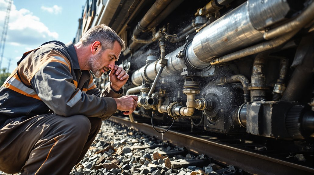
Temperature Control Requirements

Although railway diaphragm materials exhibit varying operational temperature ranges, proper storage temperature control remains critical for maintaining their structural integrity and performance characteristics. You must maintain storage temperatures at minimum +12°C to prevent elastomer degradation and preserve material flexibility. Install monitoring systems with alarm thresholds to alert when temperatures drop below specifications or exceed maximum limits for PP control blocks at 60°C.

Shield diaphragm products from direct heat sources in heated storage areas, as proximity causes premature aging. Implement thermal cycling protocols to verify material performance under temperature fluctuations. You’ll need consistent ventilation systems ensuring uniform temperature distribution throughout storage facilities. Strategic positioning away from heat sources, combined with continuous temperature monitoring, extends service life and maintains the reliability required for critical railway braking applications. Properly stored diaphragms with special elastomers continue to maintain elasticity essential for consistent braking performance in extreme conditions.

Clean Storage Areas

Maintaining sterile storage environments prevents contamination that compromises railway diaphragm performance and extends storage life up to seven years under classification C equipment standards. You’ll need clean benches and dust free zones to protect components from particulate contamination during extended storage periods. Environmental conditions must not exceed classification C specifications, requiring controlled atmospheres that maintain component integrity.

  1. Clean Benches: Install HEPA-filtered workstations for handling diaphragm components during storage preparation and inspection procedures
  2. Dust Free Zones: Establish positive pressure environments with controlled air filtration systems to prevent particulate settlement on stored parts
  3. Surface Contamination Control: Implement regular cleaning protocols using approved solvents that won’t damage protective coatings or underlying materials

Document environmental monitoring data to guarantee traceability throughout storage duration and maintain compliance with federal regulations.

Moisture Prevention Methods

Controlling moisture levels stands as the most critical factor in preventing railway diaphragm degradation during long-term storage. You’ll need to maintain optimality humidity between 50-60 percent using compressed air drying units with membrane or pressure-swing adsorption technologies. Install dew-point sensors at dryer outlets to monitor air quality and equipment efficiency continuously.

Deploy effective desiccants including silica gel sachets, calcium chloride, and specialized absorbent media within packaging. These sorption indicators provide visual confirmation of moisture absorption capacity. Implement humidity mapping throughout storage areas using rail-approved sensors meeting EN50155 and 50121-3-2 standards for outstanding accuracy.

Store diaphragms in air-tight containers to prevent circulating air exposure. Temperature differences between storage environments and ambient conditions can accelerate condensation formation on railway diaphragm surfaces. Regular monitoring with indoor humidity sensors prevents ice formation, corrosion, and material deterioration that compromises braking system integrity.

Material Handling and Movement Procedures

high capacity safe material handling

When implementing material handling and movement procedures for railway diaphragm parts, you’ll need to coordinate equipment capabilities with strict safety protocols to guarantee efficient operations. Your material handling systems can deliver up to 2,000 tons per hour with 50-foot boom reach from track center, while discharge conveyors feature positive lock mechanisms preventing inadvertent movement to live track areas. You must make certain operator ergonomics through single-technician management capabilities and camera systems providing unobstructed operational views.

Coordinating high-capacity material handling systems with stringent safety protocols ensures efficient railway operations while maintaining operator safety and operational precision.

Critical movement procedures include:

  1. Air Brake Testing Compliance – Perform Class 1 Air Brake Tests for car additions and repositioning, with specific testing required for cars off air over 4 hours
  2. Emergency Staging Protocols – Maintain pinpoint accuracy delivery systems enabling material placement up to 52 feet from track centerline with 45-degree discharge capability
  3. Safety Inspection Requirements – Verify angle cock positioning, assess air hose conditions, and conduct system leakage inspections before movement operations

Automated plow systems allow direct material unloading without tie pushing procedures. Equipment operators should maintain ergonomic positioning using air suspension seats and pilot controls to ensure safe material handling during extended work periods.

Protection From Hazardous Operations

fire and electrical safety

You must implement strict fire operation prohibitions and electrical safety protocols when storing railway diaphragm parts in maintenance environments. These protective measures become critical in ATEX-certified facilities where explosive atmospheres can develop during routine storage and handling operations. Your compliance with electrical safety standards and fire prevention protocols directly prevents catastrophic incidents that could compromise both personnel safety and stored diaphragm components. All diaphragm materials must meet EN45545 requirements as this European standard became mandatory throughout the continent in 2016 for railway vehicle components.

Prohibited Fire Operations

Although railway diaphragm parts may appear fire-resistant during normal operations, you must strictly prohibit all open flame activities, welding operations, and heat-generating processes within designated storage areas. These materials require ASTM E162 flame propagation testing and must maintain heat release rates below 140 kW/sq. m under ASTM E1354-99 standards. Any ignition source can compromise their fire performance characteristics and create catastrophic safety hazards.

Critical prohibited operations include:

  1. Open flame activities – torches, lighters, gas burners, and smoking materials that exceed safe heat flux thresholds
  2. Welding operations – arc welding, gas welding, and cutting processes generating temperatures above material safety limits
  3. Heat-generating equipment – grinding, hot work permits, and electrical equipment producing sparks near storage zones

Electrical Safety Protocols

Beyond fire prevention measures, electrical hazards pose equally severe risks to personnel handling railway diaphragm components in storage facilities. You must implement all-encompassing electrical lockout procedures before accessing any storage areas containing energized equipment. Voltage between rail sections shouldn’t exceed 25-50 volts AC to maintain worker safety thresholds.
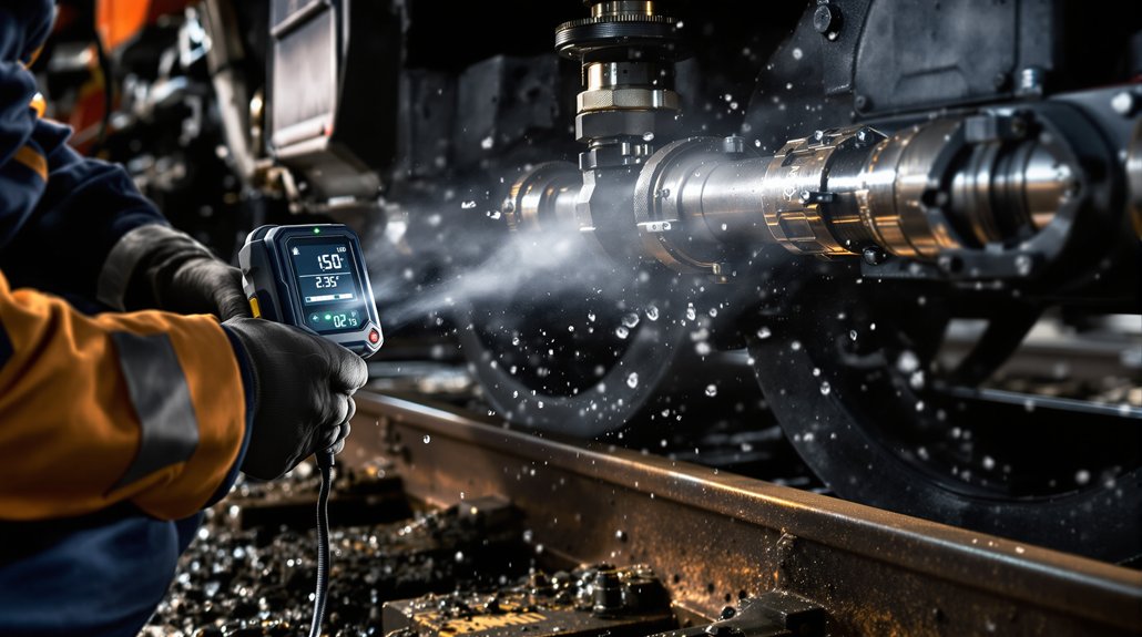
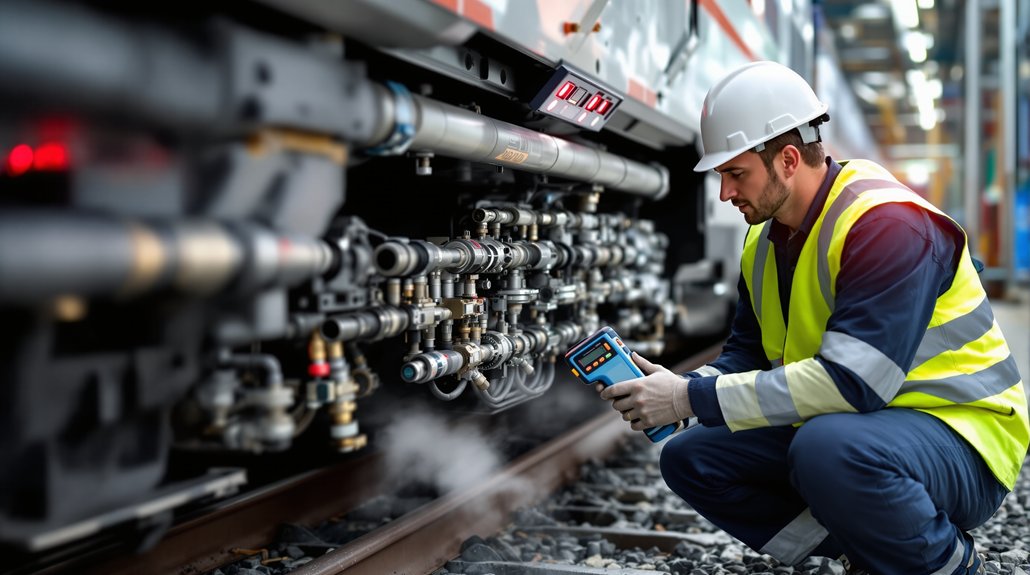
Safety ProtocolEquipment RequiredMonitoring Frequency
Live conductor identificationAugmented reality systemsContinuous
Voltage monitoringISOMETER devicesReal-time
Ground-fault detectionCircuit protection relaysAutomated
Isolation verificationClass-A grounding sticksBefore each access

Your facility needs ground-fault monitoring devices that detect cable faults quickly during operations. Install measuring relays for continuous monitoring without disconnection requirements. Confirmed operation of circuit main earths prevents inadvertent re-energization risks during diaphragm component handling. Storage areas near transmission lines require surge suppressors to protect equipment from fault-induced electrical damage.

Inventory Tracking and Rotation Systems

serialized fifo inventory tracking

Setting up effective inventory tracking and rotation systems guarantees railway diaphragm parts maintain their operational integrity while minimizing storage-related deterioration. You’ll need serialized tracking capabilities that enable individual component identification throughout the supply chain, assuring compliance with railway industry standards. Implementing automated low-stock alerts prevents critical shortages while maintaining ideal inventory levels.

Your inventory rotation protocol should follow these essential practices:

  1. First-In-First-Out (FIFO) Implementation – Track manufacturing dates and shelf life to ensure older diaphragm components are used before newer stock
  2. Real-Time Status Monitoring – Deploy automated systems that identify non-movement periods and component deterioration risks
  3. Historical Usage Analytics – Analyze consumption patterns to detect maintenance inefficiencies and optimize reorder points

Cloud-based inventory management solutions accommodate rail industry requirements while providing multi-user tracking capabilities across railroad lines. You’ll achieve thorough visibility into part movement between warehouses, enabling data-driven forecasting that supports seasonal demand adjustments and budget planning for diaphragm component procurement. Barcode data sharing with component suppliers enhances traceability and enables faster identification of affected parts during safety recalls.

Storage Layout and Space Management

systematic vertical storage management

When designing storage layouts for railway diaphragm parts, you’ll maximize operational efficiency by implementing systematic space management strategies that accommodate component dimensions, handling requirements, and accessibility needs. Configure vertical zoning systems to separate components by size and frequency of use, placing high-turnover items at accessible heights while utilizing ceiling space for slower-moving inventory.

Implement weight stacking protocols that position heavier diaphragm assemblies on lower shelving levels to maintain structural integrity and worker safety. Your mobile shelving systems should compress storage density by 50-100% through track-mounted carriages that eliminate permanent aisles. Plan strategic placement of different diaphragm categories near designated access points to reduce handling time and prevent cross-contamination.

Install space control monitoring systems that track utilization rates and alert you when areas approach capacity limits. Maintain clear aisle designations with adequate safety clearances for personnel movement and handling equipment operation, ensuring compliance with storage standards. Consider implementing vertical lift systems for efficient housing and retrieval of smaller diaphragm components that require frequent access but occupy minimal floor space.

Inspection and Quality Assurance Protocols

diaphragm inspection and documentation

Proper storage layout establishes the foundation for maintaining diaphragm component integrity, but systematic inspection protocols guarantee these parts meet stringent safety requirements throughout their service life. You’ll need to implement thorough quality assurance procedures that align with federal transportation safety regulations.

Systematic inspection protocols ensure diaphragm components meet stringent federal safety requirements throughout their operational service life.

Your daily inspections must focus on three critical assessment areas:

  1. Visual Component Analysis – Examine diaphragms for structural defects, mounting integrity, and wear plate deterioration that could compromise operational safety
  2. Documentation Compliance – Record all findings systematically, ensuring defect documentation includes component identification, location details, and corrective action requirements
  3. Technology Integration – Utilize automated inspection systems including laser scanning and optical detection devices to enhance traditional visual assessment methods

You’re responsible for maintaining inspection records that demonstrate equipment conformance to established safety standards. Qualified personnel must perform pre-departure inspections when certified inspectors aren’t available, ensuring continuous compliance with regulatory requirements and preventing equipment failures during service operations.

You may also like to read – 7 Signs Your WABCO Locomotive Brake Diaphragm Needs Replacement.

Frequently Asked Questions

What Specific Insurance Requirements Apply to Railway Diaphragm Storage Facilities?

Railway diaphragm storage facilities require $5 million minimum liability insurance coverage per occurrence, representing a 400% increase from standard warehouse requirements. You’ll need all-encompassing liability insurance including XCU coverage for explosion and collapse risks, plus specialized cargo insurance protecting stored diaphragm components. Coverage must extend to all contractors working within 50 feet of track centerline, with additional insured endorsements naming railway companies as protected parties.

How Do Seasonal Weather Changes Affect Storage Building Ventilation Requirements?

You’ll need adaptive ventilation strategies as seasons change your storage environment’s thermal dynamics. Temperature control becomes critical during summer months when you should utilize nighttime cooling to prevent heat accumulation in building mass. Moisture management requires increased mechanical backup during humid periods when natural ventilation can’t maintain proper relative humidity levels. You must adjust cross-ventilation timing and implement mixed-mode systems for consistent environmental conditions.

Which Certifications Must Storage Facility Personnel Obtain Before Handling Components?

Better safe than sorry when handling critical railway components. You’ll need thorough safety training covering proper lifting techniques, chemical handling protocols, and emergency procedures before touching any diaphragm parts. Quality certification in materials handling and storage best practices is essential. You must complete specialized training on railway component specifications, contamination prevention, and documentation requirements to guarantee compliance with industry standards and protect component integrity.

What Emergency Response Procedures Apply When Diaphragm Materials Become Contaminated?

You must immediately implement spill containment measures and establish contamination isolation zones around affected diaphragm materials. Don’t handle contaminated components without proper PPE and follow your facility’s hazmat protocols. You’ll need to notify emergency response teams, document the incident per regulatory requirements, and secure the area until decontamination specialists arrive. Always prioritize personnel safety and prevent contamination spread to adjacent storage areas.

How Should Damaged Packaging Be Disposed of According to Environmental Regulations?

Like Pandora’s box releasing unforeseen consequences, you must handle damaged packaging with strict adherence to EPA regulations. You’ll classify materials as hazardous waste if they’re contaminated with chemicals or biohazardous substances, requiring specialized disposal through licensed Treatment Storage and Disposal Facilities. Follow established recycling protocols for non-contaminated materials, converting paper, plastics, and metals into reusable components while wearing proper safety equipment throughout handling procedures.

7 Essential Railroad Air Brake Gasket Parts

7 Essential Railroad Air Brake Gasket Parts

You’ll need these seven essential gasket components for reliable railroad air brake operation: gladhand connector gaskets that seal locomotive-to-car connections, brake pipe hose assembly gaskets for system continuity, main reservoir gaskets handling high-pressure service, angle cock and cutout valve assemblies maintaining 300 PSI ratings, triple valve system gaskets controlling Westinghouse mechanisms, emergency brake sealing components for fail-safe operations, and safety control cock gaskets preventing catastrophic pressure loss. Understanding proper specifications and maintenance protocols guarantees your brake systems meet FRA safety standards.

Key Takeaways

  • Gladhand connector gaskets maintain critical pressure seals between locomotives and rolling stock with interlocking mechanisms.
  • Brake pipe hose assembly gaskets connect components throughout air brake systems at angle cock and branch pipe junctions.
  • Main reservoir system gaskets handle continuous high-pressure service using ePTFE, flexible graphite, or specialized elastomer materials.
  • Angle cock and cutout valve gasket assemblies maintain brake pipe integrity with 300 PSI operating pressure ratings.
  • Triple valve system gaskets include three sealing components: piston valve seals, slide valve gaskets, and port sealing elements.

Gladhand Connector Gaskets for Air Brake Coupling Systems

gladhand gasket maintenance tips

Railroad air brake systems depend on gladhand connector gaskets to maintain critical pressure seals between locomotives and rolling stock. You’ll find these hermaphroditic couplings use symmetric gasket implementation with interlocking mechanisms that resemble “hands shaking” when properly mated. The mating rubber grommets create positive air pressure seals that prevent external contamination from compromising brake functionality.

For effective gladhand maintenance tips, you should inspect gaskets regularly for wear, cracking, or contamination buildup. Wide lip variants (COLD LOC) enhance sealing performance in extreme conditions while maintaining elasticity from arctic to desert temperatures. When following gasket replacement procedures, you’ll need to confirm proper color-coding alignment—blue service lines and red emergency brake lines per SAE J318 standards prevent dangerous misconnections. Proper maintenance schedules should include applying silicon lube to the o-ring annually to ensure optimal sealing performance.

LOCTAB® II technology increases resistance to rotational hose uncoupling by 400% over conventional designs. You can operate these connections effectively while wearing gloves, and they provide immediate sealing without requiring tools or mechanical assistance.

Brake Pipe Hose Assembly Gaskets and Sealing Components

railroad brake hose sealing

When brake pipe hose assemblies connect various components throughout railroad air brake systems, multiple gasket and sealing points require your attention to maintain system integrity. You’ll encounter critical sealing interfaces at angle cock connections, branch pipe junctions, and hose-to-fitting termination points where M-601 and M-618 hoses meet crimped assemblies.

Your brake assembly components demand gaskets that withstand operating pressures up to 90 PSI while maintaining seal integrity during train movements and vibrations. Nitrile rubber provides reliable sealing material durability across the required -40°F to 150°F temperature range. You must guarantee gaskets resist extrusion under pressure and accommodate slight misalignment during installation. Railroad brake hose manufacturers ensure these components meet UIC-830-1-85 standard requirements for trains and locomotives to deliver consistent performance.

At 1¼ inch pipe nipple connections, you’ll need to source gaskets separately since they’re not included with standard components. Follow AAR specifications for proper dimensional compatibility and replace sealing components during routine maintenance to prevent air leakage that compromises brake system performance.

Main Reservoir System Gaskets and Pressure Seals

specialized gaskets for locomotives

Locomotive main reservoir systems operate under demanding conditions that require specialized gaskets and pressure seals designed for continuous high-pressure service and Section 229.31 compliance standards. You’ll need gaskets that withstand temperature fluctuations during compression cycles while maintaining pressure stability across dual reservoir configurations.

Material selection directly impacts gasket longevity in these challenging environments:

  1. Expanded PTFE (ePTFE) – Provides superior compressibility for conforming to flange surface imperfections and wear patterns
  2. Flexible graphite compounds – Delivers high-temperature resistance during air compression cycles with excellent vibration dampening
  3. Specialized elastomer formulations – Guarantees moisture resistance in compressed air systems while maintaining flexibility

You must follow ASME PCC-1 installation procedures for ideal compressive loading. Insufficient pressure causes leaks, while excessive compression reduces service life. Proper bolt tightening sequences ensure uniform gasket compression across equalization pipe connections. Surface preparation before installation remains critical for achieving reliable sealing performance throughout locomotive operations. Regular inspection protocols should include checking sealing surfaces for corrosion or wear to maintain system integrity.

Angle Cock and Cutout Valve Gasket Assemblies

brake pipe integrity maintenance

Critical junctions between railcars depend on angle cock and cutout valve gasket assemblies to maintain brake pipe integrity throughout train consists. You’ll find these critical components positioned at each car’s brake pipe ends, where they enable secure hose connections and system closure capabilities.

During angle cock maintenance, you must install service portion pipe bracket gaskets before attaching service portions. Tighten three 5/8″ hex nuts to precisely 65-75 ft-lbs torque specifications using graduated steps to prevent gasket distortion. Never overtighten, as this damages covers and creates leakage paths.

For cutout valve functionality, Type AAR M-618 connections with crimped fittings maintain 300 PSI operating pressure ratings. Standard size designations (-10 through -24) correspond to different pipe dimensions and weight specifications.

You’ll need DB-60 Installation Drawings 782222 or 782241 for proper configuration. Always perform air brake testing before replacement begins and verify no air leakage at gasket interfaces post-installation.

Triple Valve System Gaskets for Westinghouse Controls

triple valve gasket maintenance

You’ll find three critical sealing components within Westinghouse triple valve assemblies that require precise maintenance attention. Your piston valve sealing components create air-tight barriers between the reservoir, brake cylinder, and train-pipe circuits, while slide valve gaskets enable smooth shifts between service and emergency positions. You must inspect graduating valve seal requirements regularly, as these components directly control pressure equalization rates that determine your train’s braking response characteristics. Poor gasket maintenance can lead to air loss from unsuitable packing materials, which disrupts pump efficiency and overall brake system performance.

Piston Valve Sealing Components

Precision-engineered sealing components within the piston valve assembly control critical air flow pathways between your train-pipe, auxiliary reservoir, and brake-cylinder compartments in Westinghouse triple valve systems. These seals maintain separation through opening C connections while enabling controlled charging cycles through grooves d and f. Proper piston valve maintenance guarantees fail-safe operation during uncommanded pressure losses, triggering automatic brake applications.

Your WF4 triple valve’s sealing component materials must withstand:

  1. Rapid pressure changes during service reductions without compromising seal integrity
  2. High-fidelity operational cycles while maintaining proper “lap off” positioning when pressures equalize
  3. Manufacturing tolerance variations that affect brake signal propagation speed along train consists

These components prevent premature air equalization, guaranteeing reliable brake-cylinder exhaust port closure during controlled braking operations throughout your entire train length. Modern distributors provide enhanced control capabilities with partial brake release functionality for improved operational precision.

Slide Valve Gasket Applications

Beyond the piston valve sealing requirements, your triple valve’s slide valve gaskets maintain the pressure differentials that control brake application sequencing throughout Westinghouse air brake systems. Rubber gasket #9356 creates reliable port sealing between the valve body and mounting bracket, while gasket #131A secures the cylinder cap interface. Your slide valve wraps around the piston stem assembly with leaf spring force maintaining proper positioning against mating surfaces.

The slide valve requires greater pressure differentials to move compared to graduating valves, with increased friction deliberately engineered for proper sequencing. During gasket maintenance, you’ll need to match original equipment specifications and follow proper bolt torque sequences. Visual inspection detects gasket degradation, and specialized tools may be required for accessing internal components during triple valve overhauls.

The Westinghouse M2A triple valve incorporates graduated release capabilities that enhance braking control precision during service applications.

Graduating Valve Seal Requirements

Critical sealing integrity within your Type L Triple Valve’s graduating valve assembly depends on component #7’s precise interaction with the graduating sleeve and spring mechanisms. Your nitrile rubber seals must maintain 70-80 durometer hardness specifications while withstanding continuous 90 PSI operations across -40°F to 140°F temperature ranges.

Seal durability requirements include:

  1. Material resistance – Petroleum-resistant Buna-N formulations prevent degradation from compressed air moisture exposure
  2. Pressure resilience – Seals withstand emergency application surges without distortion or leakage between service chambers
  3. Compression integrity – Proper elasticity maintenance prevents lap-off during reservoir-to-cylinder air transfer cycles

The distributing valve’s equalising portion works in conjunction with the pressure chamber to regulate proper seal engagement during brake applications. You’ll need replacement every 3-5 years regardless of visual condition. Monitor for seal hardening, compression set, and cracking during quarterly inspections to prevent incomplete valve closure and inconsistent brake applications.

Emergency Brake System Sealing Components

emergency brake sealing integrity

When you’re maintaining emergency brake systems, you’ll encounter three critical sealing categories that demand immediate attention during any pressure loss event. Your safety control cock gaskets must seal instantly to isolate brake pipe sections, while emergency valve sealing systems require precision-machined surfaces that activate within milliseconds of pressure reduction. You’ll also need to verify that rapid pressure transfer components maintain their seal integrity under extreme pressure differentials, as any failure triggers automatic emergency applications throughout the entire train consist. During emergency applications, the system combines air from both auxiliary and emergency reservoirs to deliver maximum braking force when brake pipe pressure drops rapidly to zero.

Safety Control Cock Gaskets

Safety control cock gaskets serve as the primary sealing barriers that prevent catastrophic air loss during emergency brake interventions across freight, passenger, and locomotive operations. You’ll find these critical components engineered with temperature-resistant compounds that maintain flexibility during extreme weather conditions while withstanding 150psi operational pressures. The gasket durability directly impacts your system’s reliability through abrasion-resistant polymers that resist brake pipe contaminants.

Essential safety features include:

  1. Cut-out cock isolation – Separates control valve communication during emergency procedures
  2. Vent valve integrity – Maintains seal during locomotive contamination events
  3. Retaining valve regulation – Controls brake cylinder exhaust across operational positions

Modern gasket assemblies incorporate centrifugal dirt collector technology that enhances air system integrity by removing contamination before it reaches critical sealing surfaces. You must ascertain FRA §230.75 compliance through proper stenciled test documentation and follow §230.78 leakage prevention criteria during inspections.

Emergency Valve Sealing Systems

Although emergency valve sealing systems represent the railroad industry’s most critical fail-safe technology, they’ll only perform effectively when their specialized sealing components maintain absolute integrity under extreme operational pressures. Your emergency valve design must incorporate high-precision components manufactured within narrow dimensional tolerances to guarantee reliable performance. These systems activate when brake pipe pressure drops, triggering immediate emergency applications across every car simultaneously.

You’ll need sealing surface materials engineered specifically for rapid pressure changes exceeding 15 psi per second. Emergency reservoirs, triple valve interfaces, and control valve pistons all require specialized sealing compounds that withstand extreme temperature variations. Your emergency brake cylinders must utilize high-performance seals that transfer maximum air pressure instantly, creating ideal friction between brake shoes and wheels during critical stopping situations.

The sealing compounds must incorporate fiber-reinforced structures to prevent component fractures during extreme temperature fluctuations and high-stress emergency braking events.

Rapid Pressure Transfer Components

Milliseconds determine whether your emergency brake system delivers life-saving stopping power or catastrophic failure during critical rail operations. Your rapid pressure transfer components must handle extreme pressure variations while maintaining absolute seal integrity throughout emergency applications.

Critical Performance Requirements:

  1. Pneumatic hose durability – Multi-layer construction withstands 125-140 psi continuous pressure plus sudden surges, operating reliably from -40°F to 250°F
  2. Pressure surge management – Equalizing reservoir interfaces maintain 90-110 psi equilibrium with precision-machined flanges preventing leakage during critical equalization phases
  3. System integrity – Main reservoir connections use spiral-wound gaskets meeting ASME B1.20.1 standards, tested to 150% operating pressure without failure

You’ll need specialized gasket materials with dimensional tolerances within 0.002 inch to prevent pressure equalization timing errors that compromise emergency braking effectiveness.

Safety Control Cock and Feed Valve Gaskets

brake gasket maintenance essentials

When you’re maintaining railroad air brake systems, safety control cock and feed valve gaskets serve as critical sealing components that prevent brake pipe pressure loss and guarantee proper penalty feature activation during emergency scenarios. These AAR-compliant rubber compound gaskets integrate with centrifugal dirt collectors to prevent contamination ingress while maintaining low-torque operation under vibration stress.

Modern feed valve gaskets utilize high-strength noncorrosive plastic composition, delivering 40% weight reduction while withstanding -40°F to 150°F operational environments. Your gasket durability analysis should focus on chemical resistance to oil and moisture contaminants, as failures contribute to 12% of brake hose coupling deficiencies.

During sealing integrity assessment, you’ll conduct mandatory bi-annual replacements per FRA regulations and visual inspections at 92-day intervals. Failed gaskets cause brake pipe pressure leakage exceeding 5 psi/min thresholds and trigger automatic brake release failures. AAR Specification S-40 governs dimensional tolerances across all locomotive brake applications.

You may also like to read – Why Replace Pneumatic Control Valve Gaskets in Locomotives?

Frequently Asked Questions

How Often Should Railroad Air Brake Gaskets Be Inspected and Replaced?

You should inspect railroad air brake gaskets every 368 days following standard gasket maintenance frequency protocols. Replace gaskets during each inspection cycle or immediately when you detect wear, deterioration, or damage. Your inspection protocols must include systematic checks of all connections, particularly around compressors where leaks commonly occur. Document all maintenance activities for regulatory compliance and align replacement schedules with manufacturer specifications for optimal safety performance.

What Are the Signs of Gasket Failure in Air Brake Systems?

You’ll recognize gasket failure through constant compressor cycling, audible hissing at connections, and pressure build-up exceeding two minutes from 80-100 psi. Watch for brittle, cracked gaskets showing visible hardening or shrinking. Monitor for excessive moisture drainage, inconsistent braking performance, and leakage test results surpassing 5 psi per minute. These failure indicators demand immediate gasket maintenance to prevent system compromise and guarantee operational safety.

Can Different Gasket Materials Be Substituted in Emergency Situations?

You shouldn’t substitute different gasket materials in emergency situations due to strict gasket compatibility requirements under AAR specifications. Emergency replacements must meet identical material standards and dimensional specifications as original equipment. Substituting incompatible materials can cause seal failure, air leaks, and brake system malfunctions. You’ll violate AAR S-400 and S-401 standards while compromising safety. Always use approved, application-specific gaskets that meet or exceed OEM specifications for reliable brake system operation.

What Tools Are Required for Proper Gasket Installation and Removal?

Don’t assume basic hand tools will suffice for railroad brake work. You’ll need specialized gasket installation equipment including the Lokring MTK50-RR toolkit with hydraulic Loktool heads for proper fitting connections. For gasket removal, use dedicated extraction tools and Glad Hand 2-in-1 service tools. Essential components include electric pump kit 9080184, calibrated torque tools, and air brake testing devices for post-installation verification and safety compliance.

How Do Temperature Extremes Affect Gasket Performance and Longevity?

Temperature extremes severely compromise gasket durability by reducing elasticity and sealing effectiveness below -25°C. You’ll experience exponential air leakage increases as rubber materials harden and shrink in extreme cold. Your brake system’s temperature resilience diminishes considerably, causing pressure loss within three hours of stationary application. You must implement accelerated replacement schedules and temperature-adjusted maintenance protocols to maintain safe braking performance in cold climates.

Why Replace Pneumatic Control Valve Gaskets in Locomotives?

Why Replace Pneumatic Control Valve Gaskets in Locomotives?

You must replace pneumatic control valve gaskets to prevent catastrophic brake failures that can create deadly runaway conditions. Deteriorated gaskets cause air leakage pathways, compromising brake system integrity and extending stopping distances dangerously. Failed gaskets prevent proper emergency brake activation, reduce critical pressure differentials below the required 10-15 psi, and undermine fail-safe braking architecture. Following manufacturer protocols for gasket replacement every 24 months guarantees your locomotive’s safety systems remain reliable when you need them most.

Key Takeaways

  • Gasket failures create air leakage pathways that compromise braking system integrity and can lead to extended stopping distances.
  • Deteriorated gaskets prevent proper emergency brake activation, potentially causing runaway conditions on descending grades and system failures.
  • Regular gasket replacement every 24 months maintains critical pressure differentials and ensures reliable brake response within 1-2 seconds.
  • Intact gaskets are essential for emergency braking systems to transfer full 70 psi pressure to brake cylinders effectively.
  • Timely gasket maintenance reduces unplanned downtime by 42% and prevents costly brake application failures during critical operations.

Air Leakage Prevention Through Proper Gasket Sealing

effective gasket sealing solutions

Preventing air leakage in locomotive pneumatic control systems depends entirely on achieving proper gasket compression and material compatibility with your specific valve housing configurations. Advanced gasket materials featuring controlled swell technology expand when contacting sealing media, automatically filling voids and imperfections on flange surfaces. This precision-enhanced molecular structure adapts to surface irregularities that conventional materials can’t accommodate.

You’ll need proper bolt torque application to create sufficient compression for complete sealing surface engagement. Multi-layer composition prevents air permeation through microscopic channels while maintaining crush resistance under operational pressure fluctuations. The sealing technology incorporates elastic recovery properties that maintain integrity during pressure cycling common in locomotive systems.

Inadequate sealing performance reduces system pressure efficiency by up to 15% and forces compressors to cycle more frequently, increasing energy consumption by 20-30%. Temperature stability from -40°F to 300°F guarantees consistent performance across operational thermal ranges. Quality AAR M-1003 certified gasket materials undergo thorough analysis and testing processes to ensure reliable performance in demanding rail applications.

Safety Implications of Gasket Failure in Brake Systems

gasket failure impacts braking safety

When gasket failures compromise your locomotive’s brake systems, you’re facing three critical safety scenarios that can escalate rapidly into catastrophic incidents. Brake application failures from degraded gaskets can prevent your train from stopping effectively, while complete gasket deterioration creates runaway conditions that put your entire consist at risk on descending grades. You must understand that compromised gaskets don’t just reduce braking power—they can trigger emergency system failures that leave you without reliable control when you need it most. The fail-safe design of modern air brake systems means any loss of air pressure from gasket failure automatically applies brakes, but degraded seals can prevent proper pressure maintenance needed for controlled operations.

Brake Application Failures

Compromised pneumatic control valve gaskets create cascading failures throughout locomotive brake systems that directly threaten operational safety. When your gaskets deteriorate, you’ll experience reduced brake pressure that prevents achieving the required 26 psi service reduction. This degraded pneumatic efficiency causes delayed brake application timing, creating dangerous scenarios during grade descents where insufficient braking force can’t control train movement.

You’ll notice inconsistent pressure differentials that cause variable brake shoe engagement timing, particularly problematic in Very Long Train operations. Compromised auxiliary reservoir charging between applications leads to unintended brake releases during subsequent operations. These failures compound as multiple small leaks throughout your pneumatic system create significant performance degradation. The gradual nature of gasket deterioration often masks these critical safety issues until catastrophic brake system failure occurs.

Modern ECP brake technology provides superior control and shorter stopping distances compared to conventional air brake systems, addressing many of the safety vulnerabilities created by gasket failures in pneumatic control valves.

Runaway Train Risks

As air leakage rates exceed critical thresholds, your locomotive’s brake system enters a dangerous failure cascade that can trigger runaway train conditions. When pneumatic sealing fails at gasket interfaces, you’ll face progressive brake release starting with trailing cars. At 21 psi/min leakage, the last six cars of a 52-vehicle train lose braking capability entirely.

Leakage RateCars AffectedSafety Status
5 psi/minNoneSafe Operation
21 psi/minLast 6 carsCritical Risk
23 psi/minLast 14 carsRunaway Likely
60+ SCFMMajor sectionsImmediate Danger
Isolated sectionEntire segmentComplete failure

Historical precedents demonstrate how compromised pneumatic sealing creates isolated brake pipe sections, eliminating speed control on descending grades. Effective runaway prevention requires maintaining gasket integrity before exceeding these documented failure thresholds. Control valve problems can prevent proper brake application and release, compounding the safety risks during emergency applications when immediate stopping power becomes critical.

Emergency System Compromise

Beyond the immediate risks of runaway conditions, gasket deterioration fundamentally undermines your locomotive’s fail-safe emergency braking architecture. When gaskets partially fail, they create undetected vulnerabilities that compromise emergency signaling throughout your train consist. Single-ended angle cock closures from deteriorated seals produce asymmetric pressure distribution, preventing uniform emergency brake activation across all cars.

You’ll face critical delays when compromised gaskets restrict brake pipe pressure propagation during emergency applications. The standard 5-bar brake pipe pressure can’t reach all train sections effectively when gasket deterioration creates partial flow restrictions. Cold weather exacerbates these failures, with temperatures below -25°C considerably reducing seal effectiveness. Your emergency response becomes unreliable when differential brake responses occur across train sections, creating dangerous stopping inconsistencies.

Gasket deterioration directly contributes to brake cylinder air leakage, with approximately 50% of cars experiencing reduced air brake effectiveness during critical descent operations.

Pressure Regulation Mechanisms and Gasket Integrity

You must understand how gasket integrity directly affects your locomotive’s pressure regulation mechanisms to maintain proper brake system operation. When you’re working with pneumatic control valves, chamber separation requirements depend on high-quality gaskets that prevent pressure equalization between functional compartments. Your relay valve’s ability to balance delivery pressure and control brake cylinder response relies on these critical sealing components maintaining hermetic barriers during dynamic pressure changes. The gaskets must prevent air leaks to ensure system efficiency, as pressure drops can create energy inefficiencies that compromise your locomotive’s overall braking performance.

Chamber Separation Requirements

When pneumatic control valves fail to maintain proper chamber separation, you’ll face cascading system failures that compromise locomotive safety and operational efficiency. Effective chamber isolation depends on gaskets creating distinct pressure zones that prevent cross-contamination of control signals.

ComponentSpecificationCritical Impact
Surface Flatness0.002″ max deviationEliminates leakage pathways
Pressure Tolerance±5 psi differentialGuarantees proper valve sequencing
Gasket Thickness±0.005″ toleranceMaintains chamber separation
Torque Application25-35 ft-lbsAchieves ideal compression

You must guarantee gaskets compress uniformly between mating surfaces to fill surface imperfections. Without proper chamber isolation, pressure equalization occurs between zones, causing delayed brake response and triggering false monitoring system alerts that increase maintenance costs. Regular gasket replacement intervals based on manufacturer specifications prevent premature seal degradation and ensure consistent chamber separation performance.

Relay Valve Balance

After achieving proper chamber separation, relay valve balance becomes the critical mechanism that determines whether your locomotive’s pneumatic control system maintains precise pressure regulation. Your relay valve functionality depends on maintaining equilibrium through exact pressure differentials across diaphragm assemblies. When service line pressure equals delivery pressure, both inlet and exhaust valves close, creating the balanced position essential for safe operations.

You’ll need to monitor pressure differential dynamics carefully, as standard R12 relay valves require 4 PSI nominal crack pressure within ±1 PSI tolerance. Compromised gaskets disrupt this delicate equilibrium by allowing pressure leakage between chambers. Failed seals prevent proper lapping off, causing unintended brake applications and inconsistent performance across your train consist. The relay valve operates through a relay piston that responds to control air pressure changes from the foot valve. Preserving gasket integrity guarantees your diaphragm assemblies can sense subtle pressure changes necessary for precision control.

Delivery Pressure Control

Because delivery pressure control forms the backbone of locomotive braking safety, your pneumatic system’s pressure regulation mechanisms must maintain exact delivery pressures through complete gasket integrity across all valve assemblies. Compromised seals create pressure fluctuations that directly undermine braking reliability and operational safety.

When gasket materials degrade, you’ll experience:

  • Continuous pressure restoration attempts by relay valves due to cylinder leakage
  • Inconsistent delivery pressure from unintended air flow through failed seals
  • Erratic brake application and release behaviors from pressure instability
  • Increased compressor cycling frequency indicating system-wide leakage
  • Inadequate brake cylinder pressure during critical operational moments

Regular pressure testing identifies seal failures before they undermine system performance. Proper gasket replacement using manufacturer-specified materials guarantees dimensional matching and pressure-rated integrity across operational ranges. Pressure control valves incorporate safety mechanisms to prevent over-pressurization and potential damage, which is why maintaining gasket integrity becomes even more critical for these protective systems.

How Degraded Gaskets Contribute to Runaway Conditions

gasket degradation causes runaway conditions

As pneumatic control valve gaskets deteriorate beyond acceptable tolerances, they create critical air leakage pathways that directly compromise your locomotive’s braking system integrity. These gasket deterioration effects manifest as continuous air escape from both service and emergency brake chambers, preventing proper pressurization during critical scenarios.

You’ll experience progressive pneumatic system vulnerabilities as brittle gasket material fails to maintain minimum pressure thresholds. Your air compressor works overtime attempting to compensate for chronic leaks, while pressure depletion accelerates across multiple train car systems. This cascading failure prevents effective brake cylinder engagement and compromises kinetic energy management on descending grades.

When emergency braking activation fails due to insufficient chamber pressurization, you’re facing extended stopping distances and delayed response times. Complete gasket degradation eliminates your ability to control train speed or execute emergency procedures, creating uncontrolled acceleration scenarios that can trigger catastrophic runaway conditions without functional brake intervention. Degraded gaskets also cause unstable valve action due to fluctuating air supply pressure throughout the pneumatic control system.

Manufacturer Maintenance Protocol Requirements for Gasket Replacement

strict gasket replacement protocols

Locomotive manufacturers establish stringent maintenance protocols that mandate specific gasket replacement intervals to prevent the catastrophic brake failures described above. You must follow calendar-based replacement schedules rather than condition-based approaches for critical pneumatic control valves.

Your maintenance scheduling requires these essential protocols:

  • Replace all rubber components including valve head gaskets every 24 months regardless of apparent condition
  • Specify exact gasket material composition (nitrile, EPDM) based on pneumatic control valve locations per manufacturer documentation
  • Complete mandatory Periodic Overhaul (POH) procedures with total valve dismantling and gasket replacement
  • Apply W.H.B. grease to both sides during triple valve gasket installations with precise specifications
  • Send defective triple valves to authorized workshops rather than attempting field repairs

You’ll find that O-rings and K-rings must be replaced after exactly two years of service. Pilot devices like B-3-B valves utilize specialized gasket compounds resistant to constant air exposure and pressure cycling, ensuring operational safety.

Identifying Failure Indicators and System Symptoms

pneumatic valve gasket failure indicators

Early detection of pneumatic control valve gasket failures prevents catastrophic brake system malfunctions that endanger both crew safety and operational integrity. You’ll recognize gasket wear through specific indicators requiring immediate attention. Listen for hissing sounds at valve housing connections and monitor pressure drops exceeding 10% during operational cycles. Apply leak detection solution to gasket joints—visible bubble formation confirms compromise.

Watch for erratic valve movement patterns and extended cycle times exceeding manufacturer specifications by 25%. Complete valve stiction events demanding manual intervention signal advanced deterioration. Examine gaskets for brittle, hardened material showing elasticity loss and asymmetric wear patterns indicating misalignment.

Contamination evidence includes lacquer deposits on piston rings, oily substances in feed valves, and carbon accumulations on internal components. Pressure system anomalies manifest as fluctuations exceeding ±15 psi during stable conditions and inability to maintain set pressure points. Effective leakage detection protocols enable proactive gasket replacement before system failure compromises locomotive operations.

Critical Role of Gaskets in Emergency Brake Application

gasket integrity ensures emergency braking

When emergency brake applications occur, gasket integrity becomes the critical factor determining whether your locomotive’s braking system responds within the life-saving 1-2 second window required for safe operations. Compromised gaskets prevent triple valves from detecting the rapid 5 psi per second pressure drop necessary for emergency response activation.

Failed gasket seals can delay emergency brake response beyond the critical 1-2 second safety window, potentially causing catastrophic locomotive accidents.

Gasket efficacy directly impacts these critical emergency brake functions:

  • Pressure differential maintenance – Intact seals preserve the 10-15 psi differential between brake pipe and auxiliary reservoir required for triple valve emergency positioning
  • Signal propagation – Air-tight gaskets enable emergency pressure waves to reach rear cars within 5 seconds, preventing dangerous 8-second delays
  • Force application – Proper sealing guarantees complete 70 psi auxiliary reservoir pressure transfers to brake cylinders for maximum braking force
  • System synchronization – Failed gaskets disrupt sequential emergency application beyond the initial 20-30 cars in long consists
  • Response verification – Intact seals produce consistent venting sounds confirming complete emergency application

Preventing System Pressure Loss Through Gasket Maintenance

gasket maintenance ensures pressure stability

Beyond emergency response scenarios, maintaining gasket integrity forms the backbone of your locomotive’s overall pneumatic system efficiency. You’ll prevent 15-20% system pressure degradation by replacing aging rubber compounds before they lose elasticity within standard maintenance intervals.

Your systematic approach should target essential failure points where micro-cracks develop from constant pressure cycling between 90-140 PSI. Temperature fluctuations from -40°F to 140°F create dimensional changes that compromise seal integrity, while contaminant particulates accelerate erosion through abrasive wear patterns.

You’ll achieve ideal gasket longevity by following the mandatory 18,000-22,000 operating hour replacement cycle. Proper maintenance reduces unplanned downtime by 42% and decreases air compressor cycling frequency by 25%. Your air quality management becomes vital—moisture above 7 ppm and oil contamination exceeding 5 mg/m³ greatly accelerate rubber degradation, requiring more frequent interventions to maintain system pressure stability.

Frequently Asked Questions

What Is the Typical Lifespan of Pneumatic Control Valve Gaskets?

Your gaskets gracefully retire after eight years under industry standards, though gasket degradation factors like temperature fluctuations and moisture exposure can shorten this timeline. You’ll notice elasticity loss and brittleness developing progressively during service. Following maintenance schedule tips means you shouldn’t wait for reactive replacements—proactive eight-year intervals prevent brake system failures. Extended use beyond designed lifespan compromises your emergency braking capability and creates safety hazards.

How Much Does Gasket Replacement Cost Compared to System Failure Repairs?

You’ll spend considerably less on gasket replacement than system failure repairs. Simple gasket servicing costs under $200 with thirty minutes labor when parts are available, while system failures generate substantial operational revenue losses during service interruptions. Following proper maintenance schedules prevents gasket wear from exceeding 0.015-inch thresholds. Coastal operations require 500-hour inspections, but preventive gasket replacement dramatically reduces expensive emergency repairs and carrier testing delays.

Can Different Gasket Materials Improve Performance in Extreme Weather Conditions?

Like armor against nature’s assault, advanced gasket materials greatly enhance your locomotive’s performance in extreme conditions. You’ll achieve superior gasket durability by selecting silicone for Arctic operations down to -75°F, or graphite composites for desert heat exceeding 900°F. Weather resistance improves markedly when you match material properties to environmental demands—EPDM for sub-zero flexibility, Viton for chemical exposure, ensuring reliable pneumatic control valve operation year-round.

Which Tools Are Required for Proper Gasket Installation and Removal?

You’ll need specialized Harbor Freight HW0107 valve seal pliers and carbide-tipped scrapers for gasket removal without damaging flange surfaces. Your installation tools must include calibrated torque wrenches, alignment pins for proper C-Swell PS-2™ positioning, and hydraulic pressing equipment applying 500-1000 PSI compression. Don’t forget surface preparation equipment like flange analyzers verifying 0.002″ tolerance and industrial cleaning solvents ensuring contamination-free surfaces for ideal seal integrity.

How Often Should Gasket Inspections Be Performed During Routine Maintenance?

After Norfolk Southern discovered deteriorated gaskets during a routine 92-day inspection that prevented costly brake system failures, you should follow established gasket inspection frequency protocols. Conduct gasket inspections every 368 days per regulatory mandates, with additional checks during annual §229.27 tests. Your routine maintenance guidelines must include immediate gasket evaluation when detecting air leaks, pressure anomalies, or following any valve reconditioning to guarantee peak pneumatic system performance.

Translate »