

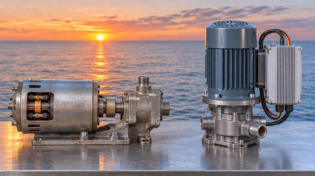
Soak-back pumps on EMD-type diesel locomotives have been driven by two very different kinds of motor. Older installations use a brushed DC motor that runs straight off the locomotive’s battery. Newer designs use an AC motor fed by an inverter, often in a compact vertical layout. Both do the same job: they move oil to the turbocharger bearings when the engine-driven lube pump is not doing so.
The two systems differ in how they draw power and how they respond as battery voltage changes. They also differ in what they need over a long service life. These differences matter when you are maintaining a mixed fleet, planning an upgrade or checking whether a replacement unit will suit a particular locomotive.
This guide explains how each system is designed, how the inverter-driven vertical type works, and what to consider when matching a soak-back setup to a 567, 645 or 710 engine. Configurations vary between engine models, build years and later modifications. Always check the wiring diagrams and maintenance manual for your locomotive before changing any part of the system.
What a Soak-Back Drive System Has to Do
The duty cycle: pre-lube and post-shutdown running
The engine’s main lube oil pump is driven by the engine itself, so it only delivers oil while the crankshaft is turning. The soak-back pump covers the periods when the main pump cannot.
Before starting: on systems configured for pre-lubrication, the soak-back pump supplies oil to the turbocharger bearings before the engine cranks. This avoids dry running during the first moments of rotation.
After shutdown: the pump keeps running for a timed period while the turbocharger cools. Depending on the locomotive’s configuration, it may also run while the engine is operating.
This duty cycle places specific demands on the motor:
- It must start reliably on demand, often after the locomotive has stood idle for hours or days.
- It must run for an extended period on battery power alone, after the charging system has stopped.
- It must do all this in a hot, oily, vibrating environment.
Power source: the locomotive’s low-voltage DC system
Auxiliary equipment on EMD-type locomotives runs from a low-voltage DC system, typically 74 VDC nominal. While the engine runs, the charging system supports this voltage. Once the engine stops, the batteries supply everything on their own.
That makes the supply far from steady:
- During cranking: voltage drops sharply as the starter draws heavy current.
- After shutdown: voltage falls gradually as the batteries discharge.
- With the charging system working: voltage sits above the nominal figure.
- With worn or weak batteries: voltage sits well below it.
Equipment designed for this environment is commonly specified to accept a wide input window, often in the region of 40 to 90 VDC. Any soak-back motor, whatever its type, has to tolerate this range and keep working across it.
Why the motor choice matters
Soak-back pumps are positive-displacement pumps, so the oil they deliver is roughly proportional to the speed they turn. Anything that changes motor speed changes the amount of oil reaching the turbocharger.
This links the motor’s electrical behaviour directly to bearing protection. The post-shutdown period is when the turbocharger most needs oil, and it is also when the motor runs on batteries alone and voltage is falling. How the motor responds to that voltage drop is the most important technical difference between the DC and AC designs.
The motor type also affects maintenance workload, the skills a depot needs, and the number of parts that can wear out or fail. These factors weigh as heavily as performance when choosing between the two systems.
The Traditional DC Soak-Back Motor
How a brushed DC motor works
A brushed DC motor has two main electrical parts:
- Field coils: windings mounted in the motor frame that create a magnetic field when current flows through them.
- Armature: the rotating part, carrying its own windings on the motor shaft.
The armature windings connect to a commutator, a ring of copper segments on the shaft. Carbon brushes press against the commutator and feed current into the armature. As the shaft turns, the commutator switches the direction of current in each winding at the right moment, keeping the motor turning in one direction.
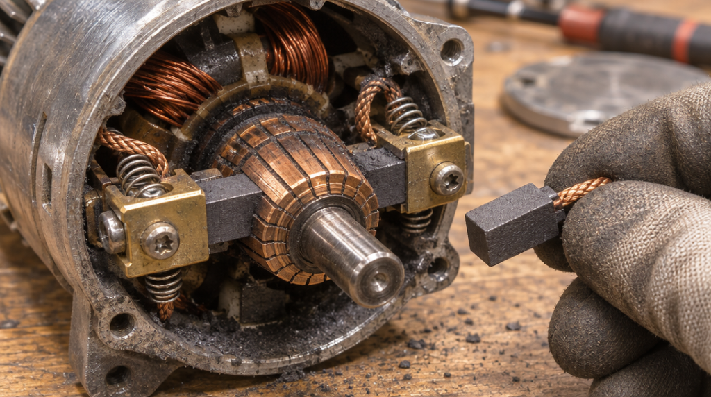
In a soak-back installation, the motor is wired to the battery supply through a circuit breaker and a contactor. The control circuit closes the contactor to start the pump and opens it when the timer expires. There is no power conversion between the battery and the motor.
Strengths of the DC design
The DC design has served locomotive fleets for decades, with clear advantages:
- Simplicity: the power path runs from battery to breaker to contactor to motor, with nothing in between that needs configuring.
- Starting torque: brushed DC motors can produce strong torque from standstill, which helps when starting a pump against cold, thick oil.
- No electronics: with no power semiconductors, nothing is exposed to the heat and vibration damage that can affect electronic equipment.
- Familiarity: most depots understand DC motors well, and the motors can usually be repaired by rewinding the armature, resurfacing the commutator or replacing brushes.
For a fleet running original configurations with established DC maintenance practices, these are strong reasons to stay with the design.
Limitations: brushes, commutator wear and voltage-dependent speed
The weaknesses of the DC design come from the same parts that make it work.
Wear parts:
- Brushes wear with every hour of running and need regular inspection and replacement.
- The commutator wears as well, and can develop grooving or burning over time.
- Brush wear produces carbon dust inside the motor, which can track across insulation.
- Arcing at the brushes increases as parts wear.
Running hours: post-shutdown running periods add up quickly. A locomotive that shuts down several times a day accumulates significant motor hours even when it is not working hard.
Voltage-dependent speed: a brushed DC motor’s speed depends partly on the voltage applied to it. As the batteries discharge after shutdown, the motor slows to some degree, and pump delivery falls with it. The size of the effect depends on the motor’s winding design and load, but the direction is the same. The batteries fall furthest when the turbocharger most needs oil.
Cold-oil current: cold, thick oil increases the load at starting, which raises current draw and puts further stress on the brushes and commutator.
How the Inverter-Driven Vertical AC Type Works
The inverter: turning battery DC into motor AC
An inverter converts the locomotive’s DC supply into alternating current to drive an AC motor. Inside, power semiconductors switch the DC input on and off in a controlled sequence to build an alternating output. In soak-back applications, the output is often a quasi-sine wave (sometimes called a modified sine wave) rather than a pure sine wave. The output frequency is typically in the 50 to 60 Hz range.
The key design point is that the inverter’s electronics set the output frequency, not the battery voltage. As long as the DC input stays within the inverter’s accepted window, the output frequency stays essentially constant. On some designs, the AC output voltage is lower than the DC supply, for example around 55 VAC, with the motor wound to suit.
Inverters for this duty commonly include protective functions such as:
- Under-voltage cut-off: shuts down before the batteries are drained too far.
- Over-voltage protection: guards against charging-system spikes.
- Over-current and short-circuit protection: protects the motor and wiring.
- Thermal protection: shuts down if the inverter overheats.
- Soft start: ramps up gradually to limit current at switch-on.
Depending on the design, the inverter may be mounted separately from the pump or built into the motor assembly.
The AC induction motor: brushless and speed-stable
The motor itself is usually an AC induction motor, which has a much simpler construction than a brushed DC machine.
AC current in the stator windings creates a rotating magnetic field. This field induces current in the rotor, typically a cage of conductive bars with no external electrical connections. The induced current produces torque, and the rotor follows the rotating field. There are no brushes and no commutator.
The speed of an induction motor depends mainly on the supply frequency and the number of magnetic poles in its winding. It runs slightly slower than the rotating field, a difference called slip, which changes only modestly with load. Since the inverter holds the frequency steady, the motor speed stays steady too. Pump delivery therefore stays more consistent across the battery’s discharge cycle than with a brushed DC motor.
With no brushes, routine motor maintenance is reduced mainly to the bearings. There is no carbon dust, no commutator wear and no brush arcing.
What “vertical type” means in practice
“Vertical type” generally describes the physical layout of the assembly. The motor stands upright on top of the pump, with its shaft vertical, instead of sitting horizontally alongside the pump on a common bracket.
This arrangement can offer several practical benefits:
- A compact footprint in a crowded engine compartment
- A short, direct coupling between motor and pump
- A motor positioned above the oil-handling parts
The term is not used identically everywhere, however. Before treating any two vertical-type units as interchangeable, check these against the installation drawing for your locomotive:
- Mounting faces and bolt pattern
- Inlet and outlet port positions
- Overall height and clearance envelope
- Electrical connection point
The inverter-driven design also brings trade-offs:
- More parts: the system adds a power-conversion stage, so there are more components in the power path than with a direct DC motor.
- Heat sensitivity: the electronics need suitable mounting and enough cooling, because engine compartments run hot.
- Different repair skills: fault-finding moves from mechanical brush and commutator work to electronic module testing, which many depots handle by replacing the inverter as a unit.
Matching the System to 567, 645 and 710 Engines
Which engines need a soak-back system
A soak-back system exists to protect the turbocharger, so the first question is whether the engine has one. The three EMD engine families differ here:
- 567 series: most were Roots-blown. Turbocharged versions appeared in the late 1950s and early 1960s.
- 645 series: built in both Roots-blown and turbocharged forms.
- 710 series: locomotive versions are turbocharged.
A Roots-blown engine has no turbocharger bearings to protect after shutdown, so it does not need a turbocharger soak-back system. On turbocharged 567, 645 and 710 engines, a working soak-back system is essential.
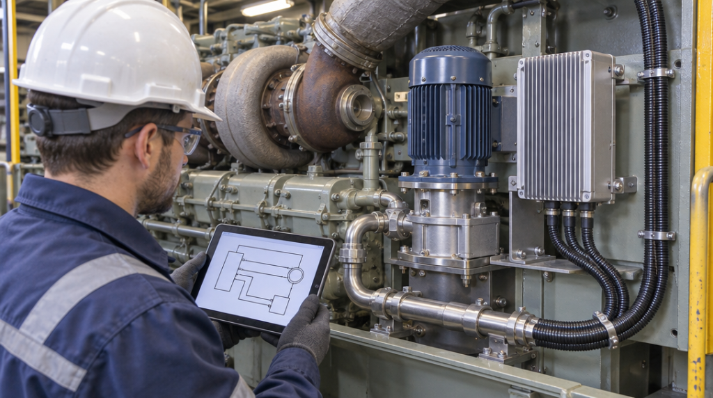
Many locomotives have been rebuilt, repowered or upgraded over their working lives, so the model designation alone is not a reliable guide. Confirm the engine actually installed and check the soak-back equipment fitted before specifying any change.
Compatibility checks before changing drive type
Changing from DC to inverter-driven AC, or replacing one AC design with another, involves more than swapping the pump assembly. Check the following before committing:
Supply voltage: confirm that the unit’s accepted input window covers your locomotive’s actual voltage range. This should include cranking dips and charging peaks.
Control circuit: the existing switch, timer and contactor were often designed around a DC motor. Confirm how the new unit is commanded to start and stop. Some inverters are switched by their DC supply, while others use a separate enable signal.
Contactor and breaker ratings: inverters can draw a brief surge at switch-on as their internal capacitors charge. Make sure the contactor and breaker are rated for it.
Wiring: check cable size, terminations and routing for the new current draw and connection point.
Locomotive control system: on microprocessor-controlled locomotives, check whether the control system monitors the soak-back motor’s current or feedback. A different motor type may trigger false fault reports unless the settings are updated.
Mechanical fit: check mounting, pipe connections and coupling arrangement against the installation drawing.
Environment: choose an inverter location with adequate ventilation, away from direct heat sources and with suitable vibration isolation.
Documentation: update wiring diagrams and maintenance records so future technicians know which system is fitted.
Comparing DC and AC setups: a decision guide
| Factor | Brushed DC motor | Inverter-driven AC motor |
|---|---|---|
| Power path | Direct from battery via contactor | Battery to inverter to motor |
| Speed as battery discharges | Falls to some degree | Held steady within input window |
| Routine motor maintenance | Brushes, commutator, bearings | Mainly bearings |
| Starting against cold oil | Strong torque from standstill | Depends on inverter and motor sizing |
| Electronics in power path | None | Inverter, sensitive to heat |
| Typical repair approach | Motor rebuild in the shop | Motor or inverter replaced as a unit |
| Built-in protection | Breaker only | Under-voltage, over-current and thermal, depending on design |
A brushed DC system may be the better fit when:
- Locomotives run in original configuration with DC soak-back equipment
- The depot has established DC motor repair capability
- Keeping the electrical system unchanged outweighs reducing maintenance
An inverter-driven AC system may be the better fit when:
- Brush and commutator wear is a recurring maintenance burden
- Locomotives shut down often, adding many post-shutdown running hours
- Battery condition varies and steady pump delivery on falling voltage is a priority
- The fleet already uses inverter-fed auxiliaries and the depot is set up to support them
Neither design is universally better. The right choice depends on the engine, the locomotive’s existing electrical and control systems, its operating pattern and the depot’s capabilities. When these are checked properly, either system can give long and reliable service.