

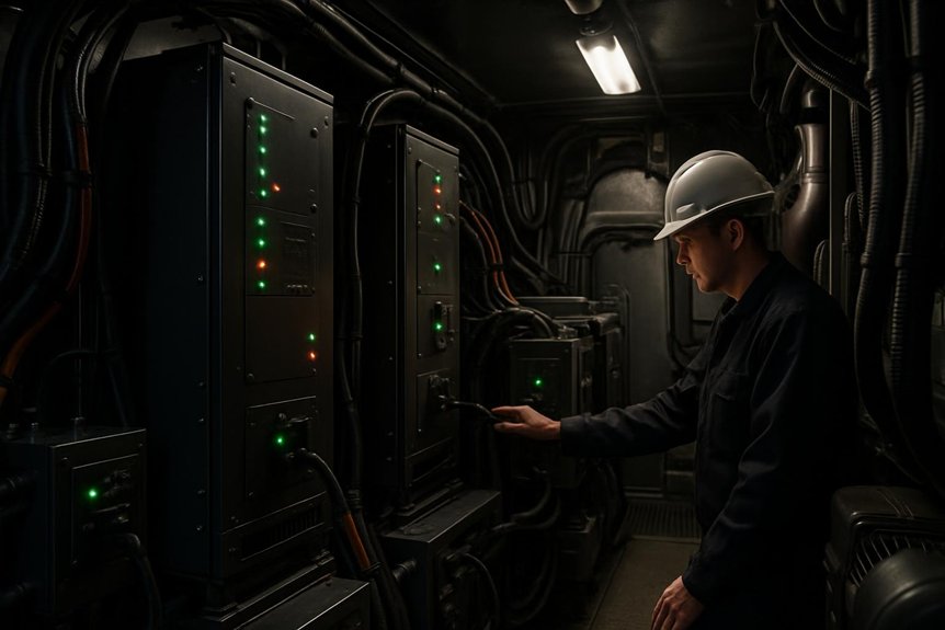
You protect EMD F125 HEP continuity with redundant inverter and auxiliary-genset sources, PLC supervision, protective relays, and split-bus isolation. The controller detects voltage, frequency, current, temperature, and breaker abnormalities, then isolates faults and transfers essential loads after synchronization and voltage ramping. Tiered shedding preserves lighting, communications, controls, and ventilation while reducing HVAC and discretionary loads. MU pass-through or authorized wayside power provides recovery options. Further details explain the transfer, protection, and contingency sequences.
What redundancy strategies exist for HEP continuity during inverter or auxiliary generator failures on the EMD F125?
HEP continuity ensures passenger comfort during power faults. The EMD F125 uses robust redundancy strategies effectively. Inverter failures trigger automatic auxiliary generator transfers instantly. Split-bus architectures isolate faults to preserve critical loads. Load shedding prioritizes HVAC and lighting systems first. MU pass-through allows power sharing from trailing units. Wayside shore power supports stationary locomotives at terminals. Diagnostic interlocks prevent unsafe paralleling of power sources.
Regular testing validates these complex safety protocols thoroughly. Engineers must understand these fail-safe mechanisms for reliability. Procurement specialists should value these integrated redundancy features. They minimize downtime and enhance operational efficiency significantly. Passenger experience remains uninterrupted during minor system glitches. This design reflects advanced railway engineering standards today. Safety compliance is maintained through rigorous verification processes. Redundant paths ensure no single point of failure. Control logic manages seamless transitions between power sources. Thermal budgeting prevents overloads during degraded operations. Crew indications guide proper response to fault events. Acceptance tests confirm system readiness before service entry.
Key Takeaways
- Main inverter and auxiliary genset provide separate HEP sources, enabling controlled transfer when the primary source fails or becomes capacity-limited.
- Split-bus distribution isolates damaged sections while preserving essential lighting, communications, control, and other healthy-car loads.
- PLC supervision monitors electrical and equipment conditions, recognizes failures, and coordinates source changes using breaker-position and system-status feedback.
- Protective relays and breakers rapidly isolate overcurrent, ground-fault, undervoltage, frequency, and backfeed conditions before faults cascade.
- Synchronization checks, voltage ramping, soft-start, and ride-through controls support stable, low-transient transfers to auxiliary HEP.
F125 HEP architecture overview

You’ll assess F125 HEP continuity through its inverter, auxiliary genset, and split-bus distribution paths.
You’ll also trace control and monitoring logic that detects faults and manages source transfers.
Finally, you’ll evaluate protection layers that isolate failures before they threaten essential locomotive loads.
Power sources and distribution
When the F125 operates normally, its main inverter supplies regulated three-phase 480 V HEP to passenger-car hotel loads. This path supports heating, ventilation, lighting, galley equipment, and other hotel services. You rely on the inverter for stable frequency and voltage across connected cars. An auxiliary genset provides a separate source when inverter capacity or availability declines. Its output supports essential HEP through transfer equipment, subject to approved synchronization and protection requirements.
The split-bus HEP architecture divides distribution into sections, limiting fault propagation and preserving service on healthy buses. Protective devices isolate short circuits before they disable every car. Prioritized feeders support essential lighting, communications, and life-safety loads during degraded operation. Thermal and capacity limits govern remaining loads. This arrangement strengthens hep continuity while reducing single-source exposure. You should verify cables, breakers, connectors, and grounding during scheduled maintenance.
Control and monitoring
PLC-based supervision coordinates the F125 HEP architecture while monitoring inverter, auxiliary genset, and split-bus conditions. You receive coordinated visibility through voltage, frequency, current, temperature, and breaker-position sensors. The controller compares measurements against operating limits, identifying unstable power before service continuity suffers. Its event logger timestamps alarms, source changes, bus separation, and recovery actions, giving you traceable evidence for troubleshooting and acceptance testing.
- Normal view: You see balanced voltage and frequency across energized HEP sections.
- Failure view: You see the controller recognize inverter loss and initiate auxiliary genset transfer.
- Recovery view: You verify stabilized readings before reconnecting available loads.
This monitoring framework supports emd f125 redundancy by exposing developing faults without relying on assumptions. You can review trends, confirm synchronization status, and correlate crew indications with recorded events. Maintenance teams should test sensors, timestamps, communications, and diagnostic interlocks routinely. That discipline reduces uncertainty during degraded operation and strengthens HEP continuity decisions.
Protection layers
Recorded measurements only protect operations when physical protection responds quickly. On the F125, you rely on breakers to interrupt excessive current before cables, inverters, or passenger loads sustain damage. Protective relays detect overcurrent, ground faults, undervoltage, and abnormal frequency, then command isolation or transfer sequences. This layered response limits fault energy and preserves HEP continuity across healthy sections.
Isolation transformers add galvanic separation between power-conversion equipment and downstream distribution. They help contain transients, reduce fault propagation, and protect passengers from hazardous touch voltages. Split-bus arrangements let you isolate a damaged section while retaining essential lighting, communications, and control loads.
You should verify trip settings, insulation resistance, transformer condition, and breaker coordination during scheduled maintenance. Acceptance testing must confirm selective operation, safe isolation, and correct auxiliary-genset transfer without unsafe source paralleling. Crew indications then support prompt, controlled recovery.
Failure modes and detection

You’ll monitor inverter signatures, including voltage deviation, thermal alarms, and protective trips.
You’ll also verify auxiliary genset faults through speed, frequency, voltage, and fuel-system indications.
Fault-isolation logic must identify the failed source, block unsafe paralleling, and preserve essential HEP loads.
Inverter failure signatures
Inverter controls monitor overcurrent, overtemperature, and gate-drive faults to detect failure signatures early. You’ll see protective relays isolate abnormal circuits before damage spreads through the HEP continuity path. This response supports EMD F125 redundancy while limiting passenger-service disruption.
- Overcurrent: A sharp current spike resembles a sudden surge through the inverter, prompting a trip or controlled shutdown.
- Overtemperature: Rising semiconductor or cabinet temperature signals cooling loss, overload, or restricted airflow; continued operation increases damage risk.
- Gate-drive fault: Missing or distorted switching commands reveal control-power, firing, or isolation problems, preventing safe power conversion.
Meanwhile, diagnostic interlocks block unsafe source paralleling and record event codes for troubleshooting. You should verify alarms against relay status, temperatures, and waveform data. Acceptance testing must reproduce protective thresholds without compromising live HEP loads. Such evidence confirms detection reliability before service entry.
Auxiliary genset failure signatures
Auxiliary genset failure signatures require monitoring fuel, cooling, overspeed, and voltage regulation alarms. You should treat each indication as a potential threat to HEP continuity, not an isolated warning. Fuel pressure loss can reduce engine output, while cooling alarms warn of thermal damage. Overspeed protection indicates uncontrolled mechanical acceleration. Voltage regulation alarms signal unstable excitation or unacceptable bus quality.
| Signature | Immediate risk | Detection evidence |
|---|---|---|
| Low fuel pressure | Output collapse | Pressure alarm, declining frequency |
| High coolant temperature | Engine trip | Temperature alarm, rising trend |
| Overspeed | Mechanical damage | Trip relay, speed excursion |
| Voltage deviation | Load instability | Regulator alarm, bus variation |
You’ll improve risk visibility by trending alarm duration, recurrence, and severity during inspections. Record these signatures alongside generator start failures and abnormal vibration. Maintenance teams should verify sensors, wiring, protective relays, and annunciators against approved limits. Acceptance testing must confirm accurate indications before service release. Don’t bypass alarms; escalation protects passengers, equipment, and recovery options.
Fault isolation logic
When a HEP fault occurs, protective relays must trip quickly, isolate the affected bus, and prevent backfeed. You’ll protect passengers and equipment by separating failed inverter sections from healthy circuits. Detection logic monitors overcurrent, undervoltage, insulation faults, frequency deviation, and phase imbalance. It confirms abnormal conditions before commanding transfer or load shedding.
- Overcurrent: A short circuit drives relay pickup, opens the feeder, and blocks reverse energization.
- Undervoltage: A collapsing bus signals source failure, isolates the section, and preserves essential services.
- Control fault: Failed feedback or interlocks inhibits paralleling, preventing unsafe source connection.
You’ll verify that breaker status, relay timing, and bus-voltage indications agree. Diagnostic records should identify the initiating fault and unsuccessful transfer attempts. Maintenance teams must test trip curves, interlocks, and insulation regularly. This disciplined isolation limits arc-flash exposure, equipment damage, and cascading HEP loss.
Automatic transfer and HEP continuity

When you detect an inverter fault, you’ll initiate controlled auxiliary genset transfer to preserve HEP continuity. Synchronization and voltage ramping limit transients, protecting passenger loads and split-bus equipment. Ride-through controls then manage essential services while you verify stable operation and prevent unsafe source paralleling.
HEP continuity during inverter faults
During an inverter fault, the F125 detects abnormal voltage, frequency, or current conditions through protective relaying. You’ll see the control system isolate the failed path, protecting passengers and connected equipment. Automatic transfer logic then prepares the auxiliary genset for HEP service without unsafe source paralleling. The sequence preserves HEP continuity by validating availability, phase, and frequency before connection.
- Protective relays trip the inverter, while interlocks block backfeed and contain the fault.
- Control logic confirms auxiliary genset readiness, then transfers prioritized loads through the split-bus architecture.
- You’ll retain essential lighting, communications, ventilation, and safety systems while noncritical demand remains shed.
Crew indications identify the affected source and required response. Maintenance teams should verify relays, breakers, transfer controls, and genset capacity during acceptance and periodic testing. Record transfer times, voltage stability, and alarm performance. This evidence supports compliance, procurement decisions, and dependable EMD F125 operation. When onboard capacity remains restricted, coordinate approved MU or wayside contingencies.
Synchronization and ramping
Once protective relays isolate the inverter, synchronization controls prepare the auxiliary genset for bumpless HEP transfer. You verify voltage, frequency, phase angle, and breaker permissives before closing the transfer path. The controller then soft-starts the genset, ramps voltage, and limits inrush current, protecting HVAC drives, lighting supplies, and electronic loads. This sequence prevents torque shocks, nuisance trips, and unsafe source paralleling.
| Control stage | Primary risk | Required verification |
|---|---|---|
| Synchronize | Phase mismatch | Voltage, frequency, angle |
| Soft-start | Inrush stress | Current and ramp limits |
| Transfer | Open transition fault | Interlocks and breaker status |
After connection, you monitor bus frequency, voltage, load share, and thermal margin. Load-priority logic keeps essential services within auxiliary capacity. Maintenance teams should trend transfer times, ramp profiles, and failed permissives during scheduled tests. Acceptance records demonstrate HEP continuity, protect passengers, and support fleet availability. Crew indications confirm the source and any restricted loads.
Ride-through strategies
- Detect: Relays isolate the failed inverter, while controls confirm source availability and block unsafe paralleling.
- Transfer: Automatic logic synchronizes voltage and frequency, then connects the genset through the split-bus architecture.
- Prioritize: You’ll preserve essential lighting, communications, controls, and safe HVAC operation before shedding discretionary demand.
Thermal limits govern remaining loads during degraded operation. MU pass-through or wayside power can support recovery when onboard sources remain unavailable. Verify every sequence through acceptance testing, fault injection, and maintenance inspections. Crew indications must clearly identify source status, shed tiers, and required response. This disciplined approach reduces passenger disruption and protects equipment.
Load management and split-bus resilience

You’ll protect HEP continuity by applying tiered load shedding as available capacity declines.
A split-bus HEP architecture isolates faults, while thermal and power budgeting limits cascading overloads.
This approach keeps essential lighting, controls, and safety services energized during degraded operation.
Tiered load shedding
When HEP capacity falls after a fault, tiered load shedding protects essential services through deliberate, sequenced disconnection. You should define priorities before degraded operation begins, matching control logic to verified thermal and electrical limits. The sequence should preserve:
- First tier: Maintain door control, emergency lighting, communications, and safety monitoring while isolating nonessential hotel loads.
- Second tier: Reduce HVAC demand progressively, limiting compressor operation while retaining ventilation and passenger protection.
- Third tier: Disconnect deferables, such as galley equipment, convenience outlets, and selected auxiliary services, preventing overload.
Protective relays and diagnostics should confirm each step, blocking unsafe restoration or unexpected reclosing. Crew indications must identify the active tier and remaining capacity. You should validate timing, recovery, and alarm behavior during acceptance and maintenance testing. This disciplined approach sustains HEP continuity, limits thermal stress, and supports controlled recovery.
Split-bus HEP architecture
Split-bus HEP architecture extends tiered load shedding by separating hotel power across A and B buses. You can isolate a failed feeder, inverter section, or protection zone while preserving service on the healthy bus. Each bus should supply defined essential loads, including emergency lighting, communications, controls, and selected ventilation. Protective relays detect abnormal current or voltage, then trip only affected sections. Consequently, passengers may retain partial lighting and climate service during localized faults.
Automatic transfer logic must prevent unsafe source paralleling and confirm contactor position before reconfiguration. Your crew should verify bus status through clear indications and follow approved isolation procedures. MU pass-through or wayside power can support remaining services when onboard sources fail. Acceptance testing should prove fault isolation, transfer interlocks, and recovery sequences under controlled conditions. This architecture limits single-point failures without masking degraded operation.
Thermal and power budgeting
Thermal and power budgeting protects HEP continuity by separating continuous demand from short-duration peak kW. You must size each split-bus section for sustained thermal loading, then verify surge capacity during HVAC starts and compressor cycling. This prevents overloaded conductors, inverter trips, and unnecessary auxiliary genset transfers.
- Measure the baseline: Record lighting, controls, battery charging, and HVAC demand before calculating available margin.
- Rank the loads: Keep emergency lighting, ventilation, communications, and control circuits energized before nonessential comfort loads.
- Verify degraded operation: Test one-bus operation, shedding thresholds, breaker coordination, and recovery without exceeding thermal limits.
Your control logic should shed lower-priority loads before protective relays trip. Meanwhile, operators need clear indications when capacity falls. Maintenance teams should trend temperatures, current imbalance, and repeated overload events. Acceptance testing must confirm calculated budgets under realistic passenger-service conditions. This approach preserves HEP continuity while limiting equipment damage and cascading failures.
External and procedural contingencies
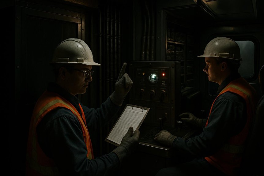
You’ll preserve HEP continuity by using MU pass-through or rescue power when onboard sources fail.
At terminals, you’ll apply wayside shore power through verified isolation and connection procedures.
Scheduled testing and maintenance will confirm transfer logic, protection, interlocks, and crew response readiness.
MU pass-through and rescue
When onboard HEP sources fail, MU pass-through lets the F125 receive hotel power from another locomotive through approved jumper connections and controls. You must verify compatible voltage, frequency, phasing, ratings, and trainline integrity before energizing the consist. Isolation procedures prevent backfeed, unintended paralleling, and personnel exposure during connection.
- Confirm the failed unit, open its source breakers, and apply required lockout controls.
- Inspect jumper condition, connector seating, grounding, and communication between operating crews.
- Close pass-through controls only after authorization, then monitor current, voltage, alarms, and thermal margins.
Your crew should maintain essential lighting, ventilation, communications, and control systems within the supplying locomotive’s capacity. Load shedding remains necessary if demand exceeds available HEP. Rescue planning should identify compatible locomotives, qualified personnel, recovery routes, and passenger-management steps. Afterward, record alarms, operating duration, and test results for corrective maintenance. Never bypass interlocks or improvise connections.
Wayside shore power
At a terminal, wayside shore power can stabilize passenger services after onboard HEP sources become unavailable. You’ll connect an approved external supply through the designated interface, following site isolation and authorization procedures. The connection supports hotel loads while you protect the locomotive from backfeed, phase errors, and unsafe paralleling. Confirm onboard sources remain isolated before energizing the shore circuit. Coordinate with dispatch, terminal staff, and train crews, because an incorrect sequence can interrupt lighting, ventilation, communications, or passenger information.
| Risk | Control | Operational result |
|---|---|---|
| Backfeed | Apply lockout and verify isolation | Protects personnel |
| Phase mismatch | Confirm supply compatibility | Prevents equipment damage |
| Overload | Prioritize essential loads | Preserves critical services |
| Loss of shore power | Prepare controlled retransfer | Limits interruption |
You should maintain a documented fallback: secure nonessential loads, notify passengers, and prepare battery-backed communications. Treat wayside power as a contingency, not a replacement for onboard HEP redundancy. Record source status and crew indications throughout the transfer.
Testing and maintenance
Reliable HEP continuity depends on disciplined testing beyond onboard hardware. You should schedule periodic drills that simulate inverter trips, auxiliary genset transfer, split-bus isolation, and MU pass-through. These exercises expose timing, communication, and crew-response risks before service disruption.
- Test breakers: Verify protective-relay operation, interlocks, transfer logic, synchronization, and load-shedding tiers under controlled conditions.
- Inspect contingencies: Confirm wayside-power connections, rescue procedures, essential-load definitions, and documented isolation steps.
- Update controls: Apply validated firmware updates, then repeat acceptance tests, event-log reviews, and failover demonstrations.
You should record results against maintenance intervals, configuration baselines, and compliance requirements. Technicians must investigate nuisance trips, overheating, abnormal transfer times, or failed indications immediately. Procurement teams should require traceable test records and replacement support. This discipline reduces single-point exposure and strengthens HEP continuity across degraded operating scenarios.
Frequently Asked Questions
Which Certifications Govern F125 HEP Redundancy Acceptance and Documentation?
You’ll typically govern F125 HEP redundancy acceptance through FRA regulations, applicable APTA standards, IEEE power-quality practices, and the locomotive’s approved safety and design basis. Certification requirements can also include EMC, fire, electrical shock, and software assurance evidence, depending on contract scope and operating jurisdiction. Require documented failure-mode analysis, protective-relay tests, transfer-sequence validation, insulation results, load-shed verification, and traceable configuration control. Don’t accept supplier claims without witnessed testing and signed records.
How Should Procurement Teams Compare Lifecycle Costs for Redundant HEP Components?
How should you compare lifecycle costs for redundant HEP components? Build a total-cost model, not a purchase-price table. Include acquisition, installation, commissioning, energy use, inspections, spares, software support, overhaul intervals, and disposal. Then quantify downtime exposure, passenger-service disruption, and failure-response labor. Compare inverter and auxiliary-genset scenarios using reliability data, warranty terms, and maintainability targets. You’ll identify the lowest-risk option, even when its initial price exceeds alternatives.
What Spare Parts Strategy Supports Long-Term F125 HEP Availability?
You’ll protect long-term F125 HEP availability with a risk-ranked spares strategy covering inverters, auxiliary genset components, contactors, relays, sensors, cooling hardware, and control modules. Stock serialized, configuration-controlled parts according to failure rates, lead times, and fleet criticality. Maintain preservation, inspection, and traceability records. Include repairable-unit exchange pools and approved substitutes. Validate every replacement through insulation, protection, synchronization, and load-transfer tests before return to service.
How Are HEP Control-System Software Updates Validated Before Fleet Deployment?
You validate HEP control-system software updates through staged, evidence-based testing before fleet deployment. First, you’ll review requirements, cybersecurity controls, interfaces, and fail-safe logic. Next, hardware-in-the-loop testing simulates inverter faults, auxiliary genset transfers, load shedding, MU pass-through, and split-bus isolation. Engineers then conduct laboratory integration and controlled locomotive trials. Independent reviewers assess results against approved acceptance criteria. Finally, you’ll authorize phased release, monitor diagnostics, and retain rollback capability for safe, reliable fleet operation.
Which Supplier Records Help Verify Replacement Inverter and Generator Component Traceability?
You should obtain certificates of conformity, manufacturer part numbers, serial-number records, lot codes, and supplier invoices. Request material certificates, inspection reports, repair histories, and authorized-distribution evidence. Confirm each record matches the component, locomotive, purchase order, and installation date. Preserve receiving inspections, firmware versions, and test results within your asset system. This chain supports HEP continuity, detects counterfeit parts, and enables targeted recalls. Require supplier quality agreements defining retention, access, and audit rights.