

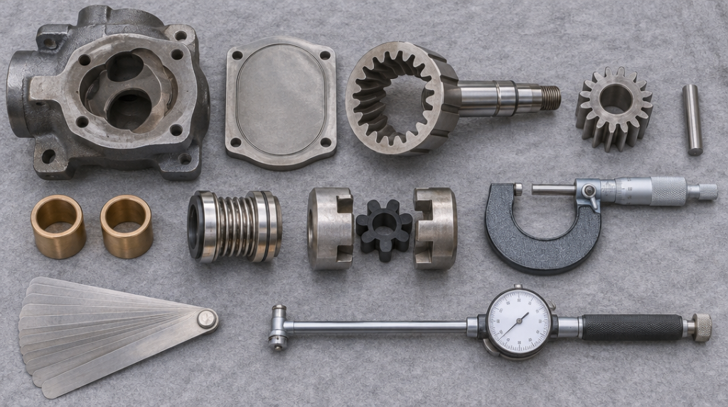
A soak-back pump that has been diagnosed as faulty and removed from the locomotive raises a new set of questions. Which parts have worn? Can the unit be rebuilt, or should it be scrapped? And what caused the failure in the first place? The answers are inside the pump, but only if the teardown is done carefully and the evidence is read correctly.
This guide covers that process for a removed pump on the bench. It explains what each internal component does and how to disassemble the pump without losing evidence. It then sets out what to measure and inspect, and how to interpret the wear you find. It assumes the fault has already been confirmed as internal to the pump.
Clearances, tolerances and torque values differ between pump designs and build standards, so always use the overhaul manual for your specific unit. This guide explains what to check and why, while your manual supplies the limits that decide pass or fail.
Anatomy of a Soak-Back Pump
How the rotor-and-idler design moves oil
Most locomotive soak-back pumps are positive-displacement internal gear pumps built around two moving parts, a rotor and an idler gear. Confirm the design of your unit in its manual, as configurations vary.
The rotor is the outer, driven member, with internal teeth and an integral or attached drive shaft. The idler is a smaller gear with external teeth. It sits off-centre inside the rotor and meshes with it on one side. On many designs, a crescent-shaped segment fills the gap between the two on the opposite side.
As the rotor turns, it drives the idler. On the inlet side, the teeth come out of mesh and open up spaces that fill with oil. The oil is carried around in the pockets between the teeth and the crescent. On the outlet side, the teeth re-mesh and force it out.
This design depends on tight running clearances. Oil leaks back from the outlet to the inlet through every gap between moving and stationary parts. As those gaps grow with wear, more oil slips back internally and less reaches the outlet. This is why a worn pump can run smoothly yet deliver well below its rated output.
Housing, cover and idler pin
The housing is the main casting. It contains the rotor bore, the inlet and outlet ports, and the mounting faces. Its bore must stay round and concentric with the shaft bushing for the rotor to run true.
The cover closes the pumping chamber and usually carries the idler pin, and on crescent designs the crescent as well. The cover’s inner face forms one side of the pumping chamber. The clearance between this face and the rotor and idler faces, known as end clearance, is one of the most important dimensions in the pump. Too much end clearance is a major source of internal slip.
The idler pin is a fixed, hardened pin that the idler gear rotates on. It is offset from the rotor centreline by a set amount. Any wear or looseness in the pin changes how the gears mesh, reduces efficiency and can cause tooth contact in the wrong places.
Gaskets or O-rings between the cover and housing seal the chamber. Shims are also used on some designs, and their thickness sets the end clearance.
Shaft seal, bushings and drive coupling
The rotor shaft runs in a bushing in the housing. The idler gear runs in its own bushing on the idler pin. These are plain bearings lubricated by the oil being pumped. Wear quickly when that oil is dirty or when the pump runs dry.
Where the rotor shaft leaves the housing, a bellows-type mechanical seal prevents oil leakage. It has two parts:
- Seal face: a stationary face that a rotating face runs against
- Bellows: a flexible element that holds the faces together and allows for small shaft movements
The faces are lapped extremely flat, and a thin oil film between them provides both sealing and lubrication.
The pump is driven by the motor through a flexible jaw coupling. Two metal hubs with interlocking jaws are separated by an elastomer insert, often called a spider. The spider absorbs shock loads and small misalignments between the motor and pump shafts. It is designed to be the sacrificial part of the drive, and its condition says a lot about how the pump has been running.
Teardown: Disassembling the Pump for Inspection
Preparing the bench and recording as-found condition
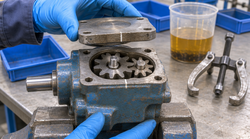
Before removing a single fastener, inspect and record the pump exactly as it came off the locomotive. Photograph it from all sides.
Note:
- External leaks or wetness, especially around the shaft seal and cover joint
- Missing or damaged fasteners
- Paint disturbance suggesting previous dismantling
- Impact damage
Turn the shaft by hand and note how it feels. Roughness, tight spots, binding or excessive free play all point to specific internal problems. Feel for end play and side play at the shaft, and record whether either seems excessive.
Drain the remaining oil into a clean, clear container and keep it. Its colour, smell and any debris it carries are part of the evidence. Metallic particles, carbon, sludge or water each point to a different cause. A small sample can also be sent for analysis if the failure is part of a wider fleet problem.
Work on a clean bench covered with lint-free material. Have trays ready to keep parts separated and in order.
Disassembly sequence
Follow the sequence in your overhaul manual. The general approach for a rotor-and-idler pump is outlined below.
- Separate the drive: remove the coupling hub from the pump shaft using a suitable puller. Never hammer the shaft, as shock loads can damage the bushings, the seal faces and the rotor.
- Mark the cover: before removing the cover, make match marks across the cover-to-housing joint so it can be refitted in its original position.
- Remove the cover: loosen the bolts evenly and lift the cover straight off to avoid dragging the idler across the rotor. Collect any shims as a set and measure their total thickness, as they tell you the original end clearance setting.
- Mark the idler: before lifting it out, mark which face points toward the cover. Idlers often wear unevenly, and refitting one the other way round can make a marginal pump worse.
- Remove the rotor: withdraw the rotor and shaft carefully through the housing, supporting the weight so the shaft does not drag across the bushing.
- Remove the seal: take out the mechanical seal last, keeping the seal faces apart and protected from scratches.
Cleaning without destroying evidence
Inspect every part before cleaning it. Deposits, discolouration and debris patterns are often washed away with the oil, along with the clues to the root cause. Photograph the rotor, idler, cover face and bushings as found, under good light.
Then clean the parts in a suitable solvent using soft brushes. Avoid:
- Wire brushes and abrasive pads on any running surface
- Scrapers on lapped seal faces or machined sealing faces
Blow out the internal passages with clean, dry compressed air, wearing eye protection.
Dry all parts fully and lay them out in order. Keep matched pairs together, such as the idler and its pin, and the rotor and its bushing. If the pump is to be rebuilt, protect machined surfaces with a light film of clean oil and cover them until reassembly.
Wear Points and Inspection Criteria
Rotor and idler gear: teeth, faces and clearances
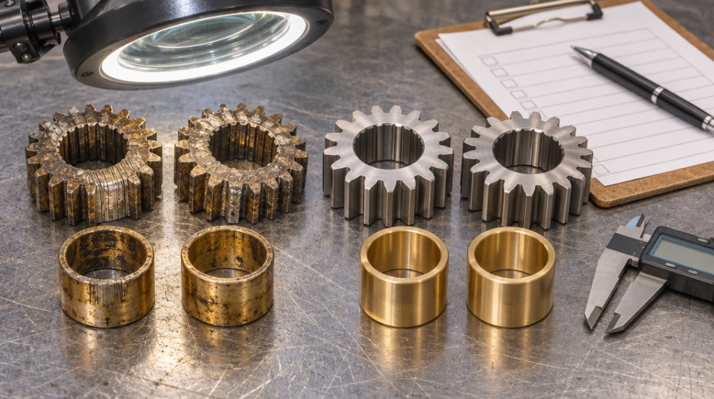
Inspect the teeth of both the rotor and the idler under good light, ideally with magnification, looking for:
- Pitting: small craters on the tooth flanks, a sign of fatigue or cavitation
- Scoring: lines across the teeth in the direction of rotation, a sign of abrasive particles
- Chipped or cracked teeth: these usually mean a hard object passed through the pump, or the pump seized
- Polished patches in unexpected places, which point to contact where there should be none
Then examine the flat faces of both gears. Circular scoring on the faces means debris has been trapped between the gears and the cover or housing. Use a straightedge to check the faces for flatness.
Measure the critical clearances with feeler gauges, micrometers and a depth gauge as your manual specifies:
- End clearance: between the gear faces and the cover
- Tip clearance: between the tooth tips and the crescent, where one is fitted
- Radial clearance: between the rotor’s outside diameter and the housing bore
Compare each figure with the manual’s new and wear limits. Each is a direct path for internal slip.
Bushings, idler pin and shaft: wear and running clearance
Check the rotor shaft bushing and idler bushing for:
- Scoring and uneven wear
- Embedded particles
- Loss of the bearing material in patches
- Signs of the bushing turning in its bore
Measure each bushing’s inside diameter at several points, both along its length and around its circumference, with a bore gauge or inside micrometer. This shows wear and also tapering or ovality.
Measure the mating surfaces as well: the shaft journal where it runs in the bushing, and the idler pin. Look for:
- Grooves, scoring or ridges on the shaft journal
- A flat spot on the idler pin, which shows the idler has been loaded heavily on one side
Subtract the journal or pin diameter from the bushing bore to calculate running clearance, and compare it with the limits in the manual.
Excessive bushing clearance lets the rotor and idler move off-centre under pressure. That accelerates wear on the tooth tips, faces and housing bore. A pump with worn bushings will soon wear out everything else as well, so these figures carry particular weight in the overhaul decision.
Bellows seal, coupling spider, housing and cover
Bellows seal: inspect the seal faces for cracks, chips, heat checking (fine surface cracking), grooving and uneven wear tracks. A wear track that is off-centre or wider on one side suggests shaft misalignment or bushing wear. Check the bellows for:
- Splits
- Hardening
- Swelling
- Loss of spring force
Seals are normally replaced at overhaul, but their condition still helps explain why the pump failed.
Coupling spider: check for cracking, hardening, missing segments, melting or compression set (permanent flattening). Inspect the coupling hub jaws for wear or peening.
Housing and cover:
- Check the cover’s inner face for scoring and flatness.
- Inspect the housing bore for scoring, ovality and step wear.
- Check all castings for cracks, particularly around bolt holes and ports.
- Inspect threads for damage.
- Check gasket faces for corrosion or nicks that could cause leaks.
Interpreting Findings and Deciding the Next Step
Common wear patterns and what causes them
Identifying the cause is just as important as identifying the worn parts. Without it, a rebuilt or new pump may fail the same way. These patterns appear often:
- Fine scoring on gears, faces and bushings: abrasive particles in the oil. Look at filtration and oil change intervals, and at sources of contamination such as wear debris from elsewhere in the engine.
- Discolouration, varnish or heavy smearing on bushings: overheating or running dry. This often points to suction-side starvation, very low oil level or degraded oil.
- Pitting on tooth flanks and pump surfaces near the inlet: often cavitation, where oil vaporises under suction and the bubbles collapse against metal. Restricted inlet passages and oil that is too thick or aerated are typical causes.
- One-sided or diagonal wear on gears, seal faces and bushings, plus a damaged spider: misalignment between motor and pump, or a worn or bent shaft.
- Chipped teeth or a gouged crescent: a hard foreign object passing through the pump.
- Uniform, gradual wear with clean surfaces: normal wear at the end of service life.
Repair or replace: making the call
The overhaul decision should rest on measured figures against manual limits rather than on appearance. Sort components into three groups.
Consumables, replaced at every overhaul whatever their condition:
- Shaft seal
- Gaskets and O-rings
- Coupling spider
Reusing these to save a small cost puts the whole rebuild at risk.
Wear parts: bushings and the idler pin are usually replaced when they are outside limits, and often as a matter of course.
Major components: the rotor, idler, housing and cover call for more judgement:
- If the gears are within limits and undamaged, they can usually be reused.
- If end clearance is excessive but the faces are sound, some designs allow adjustment with shims or face machining within manual limits.
- Heavily scored, cracked or out-of-limit major components should be replaced.
When several major components are out of limits at once, a full replacement assembly is often more economical and more reliable than a rebuild. Consider labour, parts, test equipment and downtime together.
Documenting findings for the fleet record
Record the results of every teardown:
- Locomotive number, pump serial number and service hours or dates
- As-found condition and photographs
- Every measured clearance against its limits
- The identified root cause
- The overhaul decision and the parts replaced
Over time, these records form a valuable fleet database. They show:
- Typical service life between overhauls
- Which components wear first
- Whether certain locomotives, operating patterns or oil practices produce more failures than others
Repeated contamination wear across several units, for example, points to a fleet-wide filtration issue rather than individual pump faults.
Clear records also support warranty claims, make it easier to schedule overhauls before failure, and give the next technician a reliable baseline when the same pump returns to the bench.