

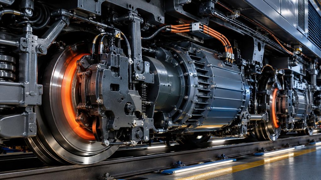
On the EMD F125, you command a braking level, and its control system coordinates traction-motor dynamic braking with pneumatic friction brakes to meet the requested effort. As speed falls or dynamic capacity is limited, pneumatic braking supplies the shortfall; at low speeds, it supports precise stopping. This blend can reduce brake-shoe and disc contact, wear, and heat when dynamic braking is available. Recovered energy may serve compatible loads or storage; otherwise, resistors dissipate it as heat. The details explain how the system adapts.
How Do Dynamic and Friction Brakes in Locomotives Differ?
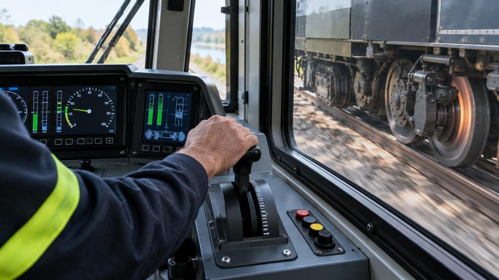
Dynamic braking slows a locomotive by converting traction-motor energy into electrical energy, which onboard resistors dissipate as heat. On the EMD F125, this electrical braking creates retarding force without applying brake shoes or discs. You’ll see its effectiveness depend on speed, motor capability, resistor capacity, and control settings. The dynamic braking response can change as operating conditions shift, so crews and engineers monitor system performance.
Friction braking uses pneumatic force to press shoes against wheels or calipers against discs. That contact converts kinetic energy into heat at the friction surfaces, producing reliable braking at low speeds and when electrical braking isn’t available. You’ll need to account for wear, inspection intervals, and thermal limits during maintenance planning.
Regenerative braking limits matter because returning generated electricity to a usable supply requires compatible infrastructure and operating conditions. Where energy can’t be accepted, onboard resistors dissipate it instead. These systems serve distinct functions; understanding their limits helps you assess component condition, operating requirements, and maintenance needs across your locomotive fleet.
How Does the F125 Blend Both Brake Types?
On the EMD F125, you command a braking level, and the control system allocates effort between dynamic and friction brakes. It coordinates their inputs to meet the requested deceleration while managing brake-system limits. You’ll see how this integration supports controlled, consistent braking.
Blending Brake Inputs
In the EMD F125 Locomotive, the brake control system coordinates dynamic braking with pneumatic braking to meet the requested effort. You set a braking demand; controller mapping converts it into a dynamic torque command and a calibrated friction-brake contribution. Dynamic braking uses traction alternator output to slow the locomotive, while pneumatic brakes supply the remaining effort. Control logic adjusts this split as speed and operating conditions change, helping avoid abrupt torque steps. Wheel-slip control can limit available dynamic effort when adhesion falls, so friction braking helps maintain the requested deceleration. At low speed, pneumatic braking supports precise control and final stopping. By using electrical braking where available, you reduce heat and wear at shoes or discs. Energy recovery depends on system capability; safe deceleration remains the priority for your fleet.
Coordinating Brake Systems
During a brake command, the EMD F125 Locomotive’s controller coordinates dynamic and pneumatic effort against the requested deceleration. You’ll see the system allocate braking demand while accounting for locomotive speed, available traction-motor retarding capacity, and pneumatic response. Brake control laws govern how effort shifts as speed falls or electrical limits constrain dynamic braking. Sensor fusion logic combines relevant command and feedback signals, helping the controller assess whether delivered braking tracks the requested rate. When dynamic effort cannot meet demand, pneumatic brakes supply the shortfall; as dynamic capacity changes, pneumatic effort adjusts accordingly. This coordination supports controlled deceleration without assuming either brake type can always provide the full demand. For your engineering review, confirm the specific operating limits and control behavior in F125 documentation. That evidence helps you evaluate performance, maintenance implications, and energy recovery potential accurately.
When Does the F125 Need Friction Brakes?
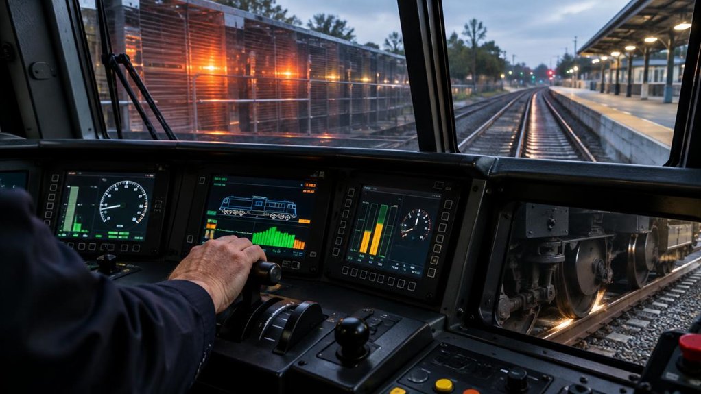
When dynamic braking cannot provide enough retardation, the EMD F125’s blended braking system applies friction brakes to meet the requested braking effort. You’ll see this when operating conditions or braking demands exceed the dynamic system’s available capacity. The controller coordinates both sources to maintain commanded deceleration.
> When dynamic braking falls short, the EMD F125 blends in friction brakes to deliver the requested deceleration.
- At low speeds, dynamic braking produces less retarding force, so friction brakes support low speed stopping needs and help you complete a controlled stop.
- On low-adhesion track or with a heavy consist, dynamic braking may not meet the requested effort. Friction braking supplies the additional force needed to meet the braking command.
- During emergency applications, friction brakes provide dependable stopping effort when dynamic braking alone can’t satisfy the demand.
For maintenance planning, review friction wear indicators and brake inspection intervals against recorded duty and inspection findings. Before service, confirm blending readiness checks, including relevant brake-system status and fault indications. These checks help you identify issues before they disrupt locomotive availability or scheduled operations. When performance differs from expected behavior, investigate the control system and brake equipment using approved procedures.
How Does F125 Blended Braking Reduce Wear?
Blended braking reduces friction-brake wear by using dynamic braking to supply retarding effort when conditions allow. On the EMD F125 Locomotive, the control system coordinates dynamic and friction braking to meet the requested deceleration. You’ll see less brake-shoe and disc contact when dynamic effort can safely provide part of that demand.
Brake wear causes include repeated friction, high contact pressure, heat, and operating conditions. Blended control can limit friction-brake applications, reducing heat cycles and material loss. It can’t eliminate wear: low speed, adhesion limits, or equipment constraints may require more friction braking.
For your maintenance diagnostics, compare brake-component condition with operating records and braking performance. That helps identify uneven wear, dragging components, or control issues before they increase downtime. Material selection also matters; approved friction materials must match system requirements and service conditions. Effective thermal management helps control temperatures during demanding stops, protecting components from excessive heat. Together, these measures support predictable inspections and longer component service intervals, without compromising required braking performance.
What Happens to Recovered Braking Energy?
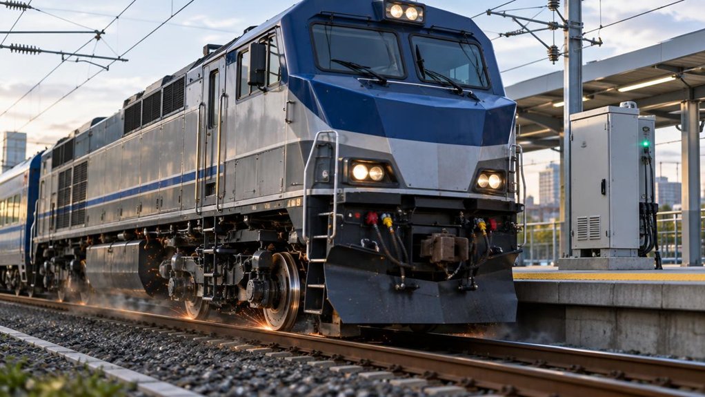
Where does braking energy go on the EMD F125 Locomotive? During deceleration, traction motors can act as generators, converting wheel-driven motion into electrical energy. Regenerative braking describes this process; the actual destination depends on the locomotive’s electrical architecture and operating conditions.
- Onboard reuse: If the system supports it, recovered power can supply compatible auxiliary loads or charge energy storage. This onboard reuse reduces demand on engine-driven generation, but only when equipment and controls permit.
- Grid export: Grid export requires suitable electrical connections and infrastructure. Don’t assume the F125 sends braking power to a wayside grid; verify the configuration and operating documentation.
- Dissipation: When neither reuse nor export is available, braking energy may be routed to resistors and released as heat. Friction brakes then provide the required stopping force and blend with dynamic braking as conditions change.
For your fleet, confirm energy capture capability, limits, and control behavior from approved technical data. That evidence helps you assess efficiency without overstating recoverable energy.
Frequently Asked Questions
What Maintenance Records Help Assess Blended-Braking Performance on an EMD F125 Locomotive?
Keep your finger on the pulse by reviewing records that connect brake commands, system response, and component condition. You’ll need event logs showing each Brake Event, including speed, braking effort, and regenerative contribution. Compare these with inspection reports, brake shoe and disc measurements, replacement dates, and Wear Trends. Include fault codes, control-system downloads, and maintenance work orders. Together, these records help you identify performance changes, investigate discrepancies, and plan evidence-based servicing for your EMD F125 locomotive.
Which Diagnostic Data Can Indicate a Fault in the F125’s Braking Control System?
You can identify F125 braking-control faults by comparing brake-pipe pressure, commanded and actual cylinder pressure, wheel-speed signals, and brake blending requests. Review event logs for pressure deviations, delayed responses, unexpected pneumatic application, or communication errors. Brake diagnostic trends across operating conditions help distinguish sensor drift from valve or controller problems. Use fault isolation methods to correlate alerts with test results and maintenance history; confirm findings before replacing components to limit unnecessary downtime and cost.
How Should Engineers Inspect Brake Rigging After Repeated Blended-Braking Cycles?
After repeated blended-braking cycles, inspect the EMD F125 brake rigging under your approved maintenance procedures. Check pins, bushings, hangers, levers, and connections for looseness, cracking, corrosion, or abnormal wear. Use Brake Wearchecks to compare shoe wear across wheels and identify uneven contact. Verify Rigging Alignment against manufacturer tolerances, then confirm free movement and secure fasteners. Record findings and investigate recurring discrepancies before returning the locomotive to service; don’t rely on visual checks alone.
What Operating Conditions Can Affect Blended-Braking Calibration on the F125?
You can see EMD F125 blended-braking calibration shift with speed, axle loading, wheel-slide protection inputs, and changing track conditions. Wheel slip sensitivity matters because contamination or uneven rail adhesion can prompt control systems to reduce dynamic braking and increase pneumatic demand. Grade adhesion effects also change available braking effort, especially on wet, oily, or leaf-covered rails. Monitor wheel-speed signals, brake-cylinder response, and event logs; verify calibration against approved procedures after relevant software, sensor, or brake-system changes.
Which Replacement-Part Specifications Should Procurement Teams Verify for F125 Brake Systems?
The perfect brake part is the one you never notice—until the wrong specification stops service. For your EMD F125 Locomotive, verify shoe material, lining thickness, dimensions, mounting pattern, and approved operating temperature. Confirm disc compatibility, actuator interfaces, and supplier traceability against locomotive maintenance documentation. Check certificates and inspection records before ordering; matching these details helps you control wear, maintain braking performance, and reduce avoidable downtime. Mikura International can support your locomotive parts requirements with experienced technical guidance.