

What Should Be Inspected on the Turbine Housing and Nozzle Components of EMD 710 Turbochargers During Locomotive Overhauls?
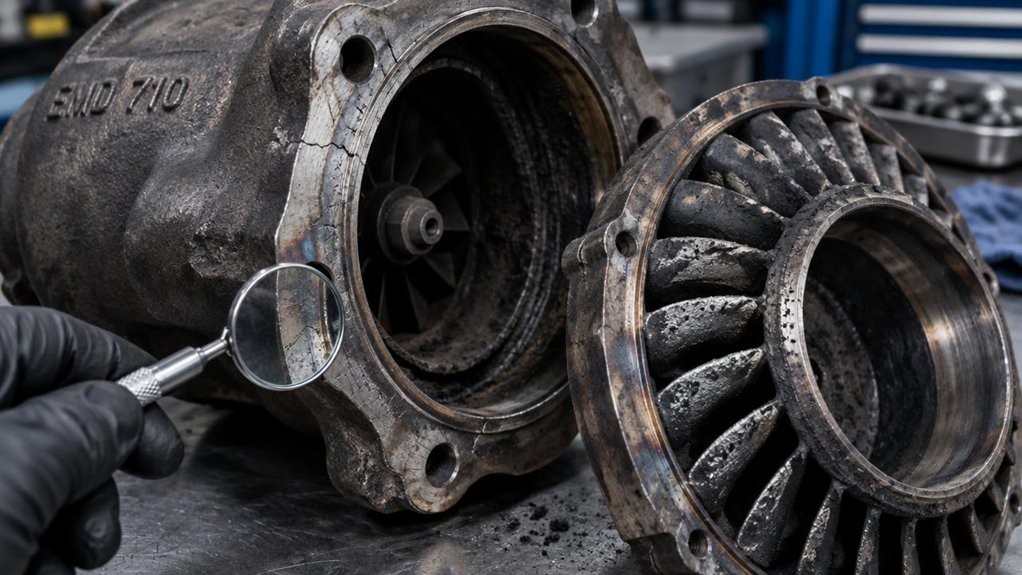
For EMD 710 turbocharger inspection, start with the turbine housing and nozzle assemblies. Inspect housings for cracks, erosion, corrosion, distortion, and damaged mating surfaces. Check mounting flanges, bolt holes, insulation, alignment marks, and heat shields. Record all findings against OEM overhaul limits and locomotive service history.
Inspect nozzle rings and vanes for cracking, erosion, carbon buildup, and distortion. Verify vane angles, clearances, shroud condition, and fastener integrity. Confirm that passages are clean and free of blockage. Use the correct measuring tools and OEM limits. Document nozzle ring wear and vane damage for repair decisions.
Perform nondestructive testing on critical surfaces and weld areas. Check fit-up, runout, and sealing surfaces before approval. Track part numbers, repairs, and test results for procurement decisions. Reject components that exceed locomotive overhaul limits. Confirm replacement parts meet EMD dimensional and material specifications. Review supplier traceability and cleaning records. Document final disposition. Retain photos and measurements.
EMD 710 turbocharger inspection: Housing and Nozzle Scope
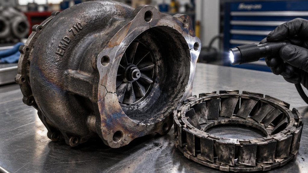
Before you measure anything on an EMD 710 turbocharger, you’ll need to clean and tag every component so findings stay tied to the right locomotive and part. Once the surfaces are clean, you can work through the visual checkpoints on the turbine housing and nozzle assembly. Keep your OEM limits and the unit’s service history at hand, because every observation gets recorded against them.
EMD 710 turbocharger inspection: Pre-Cleaning and Tagging
A solid EMD 710 turbocharger inspection starts in the wash bay, not at the measuring bench. You’ll degrease turbine housings and nozzle assemblies first, because oil residue hides cracks and carbon. Complete oil residue verification with a clean white wipe test before you move on.
Photograph each component as received, then tag it immediately. Enforce identification tag control by recording the locomotive number, unit serial, and part number. Stage parts on labeled racks, never on the floor.
Skipped steps cost you more than time:
| Skipped Step | Consequence |
|---|---|
| No photos | You can’t prove as-received damage. |
| Lost tag | Procurement can’t trace repair history. |
| Residue left | Hidden cracks pass inspection. |
Wear cut-resistant gloves and eye protection, and don’t handle hot or oil-soaked housings without proper lifting aids.
Housing and Nozzle Visual Checkpoints
Once the parts are clean and tagged, your visual check becomes the first accept-or-reject screen. Wear gloves and eye protection, since edges and carbon deposits can cut or irritate. Inspect the turbine housing for cracks, erosion, corrosion, and distortion. Look closely at flanges, bolt holes, and mating surfaces for fretting or damage. Heat damage shows as discoloration, warping, or scaling, so check heat shields and insulation too. Complete a coating inspection on gas-path surfaces, noting blistering, flaking, or bare metal. Then examine nozzle rings and vanes for cracking, erosion, carbon buildup, and bent vanes. Confirm that passages aren’t blocked. Compare every finding with OEM overhaul limits and the locomotive’s service history. Photograph each defect with a scale, and mark its location on the tag.
In-service turbine housing inspection: Cracks, Erosion, and Fit
You’ll start in-service turbine housing inspection by mapping every crack and erosion zone on the casing. Then you’ll check the mating surfaces and flange fit, because distortion there can cause gas leakage and misalignment. Record each finding against OEM limits and the locomotive’s service history before you approve the housing for further work.
Crack and Erosion Mapping
Map every crack, erosion pattern, and heat-affected zone on the turbine housing before you decide on repair. Clean the housing, then mark a grid on the casing. Photograph each indication with a scale and grid reference. Record length, depth, and location against OEM limits.
| Finding | Mapping Method | Decision Point |
|---|---|---|
| Cracks | Dye penetrant, tagged and photographed | Reject if through-wall or at flange |
| Erosion | Depth gauge readings across grid | Replace if beyond OEM limit |
| Heat-affected zones | Discoloration sketch, hardness check | Repair only if the metal is sound |
Check seal condition at every mating surface. Complete runout verification before you approve any repair. Don’t reuse a housing that’s warped or cracked near a bolt hole. Tag the part, and file all photos with the locomotive overhaul report.
Mating Surface and Flange Fit
When you’ve finished mapping cracks and erosion, check how the turbine housing mates with its neighboring components. Start with flange flatness. Lay a precision straightedge across each mounting flange and measure gaps with feeler gauges. Compare readings against OEM overhaul limits. Any warpage you find usually signals heat distortion.
Next, examine bolt hole condition. Look for elongation, thread damage, cracking at the edges, and seized fasteners. Gauge each hole, and record any result outside tolerance.
Inspect sealing surfaces under raking light. Pitting, fretting, or burn marks can create exhaust leak paths. Verify that alignment marks remain legible, because they guide correct reassembly. Don’t reuse a housing that fails flatness or sealing checks without approved repair. Record each measurement, because poor fit causes exhaust leaks.
In-service nozzle ring and vane wear: Clearances and Flow Path Checks
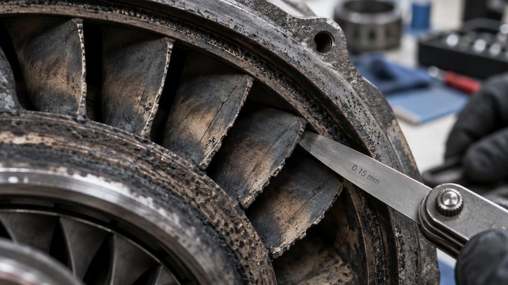
You’ll start the nozzle ring and vane check by measuring vane angle and clearances against OEM limits, since small deviations change turbine flow and loading. Next, you’ll remove carbon from the flow path with approved methods, so you don’t gouge vanes or shrouds. Wear gloves and eye protection throughout, and record every measurement before and after cleaning.
Vane Angle and Clearance Measurement
Because vane angle and clearance control gas flow, measure both before you approve a nozzle ring for reuse. Use calibrated gauges, and compare every reading with the OEM overhaul limits. Record each value against the locomotive’s service history.
| Check | Method and action |
|---|---|
| Vane angle | Measure each vane with an angle gauge; reject out-of-limit vanes |
| Ring clearance | Take feeler-gauge readings at several points around the ring |
| Shroud wear | Caliper the shroud; reject rubbing, thinning, or distortion |
| Fasteners | Verify fastener torque and thread condition; replace worn hardware |
Don’t reuse fasteners that fail inspection. Check fastener torque with a calibrated wrench, and inspect thread condition under good light. Reject bolts with stretched, galled, or damaged threads. Wear cut-resistant gloves, and support the ring securely while you measure.
Carbon and Flow Path Cleaning
Once you’ve confirmed vane angle and clearance, clean the flow path before you approve the nozzle ring. Wear safety glasses, a respirator, and nitrile gloves, because carbon and soot dust irritate lungs and skin.
Soften deposits with an approved solvent, then remove them with plastic scrapers and soft nylon brushes. Don’t use wire brushes or grit blasting, because they erode vane surfaces and alter airfoil geometry.
Check the compressor inlet and oil drain passages for lubrication contamination, since oil accelerates carbon formation.
Next, verify every passage is open. Pass a light through each nozzle opening, and confirm you see no shadowing. Then run a low-pressure air test and watch for uneven flow. Record the results, and photograph the cleaned passages for the overhaul file.
EMD 710 turbocharger inspection: NDT and Dimensional Verification
You’ve cleaned the parts and recorded visual findings, so now you need to confirm what the eye can’t see. Use approved NDT methods, such as magnetic particle or dye penetrant testing, on housing welds and critical surfaces, and judge indications against OEM limits. Then measure runout, fit-up, and sealing surfaces, because a part that passes visual checks can still leak or misalign once it’s installed on the locomotive.
EMD 710 turbocharger inspection: NDT Methods and Limits
During EMD 710 turbocharger inspection, nondestructive testing (NDT) exposes defects that visual checks miss on cleaned, tagged components. Use dye penetrant testing on turbine housing castings to reveal surface-breaking cracks, porosity, and weld defects. Apply magnetic particle testing to ferrous flanges, bolt holes, and nozzle ring mounting areas. Add eddy current or ultrasonic checks when you need to confirm wall thickness or subsurface indications.
Only qualified inspectors should perform and interpret these tests, per your shop’s certification program. Judge every indication against OEM acceptance limits, and reject linear cracks that exceed them. Record results by serial number to support root cause analysis and spot failure trends. These records let you adjust the overhaul interval and strengthen preventive maintenance planning. Don’t skip chemical handling rules.
Runout and Sealing Surface Checks
After NDT clears the turbine housing and nozzle ring, you’re ready to verify runout, fit-up, and sealing surfaces before assembly. Mount each component on calibrated fixtures and use dial indicators against OEM limits. Wear gloves and secure heavy housings with rated lifting gear.
- Runout: Rotate the assembly and record total indicator readings at each datum.
- Fit-up: Trial-assemble flanges, dowels, and bolt holes to confirm alignment without forcing.
- Sealing surfaces: Check flatness with a straightedge and feeler gauges, then inspect for pitting or fretting.
- Records: Enter every out-of-limit reading into nonconformance logging immediately.
Compare current readings with prior overhaul data. Dimensional trend analysis shows whether distortion is stable or progressing. That insight supports your repair-versus-replace decision. Reject any surface that can’t meet limits after machining.
In-service locomotive overhaul acceptance criteria: Documentation and Procurement
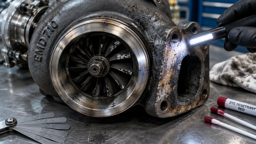
You’ve measured, tested, and documented every turbine housing and nozzle component, so now you need clear criteria to decide what returns to service. Set acceptance limits from OEM overhaul specifications, and reject any part that exceeds them, because a marginal component can fail between overhauls. Tie each decision to supplier records, part numbers, and repair history so procurement can trace every part you approve.
Acceptance Criteria and Rejection Triggers
Because an EMD 710 turbocharger runs at high speed and temperature, you can’t accept a housing or nozzle component on judgment alone. Apply written OEM limits and your locomotive’s overhaul record to every decision. Accept a component only when every measurement, NDT result, and sealing surface falls within limits. Reject the part when you find any of these triggers:
- Cracks in housing walls, flanges, welds, or vane roots that NDT reveals.
- Distortion that prevents alignment, fit-up, or flat sealing surfaces.
- Wear, erosion, or vane angle beyond OEM limits.
- Unsafe repairs, undocumented welds, or unverified replacement part numbers.
Complete Leakage Testing on sealing joints before approval; any seepage means rejection. Lubrication Verification confirms clear oil passages, and you can’t release any unit that fails it.
Procurement Traceability and Records
Passing every measurement and NDT check only matters if your records can prove it. Match each turbine housing, nozzle ring, and vane part number to the EMD drawing revision and your purchase order. Complete supplier certification validation before you accept any replacement part. Confirm material certificates, dimensional reports, and NDT results are traceable to the heat or lot number.
Next, perform repair history reconciliation. Compare the locomotive’s overhaul records, prior weld repairs, and supplier work orders for gaps. Flag any undocumented repair, and don’t release that component until you’ve resolved it.
Store the following in each component file:
- Photos of as-received and final conditions
- Measurement sheets with tool calibration IDs
- Final disposition: accept, repair, or scrap
Retain records per your locomotive overhaul acceptance criteria.
Frequently Asked Questions
How Should Technicians Safely Lift and Handle EMD 710 Turbocharger Housings in Locomotive Shops?
Picture a technician who rigs a turbine housing with one sling on a single lug. The housing swings, and a hand gets pinned. Prevent that with ergonomic lifting: you’ll weigh the housing, use rated slings, and attach only to designated lifting points. Complete hoist training before you operate an overhead crane. Wear gloves and safety boots, keep people clear, and lower the housing onto padded cribbing to protect mating surfaces.
What Protective Equipment Is Recommended When Removing Carbon Deposits From Locomotive Turbocharger Components?
You’ll need respiratory protection, eye protection, hand protection, and body protection when you’re removing carbon from locomotive turbocharger components. Wear a fitted P100 or equivalent respirator, because carbon dust and old deposits can contain fine particulates. Choose sealed goggles or a full face shield to block flying debris and solvent splash. Add chemical-resistant gloves, long sleeves, and hearing protection if you’re using grit blasting. Check your safety data sheets first.
What Operating Conditions Cause Carbon Buildup in EMD 710 Turbocharger Nozzle Passages?
Extended idling, light-load running, and frequent cold starts cause carbon buildup in your nozzle passages. Worn injectors, restricted air filters, and oil carryover worsen it by enriching combustion. During Leak Inspection, you’ll check for exhaust and oil leaks that signal these conditions. Your Vibration Monitoring data can reveal imbalance from deposits, so you shouldn’t ignore rising trends. Wear nitrile gloves, a respirator, and eye protection whenever you’re removing those deposits.
How Should Rejected Turbocharger Components Be Segregated and Stored After Locomotive Overhaul Inspection?
Like a medieval armorer scanning barcodes, you’ll segregate components immediately after rejection. Tag each part with its part number, locomotive number, and rejection reason. Move them to labeled storage, away from serviceable stock. Use red-tagged, lockable cages so nobody reinstalls them accidentally. Wear gloves when you lift heavy turbine housings, and use rated hoists. Record every item in your locomotive overhaul report, with dated photos, until you’ve reached final disposition.
When Does Repairing a Turbine Housing Make More Sense Than Replacing It?
Repair makes sense when damage stays localized and the casting still meets OEM limits. You’d choose weld repair for isolated cracks away from flanges, with sound base metal. Complete material inspection, including NDT, to confirm the casting isn’t corroded or heat-damaged. Replace the housing if you find distortion, widespread cracking, or sealing surfaces you can’t restore. Wear gloves and ventilation during grinding and welding. Document every decision for overhaul records.