
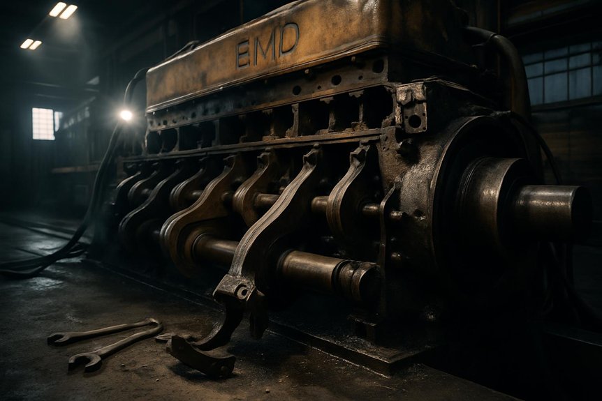
EMD locomotive rods cause engine failures when you let fatigue, fretting, oil-film loss, imbalance, or poor assembly distort the load path. Cyclic firing loads crack serrated joints, fillets, tool marks, and fretted faces before visible deformation appears. Oil starvation or coked crankpin galleries can wipe bearings, seize the crankpin, and overload the rod. Uprated horsepower, mismatched weights, and skipped alignment checks raise bending stress. Next, you’ll see how each failure mode leaves clear diagnostic evidence.
Why EMD Locomotive Rods Cause Engine Failures?
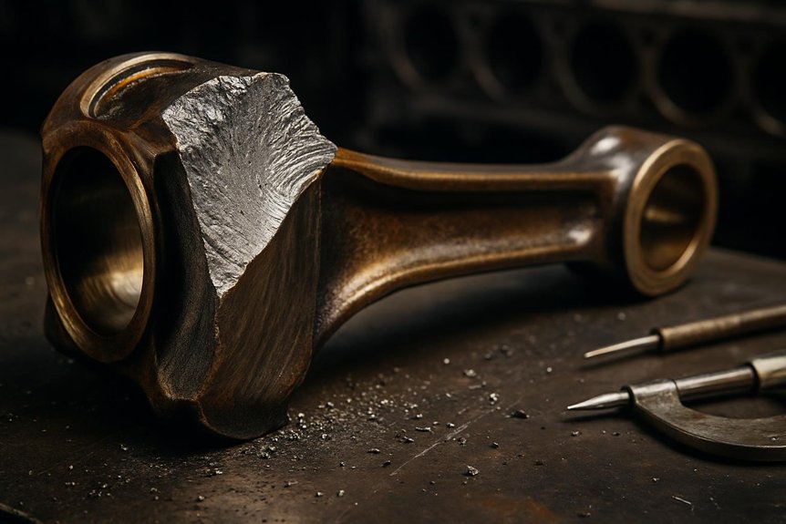
The primary failure stems from excessive bending stress on EMD connecting rods. These rods endure immense dynamic loads during service. Microscopic cracks often initiate at stress concentration points. These flaws propagate quickly under high-cycle fatigue. The rod’s design was intended for lower horsepower. Modern uprated engines push components beyond original limits. This creates a destructive failure pattern.
Poor lubrication also accelerates connecting rod failures. Oil starvation occurs at the crankpin bearing interface. This condition causes localized overheating and metal transfer. The degraded surface then acts as a stress riser. Metallurgical analysis frequently reveals wiping and severe scoring. Such damage makes the rod structurally vulnerable to catastrophic fracture. Early detection during overhauls is absolutely critical.
Material contamination introduces another significant risk factor. Hard particles in lubricating oil embed in the soft bearing overlay. These particles score the rod’s precision-machined surface. The resulting stress concentration triggers premature fatigue. Stringent oil cleanliness standards effectively mitigate this risk. However, older locomotive fleets often neglect these crucial filtration protocols.
Key Takeaways
- High-cycle fatigue at articulated or serrated joints can initiate cracks under repeated firing-load reversals before visible deformation appears.
- Surface discontinuities such as tool marks, nicks, and sharp transitions create stress risers that concentrate bending and combustion loads.
- Fretting, carbon contamination, and uneven serration contact weaken rod joints, reduce clamping integrity, and shift loads into damaging bending stresses.
- Crankpin bearing seizure from oil starvation, coked galleries, or poor filtration can collapse oil film and rapidly distress the rod.
- Uprated horsepower, imbalance, or incorrect overhaul practices can exceed original rod fatigue limits and accelerate bore, fillet, and bearing failures.
The Metallurgical Roots of EMD Connecting Rod Fractures
You often trace EMD locomotive rod failures to high-cycle fatigue starting at articulated joints under repeated combustion loading. You’ll see surface discontinuities act as stress risers, especially after bearing distress, scoring, or improper overhaul handling. You can confirm material contamination and fretting wear through oil analysis, magnetic particle inspection, and fracture-surface evaluation.
High-Cycle Fatigue in Articulated Joints
Often, EMD locomotive rod failures begin at the articulated or serrated joint, where cyclic load reversal concentrates stress. In V-type EMD power assemblies, you’re dealing with alternating compression and tension on every firing cycle. At high RPM, those reversals create high-cycle fatigue before visible deformation appears.
You diagnose this risk by treating the joint as a load-transfer interface, not just a fastened connection. Any loss of clamping force, fretting witness marks, or uneven serration contact changes how bending loads pass through the rod. That shift raises local tensile stress and accelerates crack initiation.
For reliable diesel engine connecting rod failure analysis, you should correlate fracture origin, beach marks, and service hours. During locomotive power assembly overhaul procedures, inspect articulated joints carefully before reusing rods in uprated service.
The Stress Riser Effect of Surface Discontinuities
After joint fatigue, surface condition becomes the next diagnostic focus in EMD locomotive rod failures. You inspect the rod beam because machining marks or handling nicks interrupt surface grain flow. Under combustion loading, each discontinuity concentrates bending stress and starts micro-cracking.
| Surface finding | Diagnostic meaning |
|---|---|
| Deep tool marks | Elevated notch stress |
| Handling nick | Impact-origin crack site |
| Sharp edge transition | Poor load distribution |
| Polishing break | Prior contact damage |
In diesel engine connecting rod failure analysis, you don’t treat these marks as cosmetic. You map their location against fracture origin, MPI indications, and overload history. If a flaw sits on the tensile side, crack growth accelerates with every duty cycle. During locomotive power assembly overhaul procedures, reject rods with sharp discontinuities before service.
Material Contamination and Fretting Wear
When hard carbon enters the rod joint, vibration turns contamination into a metallurgical failure driver. You’ll see particles embed at mating surfaces, then cut micro-grooves during load reversal. That fretting weakens mechanical interlock integrity and increases bending stress across the rod bore.
- Look for black oxide debris near serrations.
- Check bearing backs for polished slip marks.
- Compare oil carbon trends with wear metals.
- Inspect cap registers during locomotive power assembly overhaul procedures.
- Treat fretting as an early EMD locomotive rod failures warning.
In diesel engine connecting rod failure analysis, you shouldn’t isolate contamination from lubrication quality. Dirty oil accelerates overlay damage, crankpin scoring, and EMD 710 crankpin bearing failure. When Mikura International reviews worn rods, we link debris paths to contact loss, fatigue initiation, and fracture risk.
The Destructive Cascade of Crankpin Bearing Seizure
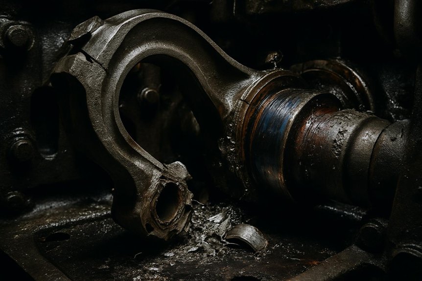
You’ll often trace EMD locomotive rod failures to oil starvation at the big-end crankpin interface. Once lubrication collapses, heat rises fast, smearing the Babbitt overlay and exposing the bearing to seizure. If you don’t stop the cascade, extreme heat distorts geometry and turns bearing distress into rod failure.
Oil Starvation at the Big-End Interface
At the big-end interface, EMD locomotive rod failures often begin with a lost oil film. When coked lube oil clogs crankpin galleries, you lose hydrodynamic separation instantly. Combustion force then drives direct metal contact across the bearing surface.
- You’ll see falling oil pressure trends before seizure.
- Find dark coke deposits inside crankpin passages.
- You’ll measure abnormal bearing clearance during teardown.
- Link scored journals to oil starvation, not overload alone.
- You’ll tighten locomotive power assembly overhaul procedures after inspection.
This failure path matters because bearing distress becomes rod distress. Once lubrication collapses, the big-end bore sees uneven loading and sharp stress concentration. In EMD 710 crankpin bearing failure analysis, you must connect oil chemistry, filtration, and gallery cleanliness before approving reuse.
Thermal Runaway and Smearing of Babbitt Overlay
As cooling oil flow collapses, crankpin bearing temperature rises beyond the Babbitt overlay’s melting range. You then see overlay liquefaction, wiping, and smeared metal across the loaded arc. That soft metal can promote liquid metal embrittlement, weakening the bearing surface under cyclic firing loads. In EMD locomotive rod failures, this is the seizure cascade you must catch early.
| Diagnostic clue | Failure mechanism | Your action |
|---|---|---|
| Dull gray smear | Babbitt wiping | Inspect oil delivery |
| Tin-rich streaks | Liquid overlay transfer | Sample bearing debris |
| Rapid heat tint | Lubrication collapse | Stop and investigate |
You shouldn’t treat this as cosmetic scoring. In EMD 710 crankpin bearing failure, smeared overlay raises friction, accelerates heat, and destroys oil film stability before rod fracture begins during service.
Geometric Distortion Under Extreme Heat
When a crankpin bearing seizes, the rod eye doesn’t heat uniformly. You get steep thermal gradients across the bore. Hot zones expand first, then quench rapidly as oil flow collapses and metal contacts metal.
- You’ll see bore ovality exceed overhaul limits.
- Lose bearing crush and interference fit.
- You’ll find localized bluing near the loaded arc.
- Measure cap shift after bolt release.
- You’ll link distortion to EMD locomotive rod failures.
This geometry change matters because the bearing shell can’t stay locked in position. Once crush relaxes, micro-movement starts. That fretting damages the housing bore and accelerates EMD 710 crankpin bearing failure. During diesel engine connecting rod failure analysis, you should verify roundness, taper, and cap alignment before reuse in locomotive power assembly overhaul procedures.
Why Increased Horsepower Upgrades Shorten Rod Life
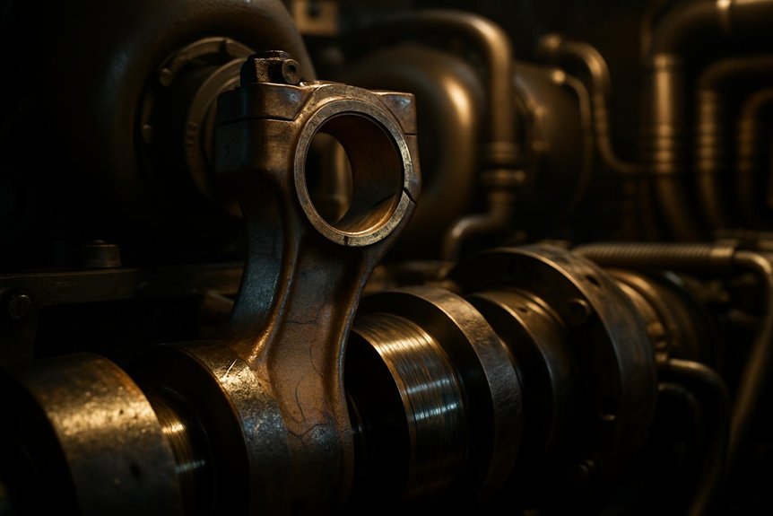
When you uprate an EMD engine, you can push rods beyond their original dynamic loading envelope. If balance weights don’t match the new firing loads, secondary imbalance raises bending stress and accelerates EMD locomotive rod failures. High-output duty also demands lubrication capacity that matches bearing heat, oil film strength, and crankpin load.
Exceeding the Original Dynamic Loading Envelope
Although horsepower upgrades can improve locomotive output, they can also push EMD rods beyond their original dynamic loading envelope. When you raise turbocharger boost, you raise peak firing pressure. That pressure increases rod bending moment past original EMD fatigue criteria.
Watch these diagnostic indicators during diesel engine connecting rod failure analysis:
- Higher cylinder pressure history after uprate calibration
- Ovality growth at the crankpin bore
- Fretting near rod serrations or parting faces
- Early signs of EMD 710 crankpin bearing failure
- Fatigue cracks starting at machined fillets
You’re no longer assessing static strength alone. You’re evaluating repeated high-cycle stress. In locomotive power assembly overhaul procedures, measure bore geometry, verify hardness, and inspect fillets carefully. Mikura International helps you match rod condition to actual duty, reducing EMD locomotive rod failures.
Incorrect Balance Weights and Secondary Imbalance
Higher firing pressure isn’t the only load path that shortens rod life after horsepower upgrades. You also need to verify piston and rod assembly balance during locomotive power assembly overhaul procedures. If overhaul sets leave the shop with mismatched weights, the rotating and reciprocating masses no longer cancel correctly.
That imbalance creates secondary vibration at operating speed. In an uprated EMD engine, those forces can drive bending resonance through the rod column. You may then see fretting, cap movement, uneven bearing crush, or early EMD 710 crankpin bearing failure. These clues belong in any diesel engine connecting rod failure analysis.
For EMD locomotive rod failures, don’t treat balance as paperwork. Match component weights, document tolerances, and reject mixed sets that shift dynamic loads beyond the original design margin.
Lubrication Mismatch in High-Output Engines
Under high-output duty, EMD locomotive rod failures often trace back to lubrication systems sized for earlier horsepower ratings. You raise cylinder pressure, piston temperature, and bearing load, but the legacy oil pump may not hold flow margin. Critical spray nozzles aimed at the rod and piston crown then see reduced delivery.
- You’ll see rising oil temperature before visible distress.
- Find bearing overlay wiping at the crankpin.
- You’ll detect copper, lead, and tin in oil analysis.
- Confirm nozzle restriction during power assembly overhaul procedures.
- You’ll link scoring to EMD 710 crankpin bearing failure.
That mismatch starves the crankpin interface, creates localized heat, and transfers metal. In diesel engine connecting rod failure analysis, this surface damage becomes a fatigue starter. Mikura International recommends verifying pump capacity before uprating horsepower.
Maintenance Blind Spots That Invite Catastrophic Events
You invite EMD locomotive rod failures when you stretch NDT intervals beyond fatigue-crack growth realities and increase crankpin bearing and scallop joint risk when you don’t verify torque, alignment, and mating surface condition. You miss early failure signals when you ignore oil analysis trends showing wear metals, contamination, or lubricant breakdown.
Inadequate Non-Destructive Testing (NDT) Intervals
Too often, inadequate NDT intervals let early EMD locomotive rod failures develop unnoticed. You may finish an overhaul with acceptable dimensions, yet miss subsurface fatigue. Magnetic particle inspection matters because serrated fork and blade rod regions concentrate bending stress.
- You expose cracks before they link into overload fractures.
- Verify suspect rods after EMD 710 crankpin bearing failure events.
- You correlate indications with oil debris and diesel engine connecting rod failure analysis.
- Tighten locomotive power assembly overhaul procedures for aging fleets.
- You prevent questionable rods from returning to high-horsepower service.
When you stretch inspection intervals, you lose the best diagnostic window. Cracks grow between shop visits, especially after lubrication distress or contamination. At Mikura International, we recommend disciplined MPI timing because hidden indications quickly become catastrophic rod separation.
Improper Torque and Scallop Joint Assembly
Even with disciplined NDT, improper torque and scallop joint assembly can initiate EMD locomotive rod failures after overhaul. You can pass inspection, then lose alignment during locomotive power assembly overhaul procedures. Inaccurate torque or worn dowels shifts the rod cap, creating an asymmetric load path. That distortion overloads one bearing edge and damages the crankpin surface.
| Assembly error | Diagnostic clue | Failure mechanism |
|---|---|---|
| Low torque | Cap fretting | Joint slip |
| High torque | Bolt stretch | Clamp loss |
| Worn dowels | Offset witness marks | Bore misalignment |
| Dirty scallop joint | Uneven seating | Edge loading |
You should verify calibrated tooling, dowel fit, and scallop cleanliness before closure. In diesel engine connecting rod failure analysis, these details separate stable service from EMD 710 crankpin bearing failure. Mikura International treats assembly geometry as a failure-control variable.
Ignoring Early Warning Signs in Oil Analysis
When oil analysis starts showing rising tin and lead PPM, your EMD engine is often warning you early. You’re seeing bearing overlay distress before EMD locomotive rod failures become visible damage. Ignore that trend, and an EMD 710 crankpin bearing failure can progress into heat, wiping, seizure, and rod fracture.
- Track tin and lead shifts between sampling intervals.
- Compare PPM increases against oil hours and load cycles.
- Flag abnormal bearing metal before the next road failure.
- Plan bearing replacement during a scheduled pit stop.
- Link oil data to locomotive power assembly overhaul procedures.
You can’t treat spectrometric reports as paperwork. They’re diesel engine connecting rod failure analysis in motion. At Mikura International, we’ve seen small wear-metal trends protect crankshafts, rods, budgets, and service reliability.
Proven Strategies to Eliminate Premature Rod Failures
You prevent EMD locomotive rod failures by controlling parts specification, oil delivery, and alignment accuracy. You can’t accept aftermarket rods, bearings, or bolts unless they meet proven metallurgy, geometry, load requirements and reduce crankpin bearing distress with lubrication upgrades and laser-aligned reassembly that protects rod bore geometry.
Strict Compliance with Aftermarket Parts Specifications
Validate every aftermarket connecting rod against EMD-specific mechanical and dimensional requirements before installation. You reduce EMD locomotive rod failures when you verify stiffness, grain flow, and machining accuracy for heavily loaded 2-stroke engines. Don’t assume catalog interchangeability equals fatigue compatibility.
- Confirm alloy chemistry and heat-treatment records before release.
- Inspect grain flow alignment through the shank and big-end transition.
- Measure bore geometry, cap fit, and side clearance against EMD limits.
- Require magnetic particle inspection for laps, seams, and quench cracks.
- Document traceability for each rod used during power assembly overhaul.
If stiffness deviates, crankpin loading changes. That can accelerate bearing edge loading and fatigue initiation. In diesel engine connecting rod failure analysis, aftermarket variance often explains repeat fractures after otherwise correct overhaul procedures in locomotive service.
Enhanced Lubrication System Upgrades for Tier-Level Emissions
A lubrication upgrade directly reduces EMD locomotive rod failures on Tier-level emissions fleets. You’re managing higher heat rejection, longer idle cycles, and tighter emissions calibration. These conditions thin oil films at the crankpin bearing and accelerate EMD 710 crankpin bearing failure.
Install high-efficiency bypass filtration to remove fine abrasive particles before they embed in bearing overlay. This supports diesel engine connecting rod failure analysis by linking silicon, iron, and lead trends to active wear. Add high-capacity cooling nozzles to control piston undercrown and rod bearing temperatures. Stable oil viscosity protects hydrodynamic film strength under peak firing loads.
During locomotive power assembly overhaul procedures, verify nozzle flow, filter differential pressure, and oil gallery cleanliness. Mikura International helps you match upgraded lubrication parts to EMD duty cycles, without overstating what hardware alone can prevent.
Precision Reassembly Through Laser Alignment
Measure crankshaft deflection and rod parallelism with laser alignment before final torque. You’ll catch angular error that feeler checks miss during locomotive power assembly overhaul procedures. Misalignment loads one bearing edge, disrupts oil film, and accelerates EMD 710 crankpin bearing failure.
- Verify crankshaft deflection at specified throw positions.
- Confirm rod parallelism across both bearing bores.
- Detect bolt binding before stretch readings become misleading.
- Set uniform bearing oil clearance under real assembly geometry.
- Record laser readings for diesel engine connecting rod failure analysis.
If you skip this step, you can assemble stress into the engine. That stress becomes heat, wiping, and fatigue cracking under load. For EMD locomotive rod failures, precision alignment turns reassembly into prevention, not guesswork. Mikura International supports this process with quality rod and bearing components.
Frequently Asked Questions
What Records Help Trace Repeat EMD Locomotive Rod Failures?
You trace repeat EMD locomotive rod failures with overhaul records, rod serial numbers, crankpin bearing clearances, torque logs, oil analysis reports, and MPI inspection results. You should also track power assembly hours, lube pressure trends, filter debris findings, and eco-mode duty cycles. These records link EMD locomotive rod failures to fatigue, lubrication loss, contamination, or assembly error. Don’t ignore supplier traceability and metallurgy reports when patterns repeat across units.
Can Rod Failures Indicate Deeper Crankshaft Alignment Issues?
Yes, rod failures can signal deeper crankshaft alignment issues. You should investigate repeat failures on the same crankpin, uneven bearing wear, edge loading, fretting, or abnormal main bearing temperatures. Misalignment changes oil film geometry and increases bending stress through the rod beam. Don’t treat the rod alone as the root cause. Check crankshaft runout, main bore alignment, bearing crush, and saddle condition during overhaul before releasing the locomotive back to service.
How Should Procurement Teams Qualify Replacement EMD Connecting Rods?
You should qualify replacement EMD connecting rods through documented metallurgy, dimensional inspection, and service traceability. Don’t rely on price alone. Verify material certification, heat treatment records, crankpin bore geometry, serration integrity, and magnetic particle inspection results. Match rods to locomotive duty cycle, horsepower rating, and overhaul procedures. Review oil-related failure history, bearing seizure evidence, and fatigue locations.
When Should Rods Be Retired Despite Passing Inspection?
Retire rods when history outweighs today’s clean report. Like a rail bridge with hidden fatigue, a rod can pass MPI yet carry risk. You should remove it after overspeed, bearing seizure, crankpin heat distress, repeated high metal oil trends, known lube starvation, or uncertain service hours. Don’t reuse rods with fretting, bore distortion, prior straightening, or nontraceable pedigree. In EMD locomotive rod failures, inspection data must yield to operating evidence.
How Do Storage Conditions Affect Spare Connecting Rod Reliability?
Storage conditions directly affect spare connecting rod reliability by controlling corrosion, fretting, and dimensional stability. You should keep rods dry, sealed, and coated with approved preservative oil. If humidity attacks machined bores or serrations, you’ll create stress risers that MPI may miss. Don’t stack rods bare or mix bearing shells loosely. Before installation, verify bore roundness, surface condition, and traceability. Poor storage can turn serviceable spares into premature failure risks.