

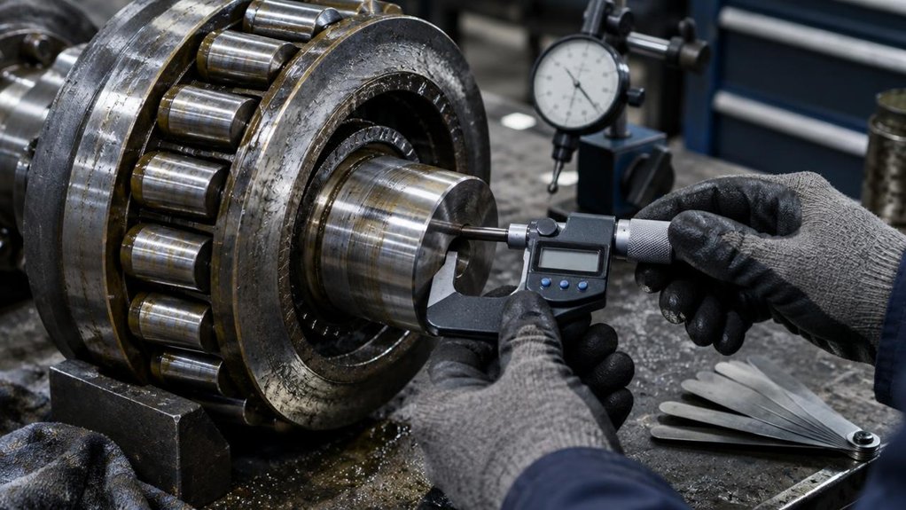
Locomotive maintenance teams often struggle to separate real bearing wear from measurement error.
Inaccurate readings lead to missed failures, unplanned downtime, and costly crankshaft damage.
Wrong clearance numbers also cause premature shell replacement.
Accurate, repeatable measurement prevents these problems before they reach the engine.
The tips below show how to measure consistently and reliably.
Common pain points:
- Clearance readings change from one inspection to the next.
- Heat from recent operation distorts measurements.
- Dirty journals and anvils produce false wear readings.
- Teams apply the wrong wear limit to a journal.
- Crown and parting-line wear are often misread or ignored.
- Inspection records are incomplete, so wear trends go unnoticed.
- Shells are replaced too early or too late.
| Inspection Checkpoint | What to Verify | Why It Matters |
|---|---|---|
| Component temperature | Cap, axle, and frame are at ambient temperature | Heat closes clearance and hides metal loss |
| Journal and anvil condition | Surfaces are clean and free of oil, carbon, and debris | Contamination causes inaccurate gauge readings |
| Main bearing clearance | Measured in place using the correct method | Confirms the actual running clearance |
| Crown wear | Uniform wear pattern across the shell | Indicates load distribution or alignment issues |
| Parting-line wear | Edge wear at the shell split line | Points to housing fit or installation problems |
| Model-specific limit | Matched to the correct EMD published maximum | Prevents using the wrong replacement criteria |
| Inspection record | Readings, dates, and tag numbers logged | Enables trend analysis and early warning |
Tip 1: Let Components Cool to Ambient Temperature
Wait until the cap, axle, and frame reach ambient temperature.
Heat closes clearance.
Warm components hide real metal loss.
Measure only after everything has stabilized.
Tip 2: Clean Journals and Anvils Thoroughly
Wipe the journals and anvils clean before measuring.
Remove oil, carbon, and debris.
Contamination skews gauge readings.
Clean surfaces give repeatable results.
Tip 3: Gauge Main Clearance In Place
Measure main bearing clearance without removing the shell from the housing.
Use the approved method for the engine model.
Record readings at the specified positions each time.
Tip 4: Read Crown and Parting-Line Wear
Inspect the crown of the shell for uniform wear.
Check the parting line for edge wear.
Crown wear often signals load or alignment issues.
Parting-line wear often points to housing fit problems.
Tip 5: Match Each Journal to the Correct EMD Limit
Confirm the engine model, bearing size, and current service data before comparing readings.
Apply the published EMD maximum for that specific journal.
Do not rely on generic or outdated limits.
Tip 6: Log Every Inspection
Record every clearance reading, date, and tag number.
Include oil analysis results and housing observations.
Consistent logs reveal wear trends before failure occurs.
Tip 7: Replace the Shell at the Published Maximum
Replace the shell once clearance reaches the published maximum.
Inspect the housing for damage before reinstalling.
Stay consistent with inspections, so oil trends and housing checks remain reliable.
Mikura International supplies genuine locomotive engine parts, including EMD main bearing shells, for verified replacement needs.
Key Takeaways
- Measure traction-motor and support bearings only after they cool fully to ambient temperature.
- Wipe journals, cap faces, and gauge anvils clean before seating any measuring tool.
- Gauge clearance in place using the builder’s Plastigage, lead-wire, or dial-indicator method.
- Record crown wear and the thinner parting-line wall thickness; replace shells at the builder’s crown limit.
- Compare each reading with the engine-specific EMD limit and confirm wear with oil-analysis trends.
Measure EMD Bearing Wear Only When Cold
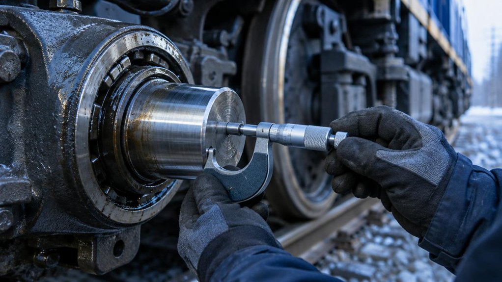
Because EMD traction-motor and support bearings expand as they heat, measure wear only after the locomotive cools to ambient temperature. Do not gauge a hot journal and treat the reading as final. Thermal growth closes clearances and shifts the housing. A warm reading understates wear. It can hide a bearing that is already out of limit.
Set cold measurement timing by the shop thermometer, not by how long the unit has sat. Wait until the bearing cap, the axle, and the motor frame match ambient air. If one component stays warmer, wait longer. Record the air temperature beside each reading. This lets the next inspector confirm the same condition.
Prevent measurement bias by comparing each reading with the last cold record. Do not compare against a hot check taken during the run. Do not torque, pry, or correct for unmeasured heat. If the locomotive ran recently, leave gauges boxed.
Clean Bearing Surfaces Before You Gauge
Before you seat the gauge, wipe the journal, the cap face, and both anvils until clean metal shows. Oil film, carbon, and lint change contact and shift your reading. Use a clean, lint-free rag and a light solvent approved for the locomotive bearing. Don’t leave any residue behind.
After you wipe, inspect the lubricant condition on the rag and in the oil groove. Dark grit, metal flakes, or a burnt smell means you stop and report the finding before you continue. Then verify bearing alignment by eye and by feel. The cap must sit square on the journal without a cocked edge or a lifted corner. A cocked cap loads one anvil and gives a false wear number.
Reclean any spot the rag missed. Seat the anvils only on dry, bright metal. If you don’t, grit under the contact pads stacks into the measurement. You end up chasing a number that isn’t real.
Gauge Main Bearing Clearance in Place
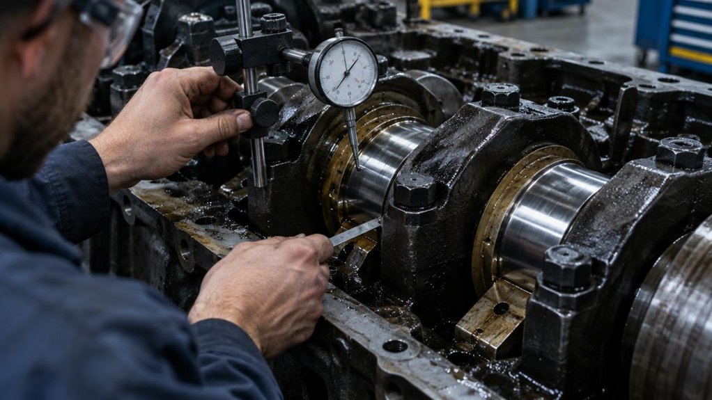
How do you gauge main bearing clearance in place on a locomotive engine? Start by confirming the locomotive builder’s inspection procedure. Avoid crankshaft removal unless the railroad’s maintenance procedure requires a full teardown. Select inspection tooling that matches the engine builder’s method. Choose Plastigage, calibrated lead wire, or a dial indicator on a rigid fixture. Clean the journal and bearing shell thoroughly before any measurement. Seat the gauge material or indicator tip only where the procedure allows.
Torque the main bearing cap to the specified sequence and value. Release the cap carefully, then read the crushed gauge width or indicator travel. Compare the reading against the specification chart for that bearing position. Match the comparison to the oil grade and temperature band listed in the procedure. Reject any reading outside the minimum or maximum clearance limits. Record the bearing position, tool ID, and torque value for each measurement. Consistent records allow the next inspection to repeat the same setup. Stop once installed clearance is confirmed, logged, and checked against the builder limit for that main bearing.
Mikura International offers locomotive engine bearing components and inspection tooling for railroad maintenance teams.
Read Bearing Wear at Crown and Parting Line
You read crown wear first because that point takes the highest load and shows the earliest loss of bearing material. Place the gauge at the crown, record the thickness, and compare it with the manufacturer’s limit before you accept the shell. Then check both parting lines for edge wear, fretting, and uneven crush so you don’t miss a shell that’s still thick at the crown but failing at the joints.
Crown Wear Reading
When you take a crown wear reading on a locomotive engine, measure the bearing shell at the crown and at the parting line. Compare the two thicknesses to quantify metal loss. Seat the shell on a flat reference plate first. Zero your digital dial gauge on an unworn area before you probe the crown. Hold the gauge perpendicular to the shell surface. Take three readings across the crown and record the lowest value. Subtract the crown thickness from the parting-line thickness to find wear. Do not average away a local thin spot. Log each result with engine hours so wear trends show whether loss is stable or accelerating. Replace the shell when crown wear reaches the locomotive builder’s limit. Recheck the readings if they disagree.
Parting Line Checks
Parting-line thickness sets the baseline for wear calculation. Check both locomotive bearing shell halves with the same gauge setup. Place each shell half on a certified flat plate. Measure wall thickness at both parting lines with one micrometer. Keep anvil force, temperature, and zero consistent for every point. Record the thinner parting-line value as the baseline. Subtract the lowest crown reading from that baseline to calculate wear. Do not average mismatched halves. When the two parting-line readings exceed the manufacturer’s spread, reject the shell. Order NDE inspection for the rejected shell. Open root cause analysis for crush loss, bore distortion, or embedded debris. Recheck the locomotive engine housing before reuse. This keeps your wear figure repeatable. Log the gauge serial number with every reading.
Compare Bearing Wear With EMD Limits
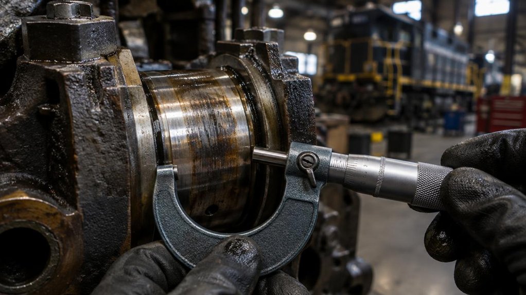
On locomotive engines, match each wear reading to the EMD limit for that position.
Use the bearing position, engine model, and service interval for every comparison.
Do not use one clearance for every journal.
Main, rod, and cam bearings follow separate charts.
A 645 limit does not apply to a 710 engine.
Select the table for the engine model and the service interval now in force.
Compare OEM and EMD tolerances before you scrap any shell.
OEM specifications often run tighter than EMD field limits.
A high OEM comparison can still pass the railroad limit.
Decide from the EMD figure.
Use the OEM gap only to judge how fast clearance is growing.
Interpret wear gauge trends on the same journal.
A sub-limit reading that climbs each time needs action sooner.
A steady reading near the cap can wait longer.
Replace any bearing that meets or exceeds the published EMD maximum.
Record Bearing Wear After Each Inspection
Log each bearing clearance right after you finish the inspection. Do not delay the entry until shift end. Delayed entries mix positions and reduce precision.
Record the clearance beside the bearing location, locomotive engine number, date, and your name. Use the same units every time. Consistent units keep comparisons valid.
Attach the reading to your visual inspection records before you leave the work area. Add brief notes on oil film, discoloration, and scoring. Keep these observations separate from the measured value.
You will rely on these figures for trend wear analysis after repeated inspections. Identify the gauge and its calibration date. Reviewers use this information to assess data quality.
If you repeat a questionable measurement, enter both results. Mark the accepted reading clearly. Retain measured precision without rounding.
Sign every line. Place the completed sheet where the next crew can retrieve it immediately. File the sheet before you leave today.
Schedule Replacement When Bearing Wear Exceeds Spec
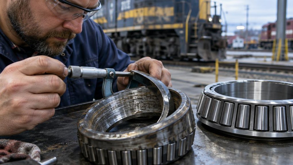
You’ve recorded each clearance with its location and date. Compare the accepted reading with the published wear limit before the locomotive returns to service.
If clearance exceeds the published specification, do not return the locomotive to service. Schedule replacement before the next assignment. Tag the axle so dispatch will not release it.
Complete a bearing housing inspection before you order parts. Check the bore for ovality, fretting, and heat tint. Confirm cap-bolt torque. Do not reuse a housing that fails those checks. Replace it with a qualified new spare from Mikura International.
Use oil analysis trending to confirm the reading. Rising iron or copper, with falling viscosity, shows the wear is not an isolated measurement error. When metals rise across two samples as clearance grows, move the replacement earlier.
Log the limit, the decision, and the shop that will fit the new bearing. This keeps the out-of-spec journal off the main line.
Frequently Asked Questions
What Tools Are Needed to Measure EMD Bearing Wear?
Line the gauge up with the scar so both readings coincide. Never trust a single number.
Measure EMD bearing wear with an outside micrometer, a dial bore gauge, and a feeler set.
Add ultrasonic testing when wall loss hides beneath the surface.
Run a boroscope inspection when you cannot pull the cap.
Record clearance, ovality, and heat tint before you release the locomotive engine.
How Often Should Railroad Engine Bearings Be Inspected?
Railroad engine bearings require inspection on a schedule set by the engine builder. Your railroad’s preventive maintenance program also defines these intervals. Actual operating conditions determine how often you should check them. Typical intervals range from daily visual checks of oil, temperature, and vibration. Scheduled teardowns occur at defined mileage or hour limits. Do not wait for failure to act. Tighten inspection intervals when you see rising heat, metal in the oil, or abnormal noise. Document every check result so that trends become visible over time. Mikura International supports locomotive maintenance teams with quality bearing components and technical guidance.
What Symptoms Indicate Excessive Railroad Engine Bearing Wear?
The writing is on the wall when excessive bearing wear appears in a locomotive engine. Early detection protects the engine, the train, and the crew.
Watch for common failure indicators and unusual vibration symptoms right away. Small changes often signal larger problems ahead.
Heat rise is one of the first warning signs. A bearing running hotter than normal points to lubrication loss or excessive friction.
Metallic noise deserves immediate attention. Grinding, whining, or knocking sounds often indicate that bearing surfaces are breaking down.
Discolored oil is another key indicator. Dark, milky, or glittery oil may carry metal particles from worn bearing surfaces.
Excess end play also signals trouble. Measure the axial movement of the crankshaft and compare it against manufacturer limits.
Do not ignore rumble, knock, or a harsher running feel. These symptoms often appear before bearing failure becomes visible.
Maintenance teams should measure clearances and log trends over time. Trend data reveals gradual wear that a single inspection might miss.
Remove the engine from service if measured clearances exceed approved limits. Continued operation can damage the crankshaft and surrounding components.
Shut the engine down before the journal seizes. A seized journal or failed axle under load can cause derailment and serious injury.
Mikura International recommends regular inspection schedules for locomotive engines. Consistent monitoring helps operators avoid costly unplanned failures.
Who Is Qualified to Measure EMD Engine Bearing Wear?
You rely on qualified personnel to measure EMD locomotive engine bearing wear. Qualified personnel include EMD-trained diesel technicians, certified railroad machinists, and OEM-authorized inspectors. These professionals know the engine model and the correct gauging method. General laborers should not handle this work. A documentation review must come first before anyone sets a micrometer. The review covers the maintenance manual, wear-limit tables, calibration records, and the work order. This step matches the procedure to the bearing. It also ensures every result is traceable.
Can Hot Bearings Be Measured After Cooling Completely?
A hot locomotive bearing gives a valid wear reading only after it cools completely. Testing confirms this principle holds, but only within clear limits. Technicians measure the axle journal only when it reaches ambient temperature. Time alone is not a reliable indicator of readiness. Cooling intervals are enforced so contraction finishes evenly across the journal.
Before logging any diameter, technicians verify caliper accuracy against a certified standard. The measured figures are then compared with the bearing’s baseline record. Any reading affected by residual heat is rejected and never logged. Mikura International recommends following this sequence on every locomotive bearing inspection. Disciplined measurement protects bearing life and supports dependable locomotive operation.