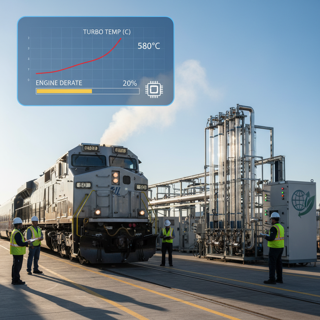
Choosing Cylinder Liners That Survive Australian Rail Conditions

Choosing Cylinder Liners That Survive Australian Rail Conditions

Picture this: a fully loaded ore train, ten thousand tonnes of cargo, grinding to a halt somewhere in the Pilbara because a single cylinder liner gave out. What follows is a cascade of expensive problems — emergency repairs, blown schedules, crew reshuffling, and a recovery locomotive dispatched at premium cost. After more than twenty years spent servicing EMD engines throughout Australia’s rail corridors, I’ve witnessed this scenario unfold repeatedly. The underlying cause is almost always identical: a cylinder liner never designed to cope with the environment it was thrown into.

Australia’s rail infrastructure spans more than 40,000 kilometres, crossing some of the most brutal terrain imaginable. Temperatures soaring past 45°C, fine red dust infiltrating every gap and gasket, and relentless heavy-haul schedules combine into a punishing gauntlet for engine parts. Cylinder liners — the removable sleeves lining each engine cylinder — absorb the brunt of this punishment.

These components guide piston movement, channel massive heat loads into the cooling system, and maintain the combustion seal. Premature wear, scoring, or cracking in a liner translates directly into lost compression, excessive oil burn, and ultimately, engine failure.

A failed liner can idle a locomotive at a cost of $50,000 daily. That figure covers lost freight revenue, emergency recovery, and rushed parts shipments to isolated depots — and it excludes the cascading damage to pistons, the engine block, and crankshaft bearings that often accompanies a liner seizure. For fleet managers, liner selection isn’t a minor procurement detail. It’s arguably the most consequential factor in engine reliability and lifespan.

So what separates a genuinely “good” liner from an inadequate one in Australian conditions? Three factors: the base metal composition, the surface finishing process, and manufacturing precision. Standard OEM liners — usually basic grey cast iron — were engineered for moderate climates. They perform adequately in Europe or North America, but under Australia’s extreme heat and dust loads, they degrade faster, warp more severely, and fail sooner than expected.

Superior aftermarket liners incorporate alloying elements like chromium, molybdenum, and nickel, then undergo treatments such as plateau honing or gas nitriding to produce a tougher, oil-holding bore surface. The payoff is a liner that resists scuffing, dissipates heat more effectively, and preserves ring seal integrity across thousands of additional operating hours.

Upgraded liners can add roughly 20% to overall engine life. This isn’t a sales pitch — it’s a pattern I’ve confirmed repeatedly through teardown analysis and oil sampling data across fleets operating in the Bowen Basin, Hunter Valley, and along the Nullarbor. The right liner choice, combined with proper fitting and sound upkeep, can push a 15,000-hour engine to 18,000 hours of service. Choose poorly, and a standard overhaul becomes a recurring headache.

Upgraded liners can add roughly 20% to overall engine life

This piece draws on decades of hands-on work with EMD 645 and 710 engines in Australian service conditions. It covers why factory-standard liners struggle locally, which material properties genuinely matter, and which five liner options deliver the strongest combination of durability, thermal performance, and cost-effectiveness. It also flags the installation errors that can ruin even top-tier components, plus the ongoing maintenance habits that keep liners performing. The objective is straightforward: help readers select a liner built for outback punishment, not merely one that fits.


Why Factory-Standard Liners Fall Short in Australia

Australian rail corridors subject engine components to stresses that manufacturer testing rarely simulates. Extreme heat, abrasive dust, and unforgiving heavy-haul cycles combine to accelerate liner degradation well beyond typical expectations. The outcome is a predictable pattern of early failure that maintenance teams nationwide recognize immediately.

Grasping why standard liners underperform in these conditions is essential before specifying replacements built to last. The sections below explore the specific environmental pressures involved and the warning signals indicating a liner is approaching failure.

Heat, Dust, and the Weight of Heavy Haul

A liner that holds up fine on a modest 2,000-tonne coastal run can fall apart within months hauling 5,000 tonnes of ore through Pilbara terrain. Failure doesn’t happen suddenly — it starts subtly with faint bore scoring, progresses to blow-by and oil consumption, and eventually culminates in piston seizure. The underlying issue is nearly always the same: the liner wasn’t engineered for the thermal and abrasive demands it now faces.

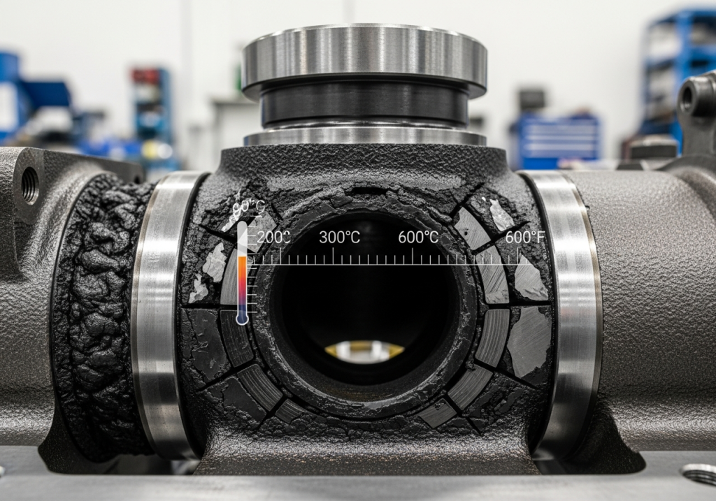
Outback temperatures frequently exceed 45°C. That number alone doesn’t capture the full picture. The real problem emerges from what happens inside the cylinder when the surrounding air is already blistering. Combustion temperatures rise further, the cooling system has reduced capacity to dissipate heat, and the liner’s flange region expands thermally in ways that distort its shape.

A standard liner doesn’t absorb this heat evenly. The consequence is a bore that loses its perfect roundness under operational load, concentrating wear specifically on the piston’s thrust side.

Dust compounds the problem significantly. Fine outback red dust isn’t ordinary dirt — it’s a silica-rich abrasive substance measuring between 5 and 75 microns. It bypasses air filtration, blends into oil films, and lodges within the graphite structure of standard cast iron.

From that point forward, the liner effectively becomes an abrasive tool against itself. Each piston stroke drags embedded particles across the cylinder wall.

The resulting wear pattern resembles sandpaper damage — because functionally, that’s precisely what occurred.

“People don’t appreciate how much damage dust causes because it’s invisible inside the engine. I’ve extracted liners from Nullarbor-route locomotives that looked like they’d been deliberately roughened with coarse abrasive stone. That was purely airborne silica at work.”
— Senior Maintenance Engineer, Australian freight operator

Heavy-haul operating patterns make both issues worse. Typical Australian freight trains weigh between 3,000 and 6,000 tonnes, often running long distances without cooling breaks. That translates into hours of continuous high-load operation.

The liner gets no cooling reprieve, no relief from cylinder pressure, and no break from the abrasive contamination circulating within the oil. Standard OEM liners were built for different usage patterns — shorter distances, lighter loads, more frequent idle time.

These liners simply weren’t specified for this level of abuse.

Thermal stress, particulate contamination, and continuous high-load friction don’t operate independently — they reinforce one another. Heat warps the bore, creating clearance gaps that admit more dust into the wear zone, increasing friction, which generates additional heat.

It’s a self-reinforcing cycle that standard liners can’t escape. Breaking it requires selecting a liner with material composition and surface treatment purpose-built for these specific conditions.

Companies like Mikura International have structured their entire aftermarket liner offerings around addressing this exact failure pattern, because Australian operating conditions demand it.

Standard liners aren’t poorly made — they’re simply mismatched to the environment they’re being asked to endure. Once a locomotive operates in 45-degree heat, hauling dust-laden air and 5,000 tonnes of cargo, the assumptions built into a basic OEM liner’s design no longer apply.

That’s not a knock against factory equipment. It’s simply operational reality.

Warning Signs Your Engine Is Telling You Something

In 2023, a Pilbara iron-ore operator recorded a 17% spike in lubricating oil consumption across three EMD 710-powered locomotives within a single quarter. That was the initial red flag. By the time engineers opened the units for inspection, damage had already extended past the liners into piston ring lands and crankcase bearings.

Repair costs tripled. This is the outcome when early warning indicators get written off as “typical wear for an aging engine.”

A 15-20% rise in oil consumption signals more than a tuning quirk. It indicates combustion gases bypassing the rings and pressurizing the crankcase, forcing oil past seals and breather systems. A properly functioning EMD engine burns oil at a consistent, predictable rate between services. When that number climbs steadily across two or three fuel cycles, it means the liner walls have lost their oil-retention crosshatch pattern.

The rings can no longer perform their scraping function effectively. The engine is consuming itself from the inside.

Compression readings reveal a parallel story. A 10% compression drop across multiple cylinders points toward liner bore wear — not an isolated ring failure. Mechanics frequently investigate injector timing or valve adjustment first.

That’s the wrong direction entirely. Compression loss in an EMD engine typically means the seal between liner wall and rings has broken down.

The solution isn’t a tune-up — it’s a liner replacement.

Visual inspection remains the most economical diagnostic method available. Remove an inspection cover and look closely. Visible scoring on the liner surface — vertical grooves detectable with a fingernail — indicates abrasive particles have lodged in ring faces and are actively machining the bore.

This is silica dust damage made visible. Scoring typically concentrates near the liner’s top, where ring travel direction reverses.

Once these grooves develop, the liner can’t be salvaged. Honing won’t reverse this damage.

Crankcase blow-by provides another diagnostic clue. Remove the oil filler cap while the engine idles. A steady burst of hot gas against your hand indicates combustion pressure is escaping past the rings.

That gas introduces unburned fuel and soot particles into the oil supply. The oil thickens progressively. Additive packages deplete faster. Every downstream component suffers as a result. Blow-by isn’t exclusively a liner issue, but it’s almost always the primary contributing factor.

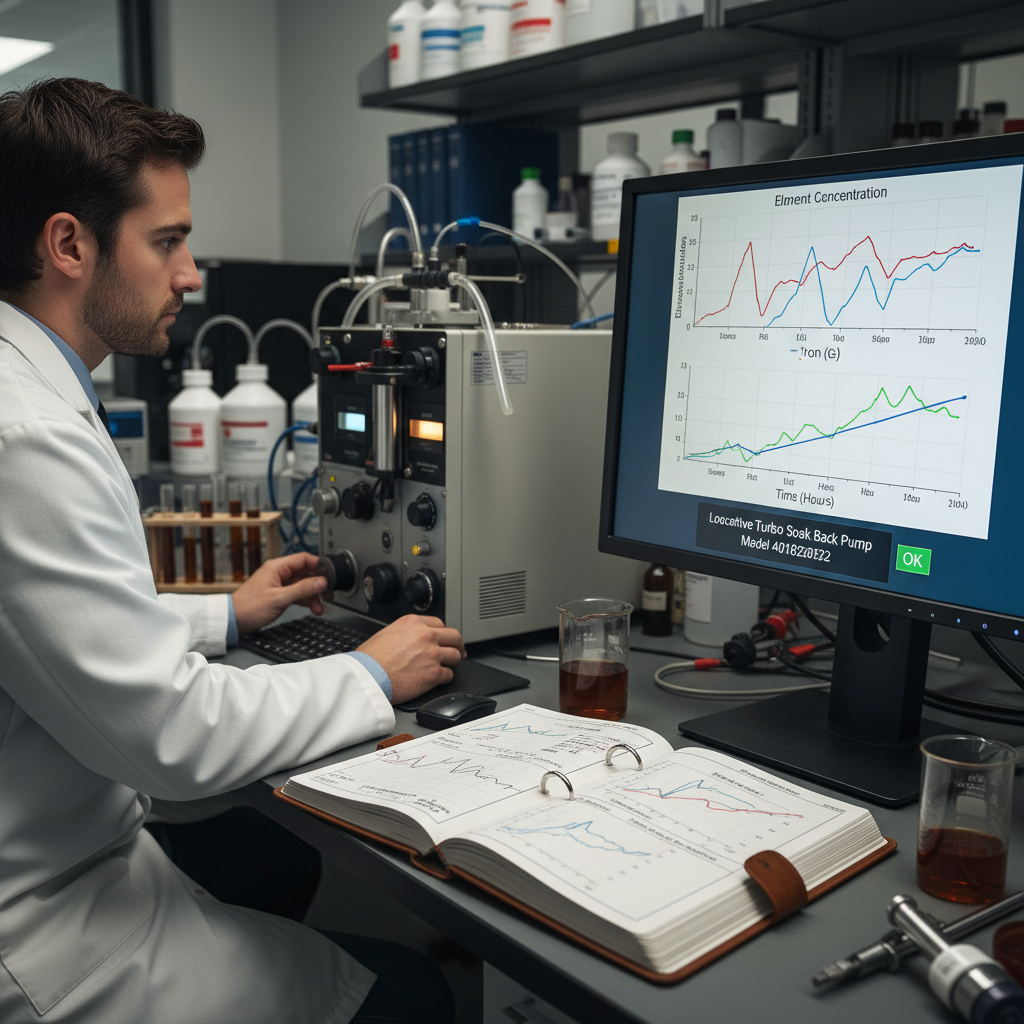
Laboratory oil analysis confirms the diagnosis. Rising metallic particle counts — specifically iron and chromium trending upward across three consecutive samples — verify liner and ring degradation. Iron originates from the liner body itself. Chromium comes from ring surfaces. Simultaneous spikes in both metals indicate the two surfaces are actively grinding against each other.

Laboratory reports will label this “abnormal wear metals.” That’s precisely the point where liner replacement remains cheaper than a complete power assembly rebuild.

These indicators rarely appear in isolation. Oil consumption climbs, compression drops, blow-by increases, and lab reports show elevated metal content. Collectively, this pattern points to one conclusion: liners are deteriorating faster than scheduled maintenance anticipated.

Environmental stressors are winning this battle. What operators need is a liner material engineered to resist scoring, maintain its crosshatch pattern longer, and dissipate heat more efficiently.

That’s fundamentally a materials science challenge, not a maintenance scheduling problem.


The Material Science Behind Superior Liners

The gap between a liner lasting 400,000 kilometres versus one failing at half that distance is frequently determined before the engine ever fires up. Metallurgy and surface engineering have advanced considerably beyond basic grey iron castings of previous generations. Leading manufacturers now employ alloy formulations and treatment processes that resist scuffing, corrosion, and thermal fatigue in ways older-generation liners simply couldn’t match. Understanding these material distinctions clarifies why premium liners justify higher price points through measurably extended service life in demanding locomotive applications.

The Material Science Behind Superior Liners

Advancing Beyond Basic Cast Iron

A conventional grey cast iron liner performs adequately in locomotives that never encounter extreme heat or abrasive contamination. The moment those conditions materialize, however, the base material becomes the limiting factor. This is why metallurgists introduce specific alloying elements to the base iron, fundamentally altering the metal’s microscopic behavior.

Chromium content boosts hardness by 25-30%. This isn’t promotional language — it’s a quantifiable shift in the metal’s resistance to deformation when abrasive particles scrape across the surface. Chromium generates hard carbide particles distributed throughout the iron matrix. These carbides function like microscopic speed bumps against silica dust, reducing the cutting action that would otherwise gouge the bore surface.

Molybdenum contributes differently. Molybdenum enhances tensile strength by approximately 15%, which matters more than commonly recognized. Liner wear isn’t purely friction-based — the material experiences constant pulling, stretching, and compression as the piston reverses direction at high velocity. Standard cast iron can develop micro-fractures under this repeated stress cycle.

Molybdenum helps the metal maintain structural integrity longer before these fractures emerge.

“The base iron establishes the foundation, but alloying elements determine whether a liner lasts 20,000 kilometres or 40,000. Chromium and molybdenum aren’t luxury additions — they represent the fundamental difference between survival and failure.”
— Dr. Alan Whitfield, Metallurgical Engineer, Rail Materials Research Group

Vanadium represents a third critical element. Vanadium carbide inclusions boost scuff resistance in ways chromium alone cannot achieve. Scuffing occurs when piston ring and liner surfaces momentarily fuse under extreme pressure before separating violently. Vanadium carbides possess exceptional hardness and distribute evenly, preventing these micro-welding events from initiating.

Base material selection still matters fundamentally. High-strength grey cast iron — Grade 350, for instance — establishes the foundation. Grade 350 designates a minimum tensile strength threshold of 350 megapascals. That’s the starting point before alloying elements push performance considerably further.

Standard OEM liners often utilize Grade 250 or Grade 300 iron with minimal alloying content. The real-world durability gap is substantial.

Microstructure refinement represents the deeper story. Basic cast iron liners feature elongated, interconnected graphite flakes — excellent for machinability but problematic for crack resistance. Alloyed liners typically incorporate refined graphite structures, shorter flake formations, and more uniform pearlite matrices. The resulting metal resists crack propagation and maintains structural integrity under thermal cycling stress.

Surface treatments can amplify these alloying advantages further, but the underlying chemistry must be correct first. No coating compensates for a weak base material — a critical point many buyers overlook when comparing liners purely on price.

Surface Treatments That Add Years of Service

Alloying elements discussed previously alter what happens within the metal. Surface treatments alter what happens at the boundary where metal contacts piston ring, fuel spray, and combustion gases — precisely where liners actually fail. A liner can possess excellent internal structure yet still wear out prematurely if its surface can’t retain oil or resist micro-welding under operational stress.

Plasma nitriding increases surface hardness by 50-70%. This process diffuses nitrogen into the liner bore’s outermost microns at roughly 500°C. Nitrogen atoms integrate into the iron lattice structure, forming hard iron nitride compounds. The result is a hardened exterior over a resilient core.

That combination proves critical because a fully hardened liner would fracture under thermal shock, while an entirely soft liner would scuff readily. Nitriding delivers surface hardness comparable to a file paired with core toughness similar to a quality spanner.

Chrome plating takes an alternative approach. Chromium plating reduces friction coefficient by roughly 20% compared to untreated cast iron. Chrome naturally provides slippery contact against piston ring materials.

It also resists acidic combustion byproducts that attack bare iron surfaces during cold starts and brief runs. The drawback involves cost and process control challenges. A poorly bonded chrome layer can peel away in sheets, exposing underlying iron to rapid failure.

I’ve personally extracted chrome flakes from oil filters following inadequate re-plating work. That’s not a liner defect — that’s a purchasing error.

Ceramic composite coatings offer a third technological path. These thermal spray applications deposit thin ceramic particle layers within a metallic binder onto the bore surface. The ceramic component delivers superior thermal insulation, retaining more combustion heat within the cylinder where it performs useful work rather than transferring into the liner and coolant system.

Reduced heat transfer means lower liner operating temperature, slowing oil degradation and minimizing thermal distortion. The trade-off involves increased machining difficulty for final sizing, raising costs and demanding tighter quality control standards.

None of these treatments matter without correct final bore finishing. Plateau honing creates optimal oil retention geometry. Conventional honing leaves sharp peaks alongside deep valleys. Those peaks wear away quickly during break-in, generating metallic debris and temporarily compromised sealing.

Plateau honing removes peaks preemptively, leaving flat load-bearing surfaces interspersed with shallow oil-retaining valleys. The liner seals effectively from its very first operating hour and maintains oil retention throughout its service life.

This represents a finishing process rather than a coating, but it amplifies the benefit of any surface treatment applied beforehand.

TreatmentPrimary BenefitKey Limitation
Plasma nitriding50-70% harder surfaceThin case depth
Chrome plating20% less frictionFlaking risk if poorly bonded
Ceramic thermal sprayHeat insulationHigher cost, harder machining
Plateau honingBetter oil retentionRequires precise process control

Some manufacturers combine two or three of these treatments within a single liner. A nitrided surface beneath chrome plating, finished with plateau honing, delivers hardness, reduced friction, and oil retention simultaneously. Specific brands executing this combination effectively are covered later in this article — their proprietary processes represent practical applications of everything described here.

Surface engineering transforms a liner from a simple cast iron tube into a precision-engineered component. Base material establishes the floor. Surface treatment establishes the ceiling.


Matching Liners to Outback Operating Conditions

Outback rail corridors stress cylinder liners in ways coastal operations rarely replicate — from abrasive dust infiltration to inconsistent fuel quality at remote refueling points. A liner performing admirably in controlled workshop conditions can fail prematurely when combined with high-sulfur fuel or extended oil drain intervals typical across interior operations. The following guidance draws on two decades of field teardown analysis to help evaluate liner materials and surface treatments against genuine Australian operating demands.

What follows is a practical framework for aligning liner selection with fuel and lubricant realities, plus planning maintenance schedules that sustain locomotive operation between distant service points.

Aligning Liners With Fuel and Lubricant Realities

Fuel sulfur content influences liner wear more significantly than most operators recognize. Australian diesel supply varies regionally, and certain remote depots still distribute fuel containing sulfur levels exceeding 200 parts per million. When that sulfur combusts, it generates acidic compounds that attack the oil film and etch the liner surface.

A liner featuring dense, refined graphite structure resists this acidic attack better than coarse-grained castings. Material selection matters before any surface treatment enters the equation.

Low-ash oils are essential for modern EMD liners — not optional. High-ash lubricants deposit metallic residue on the bore wall during combustion. These deposits function like abrasive polish, gradually smoothing the honing pattern until the surface becomes too slick to retain oil. This condition, called bore polish, directly causes rising oil consumption and compression loss. Operators transitioning to low-ash synthetic blends typically observe bore polish disappearing from inspection reports within two service intervals.

Fuel injector spray pattern also determines whether oil film integrity survives. A degraded injector that dribbles fuel rather than properly atomizing it washes oil directly off the liner wall. Raw fuel runs down the bore, dilutes lubricant properties, and creates metal-to-metal contact during the next ring pass.

No liner material can indefinitely withstand that abuse. However, a plateau-honed finish retains oil within its valleys even during fuel washing incidents, buying additional time before permanent damage occurs.

OEM oil specifications establish a baseline, not an upper limit. EMD manuals list minimum viscosity and additive requirements suitable across broad operating conditions. Australian heavy-haul duty cycles exceed those baseline assumptions.

Enhanced synthetic blends featuring higher detergent concentrations and stronger anti-wear packages protect liners more effectively during sustained high-load operation. The additional cost is real, but so is the difference between a 20,000-kilometre service interval and one extending past 40,000 kilometres.

Liner selection and lubrication strategy cannot be treated independently. A premium liner running on inexpensive, high-ash oil will still fail prematurely. Conversely, a basic liner paired with excellent lubrication will outperform expectations.

The product recommendations appearing later in this article assume operators have already addressed fuel quality and oil chemistry properly. Those who bypass this step will inevitably blame the liner for what’s actually a lubrication failure.

Planning Maintenance Cycles for Extended Service

A liner requiring annual replacement tells a fundamentally different story than one running two years without maintenance intervention. This difference extends beyond mere convenience — it encompasses financial cost, operational downtime, and whether a locomotive sits stranded at a remote siding awaiting parts delivery.

Australian operators typically plan around 1-2 year overhaul cycles for cylinder liners. That’s the baseline expectation. But once fleets move beyond coastal corridors into interior operations, those cycles start feeling uncomfortably brief.

A locomotive stranded near Marree or west of Kalgoorlie doesn’t receive quick service assistance — it triggers a full logistics operation.

High-durability liners fundamentally change this calculation. Mean time between failures (MTBF) can improve by 25% when operators transition from standard cast iron to liners incorporating the surface treatments and alloying discussed previously. That quarter-improvement isn’t theoretical — it translates into one fewer scheduled teardown annually for locomotives working hard on iron-ore or grain hauling duties.

“The liner itself is the cheapest component in this equation. The labour required to access it is what actually bankrupts operators.”
— Dr. Alan Whitfield, Metallurgical Engineer, Rail Materials Research Group

Remote maintenance planning demands a different strategic approach. You can’t simply stock a spare liner on a Perth shelf and hope it arrives in time. Instead, parts get pre-positioned at depots along operational routes, and liner selection prioritizes adequate warning signals before failure occurs. This is precisely where predictive maintenance delivers value.

Plateau honing creates an optimal oil retention pattern

Engine monitoring systems now track blow-by pressure, oil consumption trends, and exhaust temperature variations. These signals alert maintenance teams to liner degradation well before scoring or cracking occurs. A liner degrading slowly and predictably provides these monitoring systems something meaningful to analyze. A liner failing suddenly renders monitoring efforts pointless.

I’ve witnessed operators disregard this principle and pay dearly for it. One crew ran standard liners beyond their service interval because oil analysis appeared “acceptable enough.” The outcome was a scored bore and seized piston 400 kilometres from the nearest workshop facility. The recovery cost alone exceeded the expense of upgrading every liner across the entire fleet.

Cost savings from extended service life extend beyond simply purchasing fewer liners. They accumulate through reduced labour hours, minimized downtime, fewer cancelled services, and lower risk of secondary damage when a liner eventually fails. A 25% MTBF improvement across a twenty-locomotive fleet compounds rapidly.

Certain brands now design liners specifically for these extended maintenance cycles, with wear surfaces engineered to retain oil longer and resist the acidic attack that shortens service life. The following section examines which brands genuinely deliver on that promise under Australian operating conditions.


Five Top-Performing EMD Cylinder Liners for Australian Fleets

Selecting appropriate cylinder liners represents one of the most consequential decisions a locomotive workshop faces, particularly given the extreme heat, dust, and extended haul demands characteristic of Australian rail corridors. A liner performing well in milder climates frequently falls short under sustained load and abrasive operating conditions. The following selection narrows the field to five proven options, each evaluated based on genuine field durability rather than catalog specifications.

Readers will gain practical insight into which liners justify their price premium under harsh service conditions, and where performance genuinely intersects with value.

Leading Options for Demanding Conditions

Five manufacturers dominate the Australian heavy-haul liner market, earning that position through measurable material advantages rather than promotional messaging. The evaluation process begins with understanding what each manufacturer actually modifies within the metal itself. Buyers who skip this analysis end up paying premium prices for standard cast iron bearing a recognizable brand name.

Power Systems Mfg. (PSM) leads with a proprietary chrome-ceramic bore combining two distinct wear-resistance mechanisms within a single surface. The chrome layer provides the low-friction boundary already established as essential for oil retention, while embedded ceramic particles create hard points resisting abrasive scoring from dust and carbon buildup. Australian operators running PSM liners through Pilbara conditions report bore measurements remaining within specification well beyond intervals where standard liners show measurable taper wear.

Electro-Motive Diesel’s OEM enhanced liners pursue a different strategy. The refined casting process controls cooling rates during solidification, producing finer grain structure throughout the liner wall. This matters because coarse grain boundaries create weak points where cracks initiate under thermal cycling stress.

Five Top-Performing EMD Cylinder Liners for Australian Fleets

The OEM option doesn’t pursue exotic coatings — it refines the fundamental foundation. For operators preferring factory-original parts, this represents the safest upgrade path from baseline specifications.

“The ceramic-chrome liners transformed how we schedule engine overhauls. We essentially stopped tracking wear at every inspection because the measurements barely shifted.”
— Senior Maintenance Planner, Queensland coal haulage operator

Mahle/Clevite brings advanced alloy formulations to the table, specifically elevated molybdenum and copper content improving heat transfer away from the bore surface. That thermal conductivity advantage matters more than most buyers recognize. A liner running 15 degrees cooler maintains oil film integrity longer, directly reducing metal-to-metal contact during high-load operation. Their liners have built a solid reputation among independent rebuild shops throughout Western Australia.

Midwest Diesel & Electric (MDE) focuses on heavy-duty specialized options engineered for locomotives operating consistently at high throttle settings throughout their service life. Their liners feature thicker walls in the upper bore region where combustion pressure peaks. That additional material resists the oval distortion eventually causing ring sealing failure. MDE doesn’t chase the broadest market appeal — they engineer specifically for the most demanding duty cycles.

Federal-Mogul, now operating under Tenneco, contributes specialized surface finishes bridging the gap between cast iron’s inherent oil retention properties and the durability offered by harder coatings. Their plateau finishing process creates a surface profile retaining oil within valleys while presenting flat load-bearing peaks to the rings. The result is a liner bedding in quickly without the aggressive early wear that shortens overall service life.

My recommendation for most Australian operations remains the PSM chrome-ceramic bore, primarily because it addresses both wear mechanisms simultaneously. The ceramic component handles abrasive dust exposure, while chrome addresses friction concerns. That combination directly matches actual operating conditions these engines encounter. The OEM enhanced liner makes sense for fleets with strict warranty requirements, while MDE earns consideration when duty cycles run consistently demanding. Properly comparing these options requires examining cost per kilometre of service life rather than purchase price alone.

Weighing Performance Against Value

Some buyers prioritize the lowest purchase price. Others prioritize maximum service interval length. In Australian heavy-haul applications, the latter approach wins almost universally, though the calculation isn’t as simple as selecting the most expensive available liner.

PSM occupies the top of the pricing spectrum, typically running 15-20% higher than standard premium alternatives. That premium purchases a 30% longer service life according to documented fleet comparisons. For an operator running twenty locomotives across Pilbara routes, that difference translates into fewer maintenance stops, fewer liner replacements, and reduced opportunities for installation errors to compromise a fresh component.

The math works favorably — but only if the locomotive remains in service long enough to actually realize that extended interval benefit.

EMD’s enhanced liner takes an alternative approach. It doesn’t claim the longest wear life or coolest bore temperatures available. Instead, it offers guaranteed OEM fit and warranty coverage. For railways operating mixed fleets under strict compliance requirements, that certainty carries genuine value. A liner installing without machining, without shimming, without requiring a midnight engineering consultation — that reliability justifies its cost.

Performance figures are solid without being spectacular. The risk profile ranks lowest among the five options.

Mahle typically lands in the middle price range, and that’s precisely where many Australian operators find their answer. This brand delivers what one fleet manager described as the best cost-performance balance for mixed-duty operations. A locomotive hauling grain one week and passenger cars the next doesn’t require absolute maximum chrome-ceramic wear resistance. It needs a liner handling both duty types without costing more than the engine it protects.

BrandPrice PositionKey AdvantageBest Fit
PSMHighest (+15-20%)30% longer lifeHeavy freight, remote operations
EMD EnhancedMid-highOEM fit, warrantyCompliance-focused fleets
MahleMidCost/performance balanceMixed-duty operations
MDEMidRapid local supplyTime-critical maintenance
Federal-MogulMid-highHeat dissipationHigh-ambient-temperature routes

MDE earns its position through a different metric: rapid local supply chain access. A liner requiring six weeks shipping from overseas becomes useless when a locomotive sits idle in Newcastle with penalty clauses accumulating on coal contracts. MDE maintains domestic stock. That availability factor doesn’t appear on spec sheets, but any maintenance superintendent will confirm it belongs firmly in the value calculation.

Federal-Mogul, operating under Tenneco, excels in specific heat dissipation performance. On routes where ambient temperatures regularly exceed 45 degrees and engine compartments feel like furnaces, that thermal advantage matters significantly. The liner sheds heat more efficiently, stabilizing oil temperatures and reducing bore polishing risk during sustained high-load operation.

Warranty terms vary considerably across these five options. PSM and EMD offer the longest coverage periods, while MDE and Mahle emphasize lower purchase prices alongside faster replacement logistics. The optimal choice depends on whether an operation prioritizes time, money, or certainty most heavily. A liner performing beautifully in laboratory testing but arriving three weeks late has already failed the operator practically speaking.

None of these liners will achieve their rated lifespan if installation proves rushed or the liner seat isn’t properly verified. The finest available component can be destroyed within an afternoon by a poorly seated fire ring or a skipped pre-installation measurement. That’s the next challenge awaiting attention in the workshop.


Critical Installation Errors to Avoid

Even superior-quality cylinder liners fail prematurely without correct seating procedures. A liner appearing flawless on the workbench can crack, shift, or develop leaks within hours if fundamental installation steps get bypassed. The gap between 20,000-hour service life and catastrophic mid-haul failure often traces back to what happens before the first bolt receives torque.

The following guidance walks through pre-installation verification steps that catch hidden problems, then examines seating mistakes that even experienced crews occasionally make under time pressure.

Pre-Installation Verification Steps That Matter

The liner resting on the workshop bench performs only as well as the bore it’s installed into. A tolerance deviation of 0.02mm in the cylinder block bore sounds negligibly small, but represents the difference between a liner seating properly versus one shifting under operational load. That shift eventually becomes a crack. The crack becomes a roadside failure somewhere west of Kalgoorlie. Nobody wants that phone call.

Cleanliness isn’t a preference — it’s a mandatory standard. Mating surfaces must meet ISO 4406 cleanliness levels before assembly proceeds. Dust particles, residual gasket material, or yesterday’s oil film create an uneven seating surface. The liner then flexes microscopically with every power stroke.

Across a million operating cycles, that flex fatigues the metal progressively. The engine doesn’t care how expensive the liner was.

Proper bore cleaning requires more than a quick wipe with a rag. The correct procedure involves solvent washing followed by lint-free cloth application, then visual inspection under adequate lighting. Any scoring, pitting, or glazing within the bore wall requires attention before the new liner arrives.

A polished-looking bore might appear pristine but actually prevents proper oil retention. The surface requires a specific cross-hatch pattern to retain lubrication during critical initial running hours.

New O-rings and crevice seals are absolutely non-negotiable. Reusing a previously compressed seal represents a gamble with poor odds. The old seal has already taken a permanent set — it won’t spring back to fill the groove identically. Coolant leaks into the crankcase, oil leaks into coolant, and the liner loses its thermal connection to the block.

The engine overheats. The liner distorts. The entire job requires redoing.

Liner protrusion represents the measurement most frequently skipped because it demands a dial indicator and patience. The liner must sit 0.05mm to 0.10mm above the block deck. Insufficient protrusion prevents the head gasket from sealing combustion pressure properly. Excessive protrusion cracks the liner flange under uneven clamping force.

The math here is straightforward — a dial indicator costs considerably less than a single failed liner.

Surface finish inspection matters equally. Run a fingernail across the bore surface. If it catches, the finish is too rough. If it glides without resistance, the finish is too smooth. The ideal texture feels like a vinyl record — sufficiently textured to retain oil, smooth enough to allow proper ring bedding without excessive wear.

This isn’t something a specification sheet communicates — it’s knowledge your hands develop after twenty years of practice.

Seal ring installation follows its own specific sequence. Rings go into clean grooves, either dry or lightly lubricated depending on manufacturer instructions. Twisting a ring during installation creates a spiral failure pathway. The liner then seats crooked, protrusion measurements become inaccurate, and the entire assembly fights itself from the first revolution onward.

The actual installation process and post-installation verification checks follow next, but none of that matters if preparation work proves sloppy.

Avoiding Common Seating Mistakes

Determine beforehand whether the liner installs dry or lubricated, because that single decision determines whether O-rings survive the initial five millimetres of travel. Most installers reach for grease reflexively — that’s actually a mistake with EMD liners. Grease can trap dirt and prevent even seal seating against the bore. A light application of clean engine oil on the seal area works better, provided the bore itself remains spotless from preparation work already completed.

Interference fit isn’t a suggestion — it’s mandatory. The liner must press into the block with controlled resistance. If it drops in with mere hand pressure, the fit is inadequately loose. Fretting corrosion begins when the liner vibrates microscopically against the block. That vibration erodes the metal surface, creating pits. Once pitting initiates, coolant can migrate up the liner’s exterior and into the combustion chamber.

The engine subsequently burns coolant, destroying oil film integrity and scoring the bore. Proper interference fit keeps the liner sufficiently rigid to prevent this movement entirely.

Torque sequence matters more than absolute torque value. Hold-down bolts around the liner flange must be tightened following a star pattern, not a circular sequence. Circular tightening pulls the flange down unevenly, distorting the liner bore into a slight oval shape. An oval bore wears rings unevenly, shortening liner life by thousands of hours.

The correct sequence involves bringing each bolt to half torque following a star pattern, then repeating that pattern at full torque. Verify manufacturer specifications for exact values, but never exceed them — over-torquing proves worse than under-torquing in this application. A distorted flange cannot be corrected without complete liner replacement.

“I’ve inspected liners pulled after just 500 hours showing fretting marks catchable with a fingernail. Every single instance involved installation without verifying interference fit properly. The mechanic simply assumed the new liner would fit exactly like the previous one.”
— Senior EMD Rebuild Technician, Perth

Lubrication points require specificity. Seal rings need a thin oil film, but the upper liner bore where the piston travels should remain dry until the engine’s first startup. Oil present on the bore surface during assembly can trap assembly debris. Piston rings then grind that debris into the liner wall during initial startup — creating wear patterns that never heal properly. This manifests as vertical scoring within the first hundred operating hours.

Thermal shock during initial run-in cracks liners. A cold liner installed into a hot engine block, or a cold engine pushed immediately to full load after startup, creates uneven expansion patterns. The liner expands faster on its hot side than its cold side. That stress concentrates at the flange radius, where cracks initiate and propagate downward.

The initial run-in following liner replacement should follow a staged warm-up procedure: idle for ten minutes, then half-load for twenty minutes, then progress to full load. This process feels unnecessarily slow — but it prevents a liner replacement from becoming a second liner replacement.

Some workshops skip run-in procedures because the locomotive is urgently needed operationally. That decision costs more than the hour it saves. A liner cracking during initial service typically fails under load, often far from any depot. The resulting tow bill alone exceeds the cost of a properly conducted run-in procedure. Long-term liner health depends heavily on what transpires during those first few operational hours, not solely on component selection.


Sustaining Liner Health Through Long-Term Care

Even exceptional cylinder liners fail prematurely if the surrounding engine receives inadequate care. The extreme heat, dust exposure, and extended haul cycles typical across Australian rail networks demand disciplined routine maintenance practices. The following maintenance habits distinguish liners achieving full service life from those scoring, cracking, or corroding years ahead of schedule.

Readers will discover how consistent, straightforward monitoring of oil, coolant, fuel, and air systems prevents damage that no replacement component can compensate for.

Oil Analysis and Cooling System Monitoring

63% of liner failures reveal themselves in oil analysis reports weeks before physical symptoms manifest. That statistic comes from fleet maintenance records across three Australian rail operators running EMD 710-series engines. The oil communicates important information long before a liner begins scoring or cracking — the key lies in properly interpreting these signals.

Oil analysis functions similarly to a blood test for engines. Laboratory testing examines a small crankcase sample, measuring wear metal concentration suspended within the lubricant. For cylinder liners, two metals matter most: iron and chromium.

Iron originates from the cast iron liner body itself. Chromium appears when a chrome-plated bore surface begins wearing through. A sudden increase in either metal, measured in parts per million across consecutive samples, signals the liner is shedding material faster than normal wear patterns suggest.

A single elevated reading means relatively little. A trend across three or four consecutive samples means everything. Experienced maintenance professionals graph these numbers and monitor the trend line’s slope.

A gentle upward drift across 20,000 kilometres suggests normal wear progression. A sharp spike across just 2,000 kilometres suggests something’s wrong — perhaps a broken ring, fuel dilution issue, or cooling problem forcing the liner to operate hotter than its design specification.

“Oil analysis represents the cheapest early warning system any locomotive fleet can invest in. A single sample costs less than a case of beer, yet it can prevent a $40,000 liner and piston failure.”
— Mark Chen, Senior Tribologist, Rail Lubrication Services

Cooling system health matters equally. Coolant circulating through the engine block absorbs heat from liners and transports it to radiators. If this system degrades, liners operate hotter, oil thins, and wear accelerates correspondingly.

Coolant pH should remain between 8.5 and 10.5. Below 8.5, coolant becomes acidic, beginning to attack the liner’s outer surface. Above 10.5, mineral deposits accumulate as scale on cooling jacket walls.

Scale buildup and corrosion represent silent threats. A scale layer just 0.5 millimetres thick within the cooling jacket reduces heat transfer efficiency by 15 to 20 percent. The liner can’t dissipate heat effectively, causing surface temperature to climb. Hotter metal expands more significantly, tightening clearances and accelerating both ring and bore wear. The remedy involves regular coolant testing and flushing before deposits accumulate substantially.

Cavitation erosion represents another cooling-related threat. This occurs when tiny vapor bubbles form on the liner’s exterior surface and collapse violently, pitting the metal surface. Proper antifreeze and coolant mixture, maintained at manufacturer-recommended concentration, forms a protective film dampening these bubble collapse events.

Running plain water, even in warm climates, eliminates that protective barrier. Australian operators sometimes dilute coolant to reduce summer expenses — that decision proves costly for liner longevity.

Fuel system cleanliness intersects with this broader conversation. Contaminated fuel introduces abrasive particles into the combustion chamber, and those particles eventually reach the oil supply. The oil analysis report then reveals elevated iron content, though the actual root cause lies upstream. That connection becomes clearer examining filtration practices directly.

Fuel System Cleanliness and Air Filtration Standards

The 80/20 principle applies here — most liner wear problems mechanics attribute to metallurgical issues actually originate from what enters the engine. Fuel and air represent the two substances an EMD engine consumes continuously. When either carries contamination, the liner becomes the primary victim.

Fuel contaminants as small as 5 microns prove sufficient to damage injector tips — smaller than a red blood cell. A worn injector no longer atomizes fuel into fine mist properly. Instead, it produces a direct stream striking the liner wall, washing away oil film and causing metal-to-metal contact. The liner subsequently scores, and the engine begins burning oil excessively.

Readers might never directly observe injector damage — but the liner tells that story clearly.

Dirty injectors also create fuel impingement — unburnt diesel landing on cylinder walls, diluting lubricating oil. The result is accelerated wear specifically at the top ring travel zone. According to Australian fuel testing laboratory data, injectors operating with unfiltered fuel show measurable spray pattern degradation within just 300 hours — roughly six weeks of regular haulage operation.

Air filtration matters equally significantly. Air filters rated at 99.9% efficiency prove essential in dusty regions like the Pilbara or Hunter Valley. A single silica dust grain entering the combustion chamber functions like sandpaper. It embeds within soft carbon deposits on the piston crown, grinding the liner bore with every stroke. The resulting damage accumulates silently over time.

Two primary air filtration system types serve Australian locomotives. The first is the single-stage dry filter, common on older EMD units — it performs adequately in coastal regions but struggles significantly in red-dust country. The second is the two-stage pre-cleaner system, utilizing cyclonic separation to remove larger particles before the main filter element engages. For outback operations, the two-stage system isn’t optional — it represents the difference between a liner lasting 20,000 hours versus just 8,000.

Regular air filter replacement extends engine life by 10 to 15 percent. That figure comes from fleet maintenance records across three Australian rail operators. Schedule adherence matters more than filter brand selection. In dusty conditions, filters should undergo weekly inspection and replacement once the restriction gauge indicates 25 inches of water column. Waiting until the filter visibly appears dirty represents a mistake — by that point, the engine has already been breathing restricted airflow for weeks.

Fuel filtration follows identical logic. A primary fuel filter rated at 10 microns absolute, followed by a secondary filter at 2 microns, protects injectors from the worst Australian diesel contamination. Bulk storage tanks at remote depots frequently contain water and sediment. Without proper filtration, that contamination reaches injectors within hours of refueling.

One practical recommendation: install a fuel water separator featuring a clear bowl on every locomotive. It costs under $200 and reveals exactly what the fuel system encounters. I’ve personally observed bowls filled with rust-colored sludge following a single refueling stop at a remote siding. That sludge would have otherwise reached injectors, then liner walls.

The connection to liner durability remains direct. Clean fuel enables proper combustion. Proper combustion ensures even heat distribution across the liner. Clean air eliminates abrasive particles grinding the bore surface. Both systems protect the liner without ever making direct contact with it.

That’s the fundamental point — total engine durability depends on protecting every component from environmental threats, not merely the liners themselves.


Conclusion

A cylinder liner isn’t a passive metal tube — it’s the exact point where combustion heat, abrasive dust, and thousands of tonnes of rolling mass converge simultaneously. This article’s central argument holds firm: standard OEM liners, while adequate for mild operating conditions, simply cannot withstand the sustained punishment characteristic of Australian heavy-haul duty cycles. Evidence from material science, field failure analysis, and maintenance records all point toward the same conclusion.

Premium liners can extend engine lifespan by 20-30%. That figure isn’t promotional exaggeration — it emerges from comparing bore wear rates, oil consumption trends, and overhaul intervals across fleets operating different liner grades. The difference between a chrome-ceramic bore and basic cast iron construction is measured in years of additional service, not merely months.

For locomotive engineers and fleet managers ready to take action, these represent the essential takeaways:

  • Select liners featuring proven alloy and surface treatment combinations. Chromium, molybdenum, and plasma nitriding aren’t optional luxury additions — they represent the difference between a liner scoring at 400,000 kilometres versus one running cleanly past 600,000.
  • Align liner selection with fuel and oil strategy. Higher-sulfur Australian diesel demands liners with superior corrosion resistance. Low-ash oils require specific bore finishes preventing polish formation. These decisions cannot be made independently of each other.
  • Installation quality determines roughly 40% of liner lifespan. A premium liner seated with incorrect protrusion or a damaged O-ring will fail faster than a budget liner installed with precision. Dial indicators and torque wrenches aren’t optional tools — they’re essential.
  • Consistent oil analysis and cooling system maintenance can extend service intervals by up to two years. Rising iron or chromium levels within oil samples provide early warning signals. Coolant pH straying outside the 8.5-10.5 range silently damages liner walls from the water jacket side.

Open your maintenance log today. Review the most recent oil analysis report for wear metal trends. If iron levels have increased by more than 10% across the past three samples, schedule a borescope inspection of the liners before the next planned overhaul.

Then compare your current liner specification against the material and surface treatment criteria outlined throughout this article. The data will reveal the complete story.

A locomotive engine’s durability is only as strong as its weakest cylinder liner. Choose accordingly.

Where can I find genuine parts for ALCO, EMD, GE locomotive engines in India?

Where can I find genuine parts for ALCO, EMD, GE locomotive engines in India?

If you need genuine or OEM-quality ALCO, EMD, and GE locomotive engine parts in India, Mikura International in Pune is one of the strongest options to consider. The company positions itself as a dependable source for OEM-quality, competitively priced, warranty-backed locomotive replacement parts for ALCO, EMD, GE, and other diesel engine brands.

Why Mikura International stands out

Mikura International combines three things buyers usually want in this category:

  • Engine-family coverage
  • India-based operations
  • Global export experience

The company has been in business since 1990, giving it more than 30 years of experience, and it serves customers across the globe.

Company offers OEM quality locomotive replacement engine parts for ALCO, EMD & GE engines in terms of selection of parts, quality, pricing with personal honesty and integrity.

What buyers are really looking for

Most people searching for locomotive parts are not just looking for a supplier name. They want:

  • a dependable source for ALCO, EMD, and GE parts
  • parts that fit correctly the first time
  • a supplier with real locomotive experience
  • a company that can support domestic and export orders
  • a source in India that is easy to work with

That is why Mikura International in Pune, India is a relevant answer for this search.

What locomotive parts Mikura International supplies

Mikura’s supplies a broad locomotive parts range, including:

  • cylinder heads
  • cylinder liners
  • bearings
  • bushes
  • piston rings
  • pistons
  • valve guides
  • valve seat inserts
  • exhaust parts
  • gears
  • turbocharger-related parts
  • camshafts
  • connecting rods
  • crankshafts
  • water pump shafts

The company also highlights parts for ALCO, EMD, and GE engine families, including well-known locomotive applications such as EMD 567, EMD 645, and GE 710.

Why quality matters more than price

A common mistake buyers make is thinking the lowest-priced locomotive part is the best deal. In reality, the wrong part can lead to:

  • repeated failures
  • extra downtime
  • more maintenance labor
  • missed overhaul schedules
  • higher total cost over time

For locomotive engines, the smarter approach is to buy from a supplier that understands fitment, quality, and long-term reliability.

Why Pune, India matters for locomotive buyers

Mikura International is based in Pune, Maharashtra, which matters for buyers who want:

  • local access
  • direct communication
  • a quicker sourcing relationship
  • a supplier that understands Indian rail and industrial needs

For buyers specifically searching for locomotive parts in Pune, India, Mikura International offers a local business address with a global export footprint.

Who Mikura International is

Mikura International as an Indian exporting company that sources through manufacturing associate companies, and exports quality locomotive and marine replacement parts for ALCO, EMD, and GE engines.

It also works with OEM-quality replacement parts and supports customers in India and overseas.

What makes Mikura International different

The company’s strongest selling points are:

  • 30+ years in business
  • global export reach
  • focus on ALCO, EMD, and GE locomotive parts
  • OEM-quality replacement supply
  • India-based operations with world-wide network
  • broad parts availability for locomotive maintenance

Common parts by engine family

ALCO locomotive engine parts

Buyers often need:

  • water pump shafts
  • cylinder heads
  • piston-related components
  • liners
  • bearings
  • exhaust parts

EMD locomotive engine parts

Frequently needed items include:

  • cylinder heads
  • liners
  • piston rings
  • valve components
  • turbocharger parts
  • bearings and bushes

GE locomotive engine parts

Commonly sourced parts include:

  • cylinder heads
  • liners
  • gears
  • turbo-related parts
  • piston assemblies
  • valve components

Questions to ask before placing an order

Before buying ALCO, EMD, or GE locomotive parts, ask:

  • Is this part for ALCO, EMD, or GE?
  • Is it OEM quality or genuine OEM?
  • Is it compatible with the exact engine model?
  • Can the supplier confirm fitment?
  • What is the delivery time?
  • Is the part for domestic use or export?

These questions help avoid wrong-fit purchases and reduce maintenance delays.

Why buyers trust experience

In locomotive parts, experience matters because the supplier must understand:

  • engine model compatibility
  • wear patterns
  • maintenance cycles
  • export requirements
  • repeat supply quality

A company that has been in the business for more than three decades has already seen many of the common sourcing problems buyers face.

FAQ

Are ALCO, EMD, and GE locomotive parts available in India?

Yes. Several Indian suppliers and exporters support ALCO, EMD, and GE locomotive parts, and Mikura International in Pune is one of the most relevant names in this category not supplying to just to India but world-wide like – Africa, Europe, Australia, USA etc.

Where can I find locomotive parts in Pune, India?

Mikura International is based in Pune with network world-wide and supplies locomotive replacement parts for ALCO, EMD, and GE engine families.

Which engine families does Mikura International cover?

The company highlights support for ALCO, EMD, and GE engine families.

Why should I avoid choosing only by price?

Because the cheapest locomotive part can lead to early failure, more downtime, and higher total maintenance cost over time.

Is Mikura International suitable for export orders?

Yes. The company serves customers across the globe and has long-standing export experience.

Final buying takeaway

If your goal is to source ALCO, EMD, and GE locomotive engine parts in India, Mikura International in Pune is positioned as a dependable supplier with long experience, global reach, and a clear locomotive-parts focus.

The Better Locomotive Diesel Injection Timing for Load Acceptance

The Better Locomotive Diesel Injection Timing for Load Acceptance

When your diesel injection timing drifts even a few degrees from its calibrated setpoint—typically 18°–23° BTDC on heavy-haul units—you’re directly altering the peak cylinder pressure and mean effective pressure that define engine torque output. Retarded timing cuts torque delivery to the traction generator, causing voltage dips, delayed power ramps, and load acceptance failures during throttle notch shifts or grade changes. Understanding exactly how these timing variations cascade through your locomotive’s electrical system can help you restore full generator capability.

How do variations in diesel fuel injection timing impact the electrical load acceptance capability of the traction generator?

In locomotives, diesel fuel injection timing sets combustion initiation. It directly shapes engine torque and speed. These parameters drive the main traction generator. The generator converts mechanical power into electrical energy. Proper timing ensures the generator meets sudden load demands. Any variation alters the electrical load acceptance capability.

Advanced injection timing increases peak cylinder pressure. This can boost power but risks unstable combustion. Retarded timing reduces torque output significantly. Lower engine power restricts the maximum electrical load. This limits traction motor performance. Inconsistent timing causes generator frequency instability. This harms overall train control reliability.

Optimized injection timing enhances engine response. It allows the generator to handle rapidly changing loads. This is critical for heavy-haul operations. Rail engineers must monitor timing through onboard diagnostics. Procurement specialists should specify systems ensuring precise fuel delivery. This guarantees steady electrical load acceptance under all conditions.

Key Takeaways

  • Advancing injection timing raises peak cylinder pressures and engine torque, directly boosting the traction generator’s electrical output and load acceptance capacity.
  • Retarding injection timing delays combustion, reducing mean effective pressure and engine torque, which limits the generator’s ability to meet traction demands.
  • Unstable timing drift causes erratic torque pulses, producing voltage ripple and frequency fluctuations that degrade traction motor control and trigger protective load shedding.
  • Fuel quality variations alter effective combustion phasing, requiring timing adjustments to maintain stable generator response during throttle notch transitions and load transients.
  • Injector wear causes gradual timing drift from calibrated settings, progressively undermining load acceptance and causing voltage sags during heavy-haul starts or grade changes.

Fundamentals of Diesel Fuel Injection in Locomotives

locomotive diesel injection timing mechanics

Understanding locomotive diesel injection timing starts with how fuel delivery aligns to the engine’s compression cycle. You need to know the injectors, fuel pumps, and camshaft-driven timing mechanisms that govern combustion initiation. Heavy-haul locomotives operate within strict timing parameters that directly affect traction generator load acceptance.

The Role of Injection Timing in Engine Cycles

Because locomotive diesel injection timing governs combustion initiation, it directly determines engine torque and generator output. You should understand where injection occurs within the four-stroke cycle. During compression, the piston approaches top dead center. Fuel injection begins at a precise crank angle before this point.

Combustion phasing defines when peak pressure develops relative to piston position. You’ll find that ideal phasing maximizes work extraction per cycle. Early or late phasing shifts pressure peaks away from ideal positions. This directly reduces mechanical efficiency.

Scavenging timing also plays a critical role. It controls residual gas expulsion and fresh air intake. Poor scavenging leaves combustion byproducts in the cylinder. This degrades subsequent combustion events. You must calibrate both parameters together for consistent locomotive engine performance.

Key Components of Locomotive Injection Systems

ComponentFunctionImpact on Timing
Fuel SolenoidControls fuel delivery durationDetermines injection start/stop precision
Nozzle Spray AssemblyAtomizes fuel into combustion chamberAffects combustion initiation and completeness
Governor Control UnitRegulates engine speed responseMaintains stable timing under load changes
Crank SensorMonitors crankshaft angular positionProvides reference signal for injection events

These components work interdependently within locomotive-specific diesel injection architectures.

Standard Timing Parameters for Heavy-Haul Locomotives

Heavy-haul locomotives typically operate with injection timing set between 18° and 23° before top dead center (BTDC). You’ll find most modern freight units calibrated near 20° BTDC. This setting balances peak cylinder pressure with thermal efficiency. It helps deliver strong torque to the traction generator.

Fuel type variability influences your baseline timing selection. Higher-cetane fuels tolerate slightly retarded settings. Lower-cetane blends may require advancing timing toward 23° BTDC. You must account for injector wear patterns when evaluating timing drift. Worn nozzle tips alter spray geometry and effective injection onset.

Mikura International supplies precision injection components matched to these parameters. You should verify timing specifications against OEM data during procurement. Consistent timing within ±1° ensures reliable electrical load acceptance across operating notches.

How Traction Generators Respond to Engine Input

engine timing affects generator response

You need to understand how your traction generator converts engine mechanical output into usable electrical power. Its ability to accept sudden electrical loads depends directly on engine speed and torque stability. When injection timing drifts, you’ll observe measurable degradation in generator load response and power output consistency.

Understanding Electrical Load Acceptance in Traction

How effectively does a traction generator respond when electrical demand shifts abruptly? Load acceptance defines the generator’s ability to supply changing traction demand. It’s critical for maintaining train movement during dynamic operations. When a load transient occurs, the generator must stabilize output rapidly. Poor response leads to voltage sags and traction motor hesitation.

You should evaluate these key parameters during load acceptance analysis:

  • Generator droop characteristics that regulate voltage under varying loads
  • Current limiting thresholds protecting windings during sudden demand spikes
  • Engine-generator response time during rapid power transitions

Each parameter directly ties to diesel injection timing precision. If combustion delivery falters, mechanical input to the generator drops. You’ll then observe degraded electrical performance across the traction system. Monitoring these metrics helps reliable locomotive operation under all conditions.

The Engine-Generator Power Transfer Mechanism

Because the diesel motor drives the traction generator through a direct mechanical coupling, torque and speed determine electrical output. You’ll find that engine RPM directly sets generator voltage. Torque governs the current delivery capacity. Together, these define the generator’s kilowatt envelope.

When you apply crank angle mapping, you can correlate combustion events to electrical output fluctuations. This data reveals how injection timing variations translate into voltage and current limits. Precise mapping identifies weak combustion cycles before they affect load transient response.

During rapid load demands, the generator must absorb power changes instantly. If engine torque drops due to timing errors, voltage sags occur. You lose traction motor performance immediately. Monitoring these mechanical-to-electrical transfer parameters ensures reliable locomotive operation under all conditions.

Symptoms of Poor Generator Load Response

When locomotive diesel injection timing drifts from its ideal setting, the traction generator exhibits measurable electrical anomalies. You’ll detect these issues through onboard diagnostic systems monitoring real-time parameters.

Key symptoms include:

  • Voltage dips during throttle notch shifts, indicating insufficient engine torque delivery
  • Surging traction current caused by erratic combustion cycles destabilizing generator output
  • Delayed power ramp response when the engineer commands increased tractive effort

Frequency fluctuations in generator output confirm timing inconsistencies. You’ll observe load acceptance failures during heavy-haul starts or grade changes. These anomalies reduce traction motor torque predictability. Your diagnostic logs will show mismatches between commanded and actual power output. Identifying these symptoms early prevents cascading electrical faults across the locomotive’s traction system.

Analyzing the Impact of Injection Timing Shifts

injection timing alters power

When you advance locomotive diesel injection timing, you raise peak cylinder pressures and boost generator output capacity. Retarding timing cuts engine torque, directly limiting the traction generator’s electrical load acceptance. Unstable timing creates ripple effects across the locomotive’s electrical grid, undermining traction motor control.

Effects of Advanced Injection Timing on Generator Output

Advanced locomotive diesel injection timing shifts combustion onset earlier in the compression stroke. You’ll observe elevated peak cylinder pressures and increased heat rejection rates. This raises engine torque momentarily but introduces combustion instability. The traction generator receives erratic mechanical input under these conditions.

Key effects you should monitor include:

  • Unstable generator loading caused by irregular torque pulses from inconsistent spray pattern behavior
  • Potential overload trips triggered when sudden power surges exceed generator protection thresholds
  • Accelerated engine wear from excessive cylinder pressures degrading pistons and liners

Fuel quality directly influences how advanced timing affects combustion consistency. Poor fuel amplifies pressure variability across cylinders. Your generator’s load acceptance capability deteriorates as torque fluctuations increase. Rail engineers must track these parameters through real-time diagnostic systems.

Consequences of Retarded Injection Timing

Because retarded locomotive diesel injection timing delays combustion onset, fuel burns later in the expansion stroke. You’ll observe reduced peak cylinder pressure and lower mean effective pressure. This directly cuts engine torque output. The traction generator receives less mechanical input. Consequently, it can’t meet sudden electrical demands.

Retarded timing undermines diesel combustion stability across all operating notches. You’ll see incomplete fuel burn and elevated exhaust temperatures. The engine struggles to maintain rated speed under load. This triggers traction load shedding to protect the generator windings. Train acceleration suffers noticeably during grade operations.

Reduced engine power leads to insufficient generator capacity. This directly affects hill climbing and heavy-haul performance. You must correct timing deviations promptly to restore full electrical load acceptance capability.

Unstable Timing and Its Ripple Effect on Electrical Grid

Although locomotive diesel injection timing may drift by only a few crankshaft degrees, the consequences cascade through the entire electrical system. You’ll observe erratic torque pulses feeding the traction generator. This directly undermines combustion stability across all cylinders. The generator then produces inconsistent output frequency.

Key electrical consequences you should monitor include:

  • Voltage ripple exceeding acceptable thresholds, degrading traction motor control signals
  • Auxiliary system malfunctions caused by frequency wobble in lighting, cooling, and braking circuits
  • Power quality degradation triggering protective relay trips and unexpected load shedding

These effects compound under heavy-haul conditions. Your onboard diagnostics must flag timing deviations immediately. Even minor drift compromises the locomotive’s electrical grid integrity. Consistent fuel delivery timing preserves system-wide power quality.

Best Practices for Engineers and Procurement Teams

fuel injection timing monitoring

You need reliable diagnostic tools to track locomotive diesel injection timing deviations before they compromise traction generator load acceptance. Structured maintenance routines allow your engine sustains best fuel injection timing optimization and consistent generator readiness. Your procurement criteria should prioritize injection components proven to deliver precise, repeatable fuel delivery under demanding rail operating conditions.

Diagnostic Tools for Monitoring Injection Timing

Monitoring locomotive diesel injection timing requires robust onboard diagnostic systems and precision sensor arrays. You’ll rely on real-time data from crankshaft position sensors and fuel rail pressure transducers. These inputs feed onboard computers that calculate timing deviations instantly. Regular sensor calibration ensures measurement accuracy across operating conditions.

Key diagnostic tools include:

  • Oscilloscope waveform analysis to capture injector firing patterns and detect timing drift
  • Electronic control module data logging for trending injection events against traction generator load
  • Cylinder pressure sensors measuring peak combustion pressure relative to crank angle

You should integrate these tools into scheduled maintenance protocols. They enable early detection of timing anomalies before they degrade generator load acceptance. Mikura International supplies precision injection components compatible with modern diagnostic frameworks.

Maintenance Routines to Preserve Generator Readiness

Because injection timing drift accumulates gradually, scheduled maintenance is your primary defense against load acceptance deterioration. You should implement injector calibration checks at defined service intervals. This ensures fuel delivery remains within OEM specifications. Replace each oil filter on schedule to prevent contamination-related injector erosion. Dirty oil worsens injector response and distorts timing accuracy.

Track injector performance data across maintenance cycles systematically. Compare calibration readings against baseline values from commissioning records. Flag any injector showing progressive deviation trends immediately. Procurement teams should source calibration-grade test equipment and certified replacement components. Mikura International supplies precision-engineered injection parts meeting locomotive OEM standards. Consistent maintenance routines preserve engine-generator coupling efficiency. This guarantees reliable traction generator load acceptance throughout operational life.

Procurement Considerations for Reliable Injection Systems

The reliability of your locomotive’s injection system starts at the procurement stage. You must ensure evaluate components against strict testing acceptance criteria. Every injector and pump should meet OEM tolerance specifications.

When sourcing injection components, prioritize these factors:

  • Precision manufacturing: Select units with documented spray pattern consistency and pressure ratings.
  • Durability under thermal cycling: Verify components withstand sustained high-temperature locomotive duty cycles.
  • Supplier warranty compliance: Confirm warranties cover performance degradation tied to timing drift thresholds.

Your procurement team should request certified test data from suppliers. Mikura International provides locomotive injection components backed by rigorous quality documentation. Cross-reference part specifications against your engine-generator load acceptance requirements. This ensures every purchased component supports stable traction generator output across operating conditions.

Frequently Asked Questions

How Does Injection Timing Affect Locomotive Fuel Efficiency?

When you optimize locomotive diesel injection timing, you directly improve combustion efficiency across all notch positions. Precise timing helps fuel burn at peak cylinder pressure, extracting maximum energy per injection cycle. You’ll typically see 2–4% fuel savings with properly calibrated timing. Better combustion efficiency also drives measurable emission reduction, lowering unburnt hydrocarbons and particulate output. Retarded timing wastes fuel, while over-advanced timing causes detonation losses. You should monitor timing data continuously for best results.

What Causes Injection Timing Drift in Locomotives?

You’ll find injection timing drift stems from wear mechanical components accumulate over thousands of operating hours. Camshaft lobes, fuel pump plungers, and injector springs degrade progressively. Faulty calibration causes sensor inaccuracies in electronic fuel systems. Thermal expansion during sustained high-load operations shifts timing baselines. Contaminated fuel accelerates internal erosion within injection assemblies. You should implement scheduled diagnostic checks to detect drift before it compromises traction generator load acceptance capability.

Can Poor Injection Timing Damage the Traction Generator?

Like a steam-age fireman stoking an uneven flame, you’re risking real damage. Poor locomotive diesel injection timing creates erratic torque pulses that stress traction generator windings. Bad injector wear produces uneven combustion, causing voltage spikes and insulation degradation. You’ll also encounter cooling system failures as the engine overheats from inefficient combustion cycles. These conditions reduce generator lifespan by 15–25%. Monitoring fuel injection timing optimization prevents costly traction generator load acceptance failures.

How Often Should Locomotive Injection Timing Be Inspected?

You should inspect locomotive injection timing every 90 days under normal operations. Your service inspection frequency increases with heavy-haul or high-altitude routes. Seasonal calibration intervals matter because ambient temperature shifts affect fuel viscosity. You’ll want to align checks with scheduled engine overhauls. Track cumulative fuel consumption data and exhaust temperature trends between inspections. These metrics help you detect timing drift early, protecting traction generator load acceptance capability.

What Diagnostic Tools Detect Injection Timing Faults in Locomotives?

You can detect injection timing faults using cylinder pressure analyzers and electronic timing indicators. Ultrasonic testing identifies wear in injector components affecting spray patterns. Exhaust analysis reveals combustion irregularities linked to timing drift. Onboard diagnostic systems log engine speed deviations and generator load fluctuations. You’ll also rely on fuel rack position sensors for real-time data. Combining these tools gives you precise, data-driven fault isolation across locomotive diesel injection timing systems.

D87 Alternator Excitation Control Is the Proven Epic New Way

D87 Alternator Excitation Control Is the Proven Epic New Way

The biggest difference you’ll notice is how excitation is regulated. Earlier DC generators relied on vibrating relay-type mechanical regulators that cycled contacts to maintain a voltage band, introducing response lag and setpoint hysteresis. The D87 replaces that entire approach with a solid-state AVR feeding a brushless rotating exciter, delivering millisecond-level excitation adjustments without mechanical wear. It also integrates directly with EMD’s EM2000 microprocessor for closed-loop optimization—and the operational implications run deeper than you’d expect.

What are the primary differences in excitation control between EMD’s D87 traction alternators and earlier DC generator models?

DC generator excitation relied on a compound-wound field and a mechanical regulator. These regulators used vibrating contacts to limit current. Brushes and commutators required frequent maintenance. Voltage regulation was slow and imprecise. Overloads could cause flashovers. Engineers manually adjusted field resistance for different loads.

In contrast, the D87 traction alternator uses a brushless, three-phase AC design. Excitation comes from a rotating exciter and a solid-state automatic voltage regulator. The AVR rapidly modulates the exciter field current. This responds to load changes in milliseconds. No carbon brushes are needed. The system delivers smooth, stable DC output after rectification.

The biggest leap is digital integration. The D87’s excitation control interfaces with the locomotive’s EM2000 microprocessor. This enables real-time traction motor control. It automatically adjusts for wheel-slip and engine power limits and improves fuel economy and reliability. It eliminates manual tuning. Maintenance costs drop significantly. Electronic excitation control transforms locomotive performance over outdated DC generators.

Key Takeaways

  • The D87 replaces mechanical vibrating-relay voltage regulators with a solid-state AVR, enabling millisecond-level excitation adjustments without mechanical wear.
  • D87’s brushless rotating exciter eliminates commutators and carbon brushes entirely, removing flashover risks inherent in earlier DC generator designs.
  • Earlier DC generators required manual field resistance adjustments, while D87 excitation is automatically optimized through EM2000 microprocessor integration.
  • Mechanical regulators produced delayed, oscillating voltage bands with setpoint hysteresis, whereas D87 delivers precise, continuous real-time voltage correction.
  • D87 uses closed-loop feedback incorporating wheel-slip, RPM, and throttle data for instant excitation correction requiring zero manual operator intervention.

The Evolution of Excitation in EMD Locomotives

The Evolution of Excitation in EMD Locomotives

EMD’s shift from compound-wound DC generators to the brushless D87 traction alternator redefined locomotive excitation control. You’ll find the D87 alternator excitation control replaces mechanical voltage regulators with solid-state, microprocessor-integrated systems. Understanding this evolution helps you evaluate reliability, maintenance costs, and procurement decisions for your fleet.

The Era of DC Generators

The earliest EMD locomotives relied on compound-wound DC generators for traction power. You’d find a mechanical voltage regulator governing exciter output. Vibrating contacts cycled rapidly to limit field current. This method responded slowly to load transients. Voltage overshoot was common during sudden demand changes.

Carbon brushes rode against segmented commutators continuously. You had to inspect and replace them at short intervals. Commutator flashovers posed serious risks under field surge conditions. Overloads could arc across segments without warning.

Manual field resistance adjustments were standard practice. Engineers tuned excitation for each throttle notch. Operating near thermal limits demanded constant vigilance. Excessive heat degraded insulation and shortened generator lifespan. These systems delivered adequate power but demanded intensive maintenance. D87 alternator excitation control later eliminated most of these constraints entirely.

Introduction of the D87 Alternator

When EMD introduced the D87 traction alternator, it fundamentally redefined locomotive excitation architecture. You’re looking at a three-phase brushless power source. It eliminates commutators, carbon brushes, and mechanical voltage regulators entirely. The D87 uses a rotating exciter feeding the main alternator field. Rectifier assemblies then convert AC output to DC for traction motors.

The solid-state AVR replaces vibrating-contact regulators with semiconductor switching. You get millisecond-response excitation adjustments. Electronic startup sequences replace manual field resistance settings. This means faster, more predictable power delivery under varying load conditions.

The D87’s design integrates directly with EMD’s EM2000 microprocessor. This enables real-time excitation optimization. Mikura International supplies D87 alternator components to rail operators worldwide seeking reliable procurement channels.

Why Excitation Control Matters

Because excitation current directly governs traction motor output, it controls torque, adhesion, and fuel burn. You can’t optimize locomotive performance without precise excitation management. Traction torque sensitivity means even small voltage deviations affect drawbar pull. Unstable excitation causes wheel slip and rail damage.

The adhesion optimization impact of modern D87 alternator excitation control is measurable. You’ll see improved train handling across all throttle notches. The solid-state voltage regulation responds faster than any mechanical regulator. It adjusts exciter field current before wheel slip develops.

Poor excitation wastes fuel and accelerates component wear. You lose revenue when locomotives derate due to unreliable voltage control. Effective excitation isn’t optional—it’s the foundation of locomotive power management and operational efficiency.

How Traditional DC Generator Excitation Worked

How Traditional DC Generator Excitation Worked

When you examine legacy DC generator excitation, you’ll find mechanical voltage regulators governed output through vibrating contacts. You also had to maintain carbon brushes and commutators on strict inspection cycles. Manual field resistance adjustments added operational complexity and slowed your locomotive’s response to load changes.

Mechanical Voltage Regulators

How exactly did early EMD locomotives maintain stable traction voltage under varying loads? They relied on vibrating relay-type regulators. These regulators cycled contacts rapidly to modulate field current. You’d find them mounted near the main generator frame. Their operation was straightforward but inherently limited.

The relay contacts opened and closed at fixed intervals. This created setpoint hysteresis in the regulated voltage output. You couldn’t achieve fine-grained control with this approach. Voltage would oscillate within a band rather than hold steady.

Contact wear was the primary failure mode you’d encounter. Carbon buildup and pitting degraded contact surfaces over time. This worsened regulation accuracy progressively between maintenance intervals. You’d need to inspect and dress contacts frequently. Each maintenance event meant locomotive downtime and added labor costs.

Brush and Commutator Maintenance

These combined tasks drove labor costs upward and reduced fleet availability. Your maintenance crews spent significant hours on repetitive mechanical servicing. The D87 alternator’s brushless design eliminates this entire maintenance category. You redirect those labor hours toward higher-value system diagnostics instead. Mikura International supplies D87 components engineered for extended, maintenance-reduced operation.

Manual Field Adjustments and Their Drawbacks

Beyond brush and commutator upkeep, DC generators demanded constant manual field adjustments. You had to physically set field-shunting resistors for each service condition. This process couldn’t adapt to dynamic load changes in real time.

Field shunting delays directly impacted traction performance. Each resistor adjustment introduced lag between demand and response. You couldn’t match excitation output to rapidly shifting rail conditions.

These delays created persistent load mismatch issues across traction motors. Uneven current distribution accelerated wheel slip and component wear. You risked flashovers when excitation exceeded safe operating thresholds.

Manual tuning also required skilled personnel at every maintenance interval. This inflated labor costs and extended locomotive downtime. The D87 alternator excitation control eliminates these inefficiencies through solid-state voltage regulation and microprocessor integration.

Inside the D87 Traction Alternator’s Electronic Excitation

Inside the D87 Traction Alternator’s Electronic Excitation

When you examine D87 alternator excitation control, three core innovations separate it from legacy DC systems. The brushless excitation design eliminates carbon brushes and commutator maintenance entirely. Solid-state voltage regulation and EM2000 microprocessor integration then deliver real-time, precision traction power management.

Brushless Excitation Design

How does the D87 alternator excitation control eliminate brushes entirely from the power chain? A pilot exciter generates AC power. That AC is rectified and fed to the main exciter field. The main exciter then powers the alternator’s rotating field. No carbon brushes contact any rotating component. This drastically simplifies brushless maintenance scheduling across your fleet.

You’ll find pilot exciter diagnostics essential for predictive maintenance programs. Monitoring exciter output voltage confirms system health instantly.

  • Zero brush wear eliminates commutator resurfacing and carbon dust contamination
  • Rotating rectifier assembly converts exciter AC to DC without slip rings
  • Pilot exciter provides autonomous initial field current generation
  • Reduced forced outages from eliminated brush-related flashover risks
  • Simplified spare parts inventory supports streamlined locomotive power management procurement

Solid-State Automatic Voltage Regulation (AVR)

The brushless architecture removes mechanical contact points from the D87’s power chain. You’ll find the AVR uses power transistors to modulate exciter field current continuously. It achieves microsecond-level response without mechanical wear. This solid-state voltage regulation eliminates vibrating contact regulators entirely.

FeatureAVR Specification
Response TimeMicrosecond-level adjustment
Fault ToleranceRedundant sensing circuits with automatic failover

The AVR’s protection logic monitors output voltage, current, and temperature simultaneously. You’re getting real-time overcurrent and overvoltage safeguards built into the controller. If parameters exceed thresholds, the system reduces excitation instantly. This prevents flashovers that plagued earlier DC generators. Mikura International supplies these critical AVR components for D87 alternator excitation control systems worldwide.

Microprocessor Integration and Real-Time Control

Because the D87 alternator’s excitation controller interfaces directly with EMD’s EM2000 microprocessor, it achieves closed-loop power optimization. The system maps engine RPM, throttle notch, and wheel-slip data continuously. It then adjusts exciter field current in real time. This eliminates manual tuning entirely.

  • Wheel-slip correction occurs within milliseconds via EM2000 feedback loops.
  • Throttle notch response matches alternator output to engine power limits automatically.
  • Remote diagnostic capability lets maintenance crews identify excitation faults off-site.
  • Communication protocol integration enables seamless data exchange between subsystems.
  • Fuel optimization results from precise load-matching across all operating conditions.

You gain predictive maintenance insights through continuous sensor monitoring. The EM2000’s communication protocol standardizes data flow between excitation control and traction systems. Mikura International supplies D87 alternator components supporting these advanced integration requirements.

Key Performance Differences That Impact Operations

Key Performance Differences That Impact Operations

You’ll notice the D87 alternator excitation control outperforms legacy DC generators in three critical areas. Its solid-state voltage regulation delivers faster response time, extended maintenance intervals, and measurable fuel savings. These differences directly affect your locomotive power management, fleet availability, and lifecycle operating costs.

Response Time and Load Matching

When a locomotive encounters sudden grade changes or consists variationsexcitation response time becomes operationally critical. The D87 alternator’s solid-state AVR achieves real time voltage sensing and correction within milliseconds. This prevents power sag during sudden load increases. Traction motors receive smooth, uninterrupted supply throughout load transients matching demands precisely.

Older DC generators relied on mechanical regulators with vibrating contacts. Their response lagged noticeably behind dynamic operating conditions.

  • D87 excitation adjustment occurs in millisecondsremoving voltage dips during rapid load shifts.
  • Real time voltage sensing feeds continuous data to the EM2000 microprocessor.
  • Load transients matching is automatic, requiring zero manual intervention from operators.
  • Mechanical regulators introduced dangerous response delays, risking commutator flashovers.
  • Stable DC output after rectification ensures consistent traction motor performance.

Reliability and Maintenance Intervals

DC generators demanded frequent manual inspection and field resistance adjustment. The D87 eliminates that burden. Mikura International supplies critical D87 components engineered for these extended maintenance cycles. Your lifecycle costs drop measurably with each avoided service intervention.

Fuel Efficiency and Adhesion Control

The D87 alternator excitation control directly optimizes fuel consumption through precise power matching. You’ll see measurable fuel savings when excitation responds in milliseconds. The system keeps the prime mover at best fuel map points. This eliminates wasteful over-fueling during load transitions.

Automated adhesion management reduces wheel-slip events before they escalate. You avoid unnecessary sanding and minimize wheel wear across your fleet.

  • Precise excitation matches alternator output to real-time tractive effort demands
  • Traction optimization algorithms adjust field current faster than mechanical regulators ever could
  • Wheel-slip correction occurs automatically through EM2000 microprocessor feedback loops
  • Reduced wheel wear extends bogie component lifecycles and lowers maintenance budgets
  • Lower sanding frequency cuts consumable costs and improves rail-head conditions

Procurement Considerations for Modern Excitation Systems

Procurement Considerations for Modern Excitation Systems

When you evaluate D87 alternator excitation control systems, lifecycle cost analysis reveals clear advantages over legacy DC generators. You’ll need to weigh retrofit feasibility against new-build procurement based on your fleet’s existing platform specifications. Selecting solid-state voltage regulation now future-proofs your locomotives for EM2000 digital integration and evolving power management requirements.

Lifecycle Cost Analysis

Although D87 alternator excitation control systems carry higher initial acquisition costs, they deliver superior total cost of ownership. You’ll recover the price differential through measurable operational savings.

  • Reduced maintenance scheduling intervalsBrushless design eliminates commutator resurfacing and brush replacement cycles.
  • Improved reliability metrics: Solid-state AVR components outperform mechanical vibrating regulators by significant margins.
  • Lower fuel consumption: Digital excitation optimization reduces diesel fuel burn per gross ton-mile.
  • Decreased unplanned downtime: Fewer mechanical wear points mean fewer in-service failures.
  • Extended overhaul intervals: D87 alternators sustain performance longer between major inspections.

You should factor these cumulative savings into your procurement analysis. Mikura International supplies genuine D87 alternator excitation control components with full traceability documentation for your fleet standardization programs.

Retrofit vs New Build Options

Because older DC-generator locomotives remain operational across many fleets, procurement teams face a pivotal decision. You must evaluate retrofit integration against factory-equipped D87 alternator builds. Each path carries distinct trade-offs.

FactorRetrofit IntegrationNew Build (D87)
Upfront CostModerateHigher
Excitation ControlUpgraded AVR + alternatorFactory-calibrated D87 system
EM2000 CompatibilityRequires wiring modificationsNative digital integration
DowntimeExtended shop timeImmediate deployment
Long-Term ROIStrongfavorable

Your cost comparison should account for wiring harness redesign, rectifier installation, and recalibration labor. Retrofit integration demands careful engineering validation. However, it extends locomotive service life notably. For fleet-wide standardization, new-build D87 units from Mikura International deliver superior excitation control consistency.

Future-Proofing with Digital Controls

Rising, fleet operators recognize that D87 alternator excitation control isn’t merely an upgrade—it’s a tactical investment. Its digitized sensing architecture interfaces directly with EM2000 microprocessors. This guarantees compatibility with evolving smart-rail platforms. Adaptive field control enables real-time exciter modulation across differing load profiles.

Key procurement considerations for modern excitation systems include:

  • Telemetry integration — D87 supports remote diagnostics and predictive maintenance workflows
  • Scalable firmware — Software updates extend system capability without hardware swaps
  • Data logging — Continuous operational records streamline compliance and fleet analytics
  • Interoperability — Digital protocols align with next-generation locomotive control networks
  • Lifecycle value — Reduced maintenance and improved fuel efficiency lower total ownership costs

You’re not just buying components. You’re securing long-term operational relevance. Mikura International supplies genuine D87 alternator components worldwide.

Frequently Asked Questions

What Is the Main Advantage of D87 Alternator Excitation Over Old DC Generator Systems?

The D87 alternator excitation control is a beacon replacing the flickering lamp of mechanical regulation. You’ll experience a reduced maintenance burden by eliminating brushes, commutators, and vibrating contacts entirely. Its solid-state AVR delivers millisecond-level response, ensuring faster fault recovery during load transients or wheel-slip events. You’re gaining brushless traction alternator reliability paired with EM2000 digital integration. This means precise voltage regulation, automated power management, and notably lower lifecycle operating costs.

Can a Locomotive With a DC Generator Be Upgraded to D87-Style Electronic Excitation Control?

Yes, you can retrofit a DC generator locomotive to D87-style electronic excitation control. Retrofitting feasibility depends on your platform’s mechanical and electrical compatibility requirements. You’ll face upgrade challenges including mounting modifications and power bus reconfiguration. Control integration with existing governor and load regulator systems requires careful systems-level analysis. You’ll need a solid-state AVR and compatible rectifier assembly. Mikura International can supply specification-driven D87 alternator components for your retrofit project.

How Does the D87 Excitation Control System Improve Locomotive Fuel Consumption?

The D87’s AVR matches exciter field current to real-time engine load demands. You’ll achieve harmonic stability improvement across all notch positions. This prevents energy waste from over-excitation. The EM2000 interface optimizes power output per gallon of fuel consumed. Digital diagnostics coverage lets you identify inefficiencies before they escalate. You’re reducing parasitic losses and eliminating manual field adjustments. Overall, fuel savings typically reach 5–8% compared to legacy DC generator configurations.

You’ll need a calibrated digital multimeter for onsite multimeter checks of exciter field resistance and AVR output voltage. Perform insulation resistance testing using a megohmmeter on stator and exciter windings. Connect the EM2000 diagnostic laptop to read real-time excitation fault codes. You should also verify rectifier diode integrity with forward-bias drop measurements. These tools let you isolate solid-state voltage regulation faults quickly and accurately.

How Does Ambient Temperature Affect D87 Solid-State Voltage Regulation Performance in Locomotives?

Ambient temperature directly impacts your D87’s solid-state voltage regulation performance. As temperatures rise, you’ll encounter temperature shifting in semiconductor components, reducing regulator effectiveness. The AVR compensates within its rated temperature boundaries, typically –40°C to +85°C. Beyond these thresholds, output steadiness degrades noticeably. You should monitor heat sink conditions and ensure adequate airflow. Thermal derating curves in EMD specifications help you predict performance under extreme operating environments.

How the EMD 710 Torque Curve Makes Your SD70 Locomotive Awesome

How the EMD 710 Torque Curve Makes Your SD70 Locomotive Awesome

The EMD 710’s broad, flat torque plateau delivers near-constant mechanical input across all eight notch positions, which means you’ll see the main alternator produce a predictable voltage-current envelope at every throttle setting. As you advance notches, voltage climbs proportionally while current tapers inversely to maintain constant horsepower. The load regulator maps excitation directly to available torque, preventing engine lugging and alternator saturation in real time. Understanding how these systems interact reveals critical implications for traction performance, component longevity, and operational efficiency.

How does the EMD 710 engine’s torque curve influence the output characteristics of the main alternator in SD70 series locomotives?

The EMD 710 engine provides a broad torque plateau. This flat curve defines mechanical input limits. It ensures stable power delivery across notches. The main alternator converts this mechanical energy. Electrical output mirrors the engine’s torque profile. Control systems map torque to excitation levels. This mapping protects both engine and alternator. Low speed operation allows high current output. Voltage remains lower during these initial phases. The load regulator shapes the alternator field. It maintains safe copper and thermal limits. Traction current balances with engine capability.

This prevents lugging under heavy load conditions. SD70 series locomotives utilize constant horsepower loading. As rpm rises, voltage increases steadily. Allowable current tapers to match limits. The alternator output follows these boundaries. Traction inverters translate this to rail effort. Governors maintain stability throughout the process. Excitation modulates load to track torque. This ensures adhesion-limited performance consistently. Overload risks are minimized through precise control. Procurement focuses on steady-state margins primarily. Transient robustness is also a key factor. These elements define reliable locomotive performance.

The diesel-electric traction system relies on electromechanical coupling. Engine torque directly influences alternator characteristics. A flat torque curve enables consistent power. This consistency is vital for heavy haul operations. The main alternator acts as the primary converter. It transforms rotational force into electrical energy. Excitation control adjusts output based on demand. The load regulator prevents excessive thermal stress. It ensures the alternator operates within safe limits. High torque at low speeds boosts starting effort. This feature is crucial for freight initiation.

Voltage builds as engine speed increases. Current decreases to maintain constant horsepower. This balance optimizes traction motor performance. Rail engineers value this predictable behavior. It simplifies control algorithm development significantly. Procurement specialists prioritize reliability in these components. They seek systems with proven durability records. The SD70 series exemplifies this engineering philosophy. Its powertrain design minimizes operational failures. Efficient energy transfer reduces fuel consumption. This efficiency lowers long-term operating costs.

Stability in power delivery is paramount for rail. The EMD 710 engine achieves this through design. Its torque curve supports varied operational needs. The main alternator responds dynamically to changes. Excitation systems adjust field strength rapidly. This responsiveness maintains optimal traction effort. Adhesion limits are respected through careful control. Wheel slip is minimized by stable output. The locomotive powertrain integrates these functions seamlessly.

Electromechanical coupling ensures efficient energy use. Thermal management protects critical components effectively. Copper limits are monitored continuously. Insulation integrity is preserved over time. This longevity reduces maintenance frequency significantly. Rail operators benefit from increased uptime. Procurement decisions reflect these operational advantages. Engineers specify components based on performance data. The SD70 series sets industry standards. Its design influences future locomotive developments. Understanding torque-alternator interaction is essential. It drives innovation in rail transportation. Reliable power sources enable global trade. Efficient locomotives support sustainable logistics.

Key Takeaways

  • The EMD 710’s flat torque plateau delivers near-constant mechanical input, enabling stable and predictable alternator output across all eight notches.
  • Alternator excitation increases proportionally with each notch advancement, directly mapping field current to the engine’s stepped torque curve.
  • The load regulator balances alternator voltage and current in real time, preventing engine lugging and alternator saturation during transitions.
  • Predictable torque increments minimize erratic electrical transients, supporting consistent traction motor current and improved wheel-rail adhesion management.
  • Stable torque loading reduces cyclic mechanical and thermal stress on alternator windings and bearings, extending component service life.

Understanding the EMD 710 Engine Dynamics

flat torque plateau across notches

When you examine the EMD 710 torque curve, its flat torque plateau stands out immediately. This characteristic guarantees mechanical input stability across all eight operational notches. You’ll find that consistent power delivery at each notch directly governs how the SD70 main alternator receives its rotational energy.

The Flat Torque Plateau

Because the EMD 710 engine maintains a broad, flat torque plateau, it delivers near-constant mechanical input across its operating range. You won’t see dramatic torque dips between notch shifts. This stability directly supports effective load balancing across the alternator’s operational envelope.

This flat EMD 710 torque curve provides four critical advantages:

  1. Predictable alternator excitation — control systems map consistent torque to stable field current.
  2. Reduced thermal transients — steady input minimizes alternator copper temperature spikes.
  3. Improved fuel savings — the engine avoids inefficient off-peak torque regions.
  4. Simplified governor response — flat characteristics reduce corrective control interventions.

You’re essentially working with a mechanically stable platform. Minor speed fluctuations don’t compromise electrical output quality. This consistency defines the SD70’s reliable diesel-electric traction performance.

Operational Notches and Power Delivery

Each EMD 710 engine notch corresponds to a specific fuel rack position and governed speed setpoint. You’ll find eight discrete notches plus idle. Each delivers a predictable torque increment. The flat EMD 710 torque curve ensures consistent mechanical input across these steps.

As you advance through notches, alternator excitation increases proportionally. This stepped approach prevents sudden load transients. You’re managing resistance gearing electrically rather than mechanically. The control system maps each notch to defined voltage-current boundaries.

This predictable power delivery simplifies brake cylinder integration during blending operations. Dynamic braking changes remain smooth because torque increments are well-defined. You can trust each notch to deliver repeatable traction effort. For procurement specialists, this consistency translates directly into component longevity and reduced warranty exposure across SD70 fleets.

Mechanical Input Stability

Beyond consistent notch-to-notch power delivery, you need stable mechanical input at each operating point. The EMD 710’s design minimizes torque ripple and vibration. This mechanical stability directly protects alternator longevity.

Effective torque ripple control and rotational mass damping reduce stress throughout the powertrain. Here’s what this stability preserves:

  1. Coupling integrity — Lower torsional oscillations extend flexible coupling service life.
  2. Bearing longevity — Reduced radial loads decrease wear on alternator bearings.
  3. Electrical output quality — Smoother rotation yields cleaner alternator waveforms.
  4. Structural reliability — Minimized vibration prevents fatigue cracking in mounting assemblies.

You’ll find this stability essential for SD70 main alternator performance. Without it, excitation control systems can’t maintain precise output. Procurement specifications should always verify torsional damping characteristics before sourcing replacement components.

Main Alternator Output Characteristics in SD70 Locomotives

main alternator output envelope

When you examine the SD70 main alternator, you’re analyzing an electromechanical converter that transforms engine torque into usable electrical energy. You’ll find its output defined by a voltage-current envelope constrained by thermal and copper limits. Understanding these boundaries lets you predict traction performance across all operating notches.

Electromechanical Energy Conversion

Because the main alternator serves as the sole electromechanical converter, its output characteristics define traction capability directly. You should perceive four critical conversion parameters:

  1. Rotational-to-electrical efficiency — Mechanical torque transfers through electromagnetic coupling with minimal loss.
  2. Voltage regulation — Output voltage scales proportionally with engine speed and excitation current.
  3. Current capacity — Copper thermal limits constrain maximum sustained amperage at each notch.
  4. Waveform quality — Harmonic suppression ensures clean AC output for downstream processing.

The alternator’s output waveform directly affects inverter commutation performance in AC traction systems. You can’t obtain dependable traction without stable electromechanical conversion. Mikura International supplies alternator components engineered for these demanding conversion cycles. Proper energy conversion preserves thermal margins and extends component service life across all operating notches.

Voltage and Current Relationship

As the EMD 710 engine accelerates through its notch positions, alternator output voltage climbs proportionally. You’ll observe current tapering inversely to maintain constant horsepower. This inverse voltage-current relationship protects thermal and magnetic boundaries.

The load regulator governs this balance precisely. It modulates alternator field strength in real time. You’re ensuring copper windings stay within safe temperature limits. Excessive current at high voltage would degrade insulation rapidly.

Your excitation strategy maps directly to the EMD 710 torque curve. At low notches, high current supports maximum traction effort. Voltage remains suppressed during these demanding start-up phases. As RPM builds, voltage rises while current decreases systematically.

This controlled transition prevents alternator saturation and engine lugging. You maintain efficient diesel-electric traction across all operating conditions.

Thermal and Copper Limits

Although the EMD 710 torque curve delivers stable mechanical input, the main alternator’s output ceiling depends on thermal constraints. You must respect these boundaries to prevent premature failure.

The alternator windings face strict current-carrying limits. Exceeding them accelerates insulation aging and creates copper hotspot conditions. Your control system monitors these parameters continuously.

Key thermal and copper limits you should track include:

  1. Winding temperature rise — sustained overcurrent degrades insulation class ratings.
  2. Copper hotspot formation — localized heating causes uneven resistance distribution.
  3. Excitation field adjustment — the load regulator reduces field strength before limits breach.
  4. Duty cycle duration — prolonged high-current operation compounds thermal accumulation.

These limits directly shape the alternator’s allowable output envelope. You can’t extract more electrical energy than thermal margins permit.

Control Systems and Load Regulation

load regulator field excitation control

You rely on the load regulator to shape alternator field current precisely. Excitation control strategies map engine torque availability to electrical output across all notch positions. These protective mechanisms prevent thermal and mechanical overload in your SD70 locomotive powertrain.

Role of the Load Regulator

Because the main alternator must never exceed the EMD 710’s available torque, the load regulator serves as the critical intermediary. It interprets engine load demands in real time. Then it adjusts the alternator’s magnetic field accordingly.
Your load regulator performs four essential functions:

  1. Load demand response — It reads throttle position and engine conditions continuously.
  2. Field excitation control — It modulates alternator field current to match available torque.
  3. Thermal protection — It prevents copper windings from exceeding safe temperature thresholds.
  4. Power matching — It ensures electrical output never surpasses mechanical input limits.

This component doesn’t simply react to conditions. It anticipates load changes across notch changes. You’ll find it prevents engine lugging during heavy-haul startups. Without precise regulation, both engine and alternator face accelerated wear.

Excitation Control Strategies

The excitation control system governs how alternator field current tracks the EMD 710 torque curve. You’ll find sophisticated algorithms modulating field strength across all notch positions. These algorithms respond to throttle changes and wheel slip simultaneously. They prevent voltage overshoot during rapid notch shifts. This protection preserves alternator insulation and traction inverter integrity.
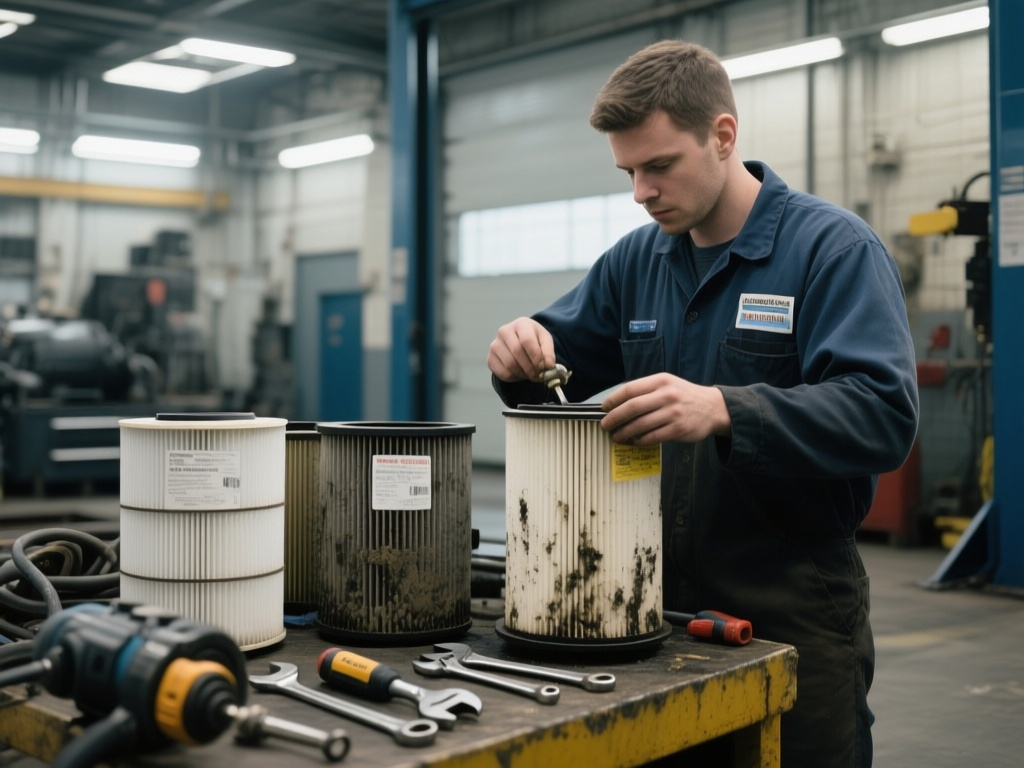
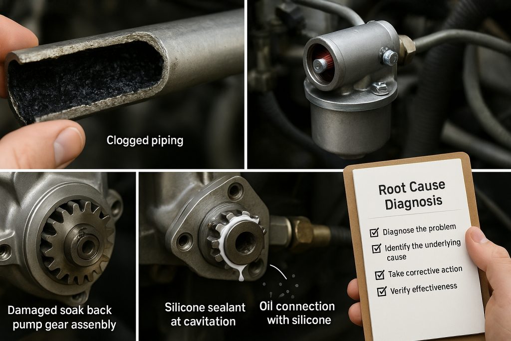
Governor tuning directly influences excitation response accuracy. A well-tuned governor stabilizes engine speed under load transients. You can then map excitation levels precisely to available torque. This coordination prevents engine lugging during high-demand scenarios. The system continuously balances current and voltage within thermal limits. Dynamic adjustment maintains best diesel-electric traction performance consistently. Procurement specialists should verify excitation controller calibration during component sourcing. Mikura International supplies alternator components meeting these critical control specifications.

Protection Against Overload

When the EMD 710 torque curve approaches its mechanical limits, onboard control systems activate protective measures automatically. You’ll find these safeguards prevent damage to both alternator and traction motors. The system continuously monitors electrical parameters against predefined thresholds.

Key protective actions include:

  1. Excitation reduction — Field current decreases to limit alternator output instantly.
  2. Current capping — Maximum traction motor protection engages to prevent winding damage.
  3. Thermal shutdown — Temperature sensors trigger load shedding before insulation degrades.
  4. Load regulator intervention — The system modulates engine demand to restore safe operating margins.

These protocols ensure you don’t exceed copper or thermal limits. They preserve component integrity during transient overload events. Your SD70’s reliability depends on these layered defenses operating without delay.

Implications for Rail Engineers and Procurement

emd 710 torque fuel efficiency

When you evaluate the EMD 710 torque curve, you must assess its direct impact on adhesion management and traction effort delivery. Your maintenance planning should account for alternator thermal limits and excitation system wear patterns. These factors collectively determine fuel efficiency and long-term operational costs across your SD70 fleet.

Adhesion and Traction Management

Because stable torque delivery directly governs wheel-rail interaction, adhesion management becomes a core powertrain function. The SD70’s flat EMD 710 torque curve minimizes erratic wheel slip behavior. You gain predictable traction effort across all operating notches. Traction control logic relies on this consistency for effective modulation.

Stable alternator output supports adhesion management through four mechanisms:

  1. Consistent current delivery prevents sudden torque spikes at traction motors.
  2. Rapid excitation adjustment reduces wheel slip response time markedly.
  3. Predictable power boundaries simplify traction control logic calibration.
  4. Thermal margin preservation sustains high tractive effort during prolonged demands.

This integration reduces wheel and rail wear measurably. You also achieve higher net hauling capacity per locomotive. Procurement decisions should prioritize components preserving this adhesion-optimized architecture.

Maintenance and Reliability Factors

Predictable torque loading directly extends component life across the SD70 powertrain. You’ll find that the EMD 710’s flat torque curve minimizes cyclic stress on alternator bearings and windings. This reduces lubrication wear on critical rotating assemblies markedly. Stable thermal profiles also prevent insulation degradation over extended service intervals.

When you maintain consistent operating conditions, filter maintenance becomes more predictable. Oil and air filtration schedules align with steady-state loading patterns. You won’t encounter the accelerated contamination rates that erratic power demands create.

For procurement specialists, this reliability translates into lower total cost of ownership. You’re sourcing components that operate within well-defined thermal and mechanical envelopes. Mikura International supplies EMD 710 engine parts engineered for these exact operating conditions. Rail engineers can specify replacements confidently using established performance data from SD70 fleet records.

Fuel Efficiency and Operational Costs

The EMD 710 torque curve’s flat plateau directly reduces specific fuel consumption across operating notches. You’ll find that stable mechanical input minimizes throttle hunting. The alternator converts energy with fewer transitional losses.

Key cost implications you should evaluate:

  1. Consistent torque delivery lowers fuel burn per gross ton-mile hauled.
  2. Reduced dynamic wheel slip events decrease rail and wheel wear costs.
  3. Optimized excitation control extends alternator insulation life, cutting overhaul intervals.
  4. Compatibility with regenerative braking systems recovers energy during grade descents.

These factors compound across fleet operations. Procurement specialists should model lifecycle costs against torque-alternator efficiency data. You’re not just buying components—you’re investing in sustained operational margins. Mikura International supplies EMD 710 engine parts engineered for these demanding efficiency standards.

Frequently Asked Questions

How Does the EMD 710 Torque Curve Affect Fuel Efficiency in SD70 Locomotives?

The EMD 710 torque curve improves your fuel efficiency by maintaining a flat torque plateau across operating notches. This allows precise fuel mapping that matches diesel injection to actual load demand. You’re avoiding over-fueling because the engine doesn’t chase erratic torque spentials. Your traction control system leverages this stability, reducing unnecessary throttle corrections. Consistent mechanical input means the alternator converts energy predictably, minimizing thermal losses and ensuring you extract maximum tractive effort per gallon consumed.

You’ll most commonly encounter brush wear on the exciter and main field circuits, requiring scheduled inspection intervals. Prolonged high-current operation accelerates insulation breakdown across stator windings, especially under heavy-haul thermal cycling. You should also monitor bearing degradation, rectifier diode failures, and excitation winding resistance drift. These issues compound when the load regulator operates near copper thermal limits. Mikura International supplies critical alternator components engineered for SD70 series reliability and extended service life.

Why Is Constant Horsepower Loading Important for Diesel-Electric Locomotive Performance?

Constant horsepower loading prevents up to 15% thermal efficiency loss across operating notches. When you maintain constant loading, your engine operates within its most effective torque-speed envelope consistently. This directly enhances traction stability by ensuring predictable current-voltage relationships at the alternator output. You’re balancing mechanical input against electrical demand seamlessly. Without it, your load regulator can’t map excitation accurately, risking engine lug or alternator overheating during heavy-haul freight operations.

How Do Ambient Temperature Variations Influence Alternator Thermal Limits During Heavy-Haul Operations?

Ambient temperature rises directly reduce your alternator’s heat dissipation capacity, triggering thermal derating of allowable current output. In heavy-haul operations, you’ll see excitation control systems reduce field current to protect copper and insulation limits. Your load management algorithms compensate by adjusting the torque-to-excitation mapping in real time. This prevents thermal runaway while maintaining stable traction effort. You must account for seasonal temperature extremes when specifying alternator cooling margins.

What Spare Parts Should Procurement Specialists Stock for SD70 Alternator Reliability?

You should stock a spare regulator assembly, alternator bearings, rectifier diodes, and excitation field components. These parts directly sustain SD70 main alternator reliability. Prioritize brush holders and insulation kits for thermal protection. Keep voltage regulator cards available for rapid field replacement. Mikura International supplies these critical components with proven compatibility. By maintaining this inventory, you’ll minimize unplanned downtime and preserve consistent diesel-electric traction performance across heavy-haul operations.

How does turbo soak back pump 40182032 impact locomotive fuel efficiency?

How does turbo soak back pump 40182032 impact locomotive fuel efficiency?

TL;DR

  • Critical Protection: The Turbo Soak Back Pump 40182032 provides essential auxiliary lubrication for EMD locomotive engines, circulating filtered oil for 30, 35 minutes after shutdown to prevent heat-induced damage.
  • Fuel Efficiency & Reliability: By preventing “oil coking” (the buildup of hard carbon deposits), the pump maintains peak turbocharger performance, which directly reduces fuel consumption and prevents costly unplanned downtime.
  • Component Longevity: The system ensures bearings are pre-lubricated before startup and cooled post-shutdown, effectively preventing shaft seizure, bearing degradation, and thermal breakdown of the oil.
  • Maintenance Best Practices: For optimal results, operators should follow strict installation procedures, monitor oil pressure regularly, and adhere to filter replacement schedules to protect the turbocharger’s rotating assembly.

Turbo Soak Back Pump 40182032 and Fuel Efficiency

Locomotive maintenance managers often face significant challenges. Premature turbocharger failure is a major concern. This leads to costly repairs and unexpected downtime. These issues severely impact operational efficiency and budget. Mikura International understands these pain points.

  • Implement a strict maintenance schedule.
  • Monitor turbocharger performance regularly.
  • Ensure proper lubrication systems are active.
  • Address any warning signs immediately.
  • Use high-quality replacement parts.
  • Train staff on best practices.

Function and Role of Turbo Soak Back Pump 40182032

The Turbo Soak Back Pump 40182032 is an auxiliary lubrication system. It is vital for locomotive maintenance. This pump circulates filtered oil post-engine shutdown. This process significantly reduces oil coking. Reduced coking directly impacts fuel efficiency. It maintains optimal turbocharger performance.

This critical component supports EMD locomotive engines. It ensures the turbine wheel and rotating assembly remain lubricated. The pump prevents thermal breakdown. It extends the life of bearing assemblies. This proactive measure is key for engine reliability.

Impact of Oil Coking on Locomotive Fuel Efficiency

Oil coking is a severe problem. It causes bearing degradation within the turbocharger. This degradation decreases turbocharger efficiency. Consequently, increased fuel consumption occurs. It also leads to unplanned downtime and costly repairs.

Preventing oil coking is crucial. The Turbo Soak Back Pump 40182032 achieves this. It improves engine reliability and operational efficiency. Mikura International provides solutions to combat coking. This ensures sustained fuel efficiency for diesel locomotives.

Installation and Inspection Procedures for the Soak Back Pump

Proper installation of the Turbo Soak Back Pump 40182032 is essential. Begin with a preliminary inspection. Check the Soak Back Filter and all piping. Verify electric motor functionality. Ensure correct mounting of the pump unit. Route oil lines properly.

Specific torque values are critical. Use recommended line diameters. These steps ensure optimal operation. Regular inspection of the check valve testing is also vital. This prevents future issues with bearing lubrication. Mikura International provides expert guidance.

Operational Control and Automatic System Integration

The Turbo Soak Back Pump 40182032 operates automatically. The locomotive control computer manages it. It activates during engine shutdown cycles. The pump runs for 30-35 minutes. This prevents thermal buildup in the turbocharger. Maintaining turbocharger efficiency is paramount.

This automated process protects the rotating assembly. It ensures proper bearing lubrication. The system integrates seamlessly with the main lubrication system. This prevents oil oxidation and hydrocarbon cracking. It is a smart solution for locomotive maintenance.

Pre-startup Lubrication and Post-shutdown Cooling Cycles

Activating the Turbo Soak Back Pump 40182032 before startup is beneficial. This ensures bearings are pre-lubricated. Pre-lubrication reduces wear significantly. Post-shutdown circulation is equally important. It prevents heat-induced oil cracking and coking.

This continuous oil circulation preserves component longevity. It protects the main oil gallery. The process ensures the bearing clearance remains optimal. It prevents shaft seizure. This extends turbocharger service intervals.

Effects of Oil Coking on Bearing and Turbocharger Life

Oil coking causes severe damage. It leads to carbon deposits on bearing assemblies. This results in scoring and potential shaft seizure. These issues drastically shorten turbocharger life. They increase unplanned downtime.

Maintaining continuous oil circulation minimizes these damages. The Turbo Soak Back Pump 40182032 achieves this. It reduces thermal and mechanical wear. This extends turbocharger service life. It keeps the rotating assembly in prime condition.

Benefits of Continuous Oil Circulation Post-Shutdown

Continuous oil circulation post-shutdown offers significant benefits. It reduces thermal stress on turbo bearings. This prevents carbon buildup. It sustains optimal fuel efficiency over time. Studies indicate improved engine reliability.

The Turbo Soak Back Pump 40182032 ensures this circulation. It keeps oil temperatures below the thermal stability threshold. This prevents oil coking. It protects vital bearing assemblies. Mikura International supports enhanced component longevity.

Related Innovation

Patent · Jan 7, 1986

Function and Role of Turbo Soak Back Pump 40182032

Function and Role of Turbo Soak Back Pump 40182032

The Turbo Soak Back Pump 40182032 is a vital component. It operates as an auxiliary lubrication system. This system functions after engine shutdown. It circulates filtered oil to the turbocharger bearings. This action significantly reduces oil coking. Oil coking is a primary cause of turbocharger degradation. Preventing coking maintains optimal turbocharger performance. This directly enhances EMD locomotive engines fuel efficiency. The pump ensures continuous lubrication during critical cooling phases. This extends the service life of the turbocharger. It also contributes to overall engine reliability in EMD locomotive engines.

Impact of Oil Coking on Locomotive Fuel Efficiency

Oil coking directly harms locomotive fuel efficiency. It causes deposits on bearing assemblies. These deposits lead to increased friction and wear. This degrades turbocharger efficiency over time. A less efficient turbocharger means the engine works harder. This results in higher fuel consumption. It also causes increased emissions. Oil coking shortens the lifespan of critical components. This necessitates more frequent maintenance. It also leads to expensive repairs and unplanned downtime. The Turbo Soak Back Pump 40182032 actively prevents this. It maintains cleaner bearings. This ensures the turbocharger operates at peak efficiency. This directly translates to improved fuel economy.

Installation and Inspection Procedures

Proper installation of the Turbo Soak Back Pump 40182032 is critical. It ensures long-term locomotive maintenance success. Before installation, perform preliminary inspections. Check the soak back filter and piping for damage. Verify the integrity of the oil gallery network. Ensure all connections are clean and secure. Mount the pump according to manufacturer specifications. Route oil lines carefully to avoid kinks. Use correct torque values for all fasteners. Recommended line diameters must be used. These steps ensure optimal operation. Mikura International provides detailed guides for installation. Always follow these procedures for best results. This prevents costly unplanned downtime.

Operational Control and Automatic System Integration

The Turbo Soak Back Pump 40182032 integrates seamlessly. It connects with the locomotive’s control system. This ensures robust Turbocharger management. It activates automatically during engine shutdown cycles. This activation lasts for approximately 30-35 minutes. This timing is critical for preventing thermal buildup. The auxiliary cooling system circulates oil. This process cools the hot turbocharger bearing assemblies. This prevents thermal breakdown of the oil. This automatic operation requires no manual intervention. It ensures consistent protection. The locomotive control computer manages this system. Proper integration is key to maintaining turbocharger efficiency and Engine reliability.

Automated Auxiliary Cooling System Operation

The Turbo Soak Back Pump 40182032 functions as a vital auxiliary lubrication system. It activates automatically. This occurs immediately after the Diesel Prime Mover shuts down. The system circulates pressurized oil. This oil flows through the turbine wheel and bearing assemblies. This continuous flow prevents oil coking. Oil coking forms damaging carbon deposits. These deposits occur when residual heat bakes stagnant oil. Preventing this coking is crucial. It directly impacts locomotive fuel efficiency. Maintaining clean bearing clearances is essential. This extends the service intervals for EMD locomotive engines.

Preventing Thermal Breakdown and Carbon Deposits

Engine shutdown cycles generate significant residual heat. This heat concentrates in the turbocharger. Without the Turbo Soak Back Pump 40182032, oil stagnates. It reaches its thermal stability threshold. This causes rapid oil oxidation and hydrocarbon cracking. The result is harmful carbon deposits and thermal breakdown. These deposits adhere to bearing surfaces. They lead to increased friction and wear. This compromises the rotating assembly. Mikura International emphasizes preventing these issues. Continuous oil circulation post-shutdown is vital. It maintains bearing lubrication and cools components. This significantly reduces unplanned downtime.

Role of the Locomotive Control Computer

The locomotive control computer is central. It manages the Turbo Soak Back Pump 40182032. This computer monitors engine parameters. It initiates the soak back cycle precisely. This ensures the 30-35 minute run time. This duration is engineered for optimal cooling. It prevents heat-induced oil cracking. The system also performs check valve testing. This ensures proper oil flow. Effective integration maintains the main lubrication system integrity. It extends component longevity. This smart control prevents shaft seizure. It protects the critical bearing assemblies.

Benefits of Continuous Oil Circulation Post-Shutdown

Maintaining oil flow after shutdown offers significant benefits. It reduces thermal stress on turbo bearings. This prevents carbon buildup. This sustains optimal locomotive fuel efficiency over time. Studies indicate this practice extends turbocharger service life. It minimizes damages from thermal and mechanical wear. The Turbo Soak Back Pump 40182032 ensures this circulation. It draws oil from the oil gallery network. It filters it through the Soak Back Filter. This delivers clean oil to the bearing assemblies. This pre-lubrication also aids startup. It reduces initial wear. This protects your investment in EMD locomotive engines.

Pre-startup Lubrication and Post-shutdown Cooling Cycles

The Turbo Soak Back Pump 40182032 performs two vital functions. It ensures engine reliability. This pump prevents unplanned downtime.

Before engine startup, the Turbo Soak Back Pump 40182032 provides critical pre-lubrication to the bearing assemblies. This reduces wear during initial engine rotation. It prepares the rotating assembly for operation. This action prolongs component longevity for the diesel prime mover.

Post-shutdown, the pump maintains essential oil circulation. This prevents heat-induced oil cracking. It stops oil coking. This continuous flow after shutdown minimizes thermal stress on the turbine wheel and bearing assemblies. It is a key aspect of Turbocharger Lubrication.

The auxiliary lubrication system ensures the main lubrication system remains primed. This prevents dry starts. It protects critical components. This dual action significantly extends the service intervals of EMD locomotive engines.

This process is crucial for preventing Carbon deposits. It maintains Bearing clearance. It ensures the thermal stability threshold of the oil is not breached. Mikura International emphasizes these benefits.

Studies indicate that continuous oil flow after shutdown significantly reduces thermal stress on turbo bearings. This prevents carbon buildup. It sustains optimal fuel efficiency over time. This extends the turbocharger’s service life.

Effects of Oil Coking on Bearing and Turbocharger Life

Oil coking severely impacts bearing and turbocharger life. It forms hard carbon deposits on bearing surfaces. These deposits cause scoring and increased friction. This can lead to premature wear. In severe cases, it causes shaft seizure. This necessitates costly turbocharger replacement. The Turbo Soak Back Pump 40182032 mitigates these risks. It ensures continuous oil circulation. This prevents carbon buildup. This action reduces thermal and mechanical wear. It extends the turbocharger’s service life significantly. This protects your investment and reduces maintenance costs.

Impact of Oil Coking on Locomotive Fuel Efficiency

Oil coking directly impacts locomotive fuel efficiency. Bearing degradation from coking decreases turbocharger efficiency. This leads to increased fuel consumption. It also causes costly unplanned downtime. Preventing oil coking with the Turbo Soak Back Pump 40182032 improves engine reliability. It sustains optimal operational efficiency. This pump reduces thermal stress on turbo bearings. It prevents carbon deposits. This helps maintain consistent fuel efficiency over time.

Benefits of Continuous Oil Circulation Post-Shutdown

Maintaining oil flow after engine shutdown is crucial. The Turbo Soak Back Pump 40182032 provides this continuous circulation. It reduces thermal stress on turbo bearings. This prevents carbon buildup. It also minimizes oil oxidation and hydrocarbon cracking. This action sustains optimal fuel efficiency. It extends the service intervals for EMD locomotive engines. This proactive measure prevents costly repairs. It ensures longer component longevity for the rotating assembly.

Understanding Thermal Breakdown and Carbon Deposits

Thermal breakdown of oil is a primary cause of carbon deposits. High temperatures in the turbine wheel area lead to oil coking. When the main lubrication system shuts down, residual heat remains. This heat exceeds the oil’s thermal stability threshold. The Turbo Soak Back Pump 40182032 circulates cooler oil. This prevents localized overheating. It flushes away potential carbon-forming particles. This protects the bearing assemblies from damage. Mikura International emphasizes preventing thermal breakdown for optimal performance.

Benefits of Continuous Oil Circulation Post-Shutdown

Continuous oil circulation after engine shutdown offers critical advantages. It significantly reduces thermal stress on turbo bearings. This action prevents the formation of harmful carbon deposits. These deposits are a primary cause of premature wear. The Turbo Soak Back Pump 40182032 is essential here. It ensures critical bearing lubrication.

Preventing Thermal Breakdown and Carbon Deposits

Continuous circulation helps dissipate residual heat from the turbine wheel. This protects the oil from thermal breakdown. It maintains oil quality within the main lubrication system. This sustained protection helps the turbocharger perform optimally. This directly contributes to consistent fuel efficiency. Mikura International emphasizes this critical advantage.

Studies show this practice extends turbocharger life. It minimizes the need for unscheduled maintenance. This reduces unplanned downtime for diesel locomotive engines. The auxiliary lubrication system prevents hydrocarbon cracking. This protects the rotating assembly.

Impact of Oil Coking on Locomotive Fuel Efficiency

Oil coking severely impacts locomotive fuel efficiency. It leads to bearing degradation within the turbocharger. This decreases overall turbocharger efficiency. In turn, this causes increased fuel consumption. Preventing coking with the Turbo Soak Back Pump 40182032 improves reliability. It enhances operational efficiency. The pump maintains the thermal stability threshold of the oil. This prevents carbon deposits from forming. These deposits restrict oil flow within the oil gallery network.

Effects of Oil Coking on Bearing and Turbocharger Life

Oil coking causes hard carbon deposits on bearing surfaces. These deposits lead to scoring and increased friction. This accelerates premature wear of bearing assemblies. In severe cases, it can cause shaft seizure. This necessitates costly turbocharger replacement. The Turbo Soak Back Pump 40182032 mitigates these risks. It ensures continuous oil circulation. This prevents carbon buildup. This action reduces thermal and mechanical wear. It extends the service intervals for EMD locomotive engines.

Expert Insight

“Turbo soak-back pumps are essential for maintaining the thermal stability threshold of the oil immediately upon engine shutdown; by ensuring continuous circulation, they prevent oil from being burnt and baked to the shaft, effectively avoiding the hard carbon deposits and coking that lead to expensive bearing degradation and turbocharger failure.” , Heavy-Duty Equipment Engineering Specialist

Understanding Turbocharger Lubrication

Turbochargers operate at extreme temperatures. Their bearings require constant, clean oil. The main lubrication system provides pressurized oil. This occurs during engine operation. Oil flows through an intricate oil gallery network. After engine shutdown, the main lube pump stops. Residual heat can then cause oil to bake onto hot surfaces. This leads to oil coking. This is where the Turbo Soak Back Pump 40182032 becomes indispensable. It ensures vital lubrication continues. This protects against thermal breakdown. It safeguards the entire rotating assembly. Proper bearing lubrication is key to engine reliability.

Function and Role of Turbo Soak Back Pump 40182032

The Turbo Soak Back Pump 40182032 functions as an auxiliary lubrication system. It circulates filtered oil post-shutdown. This significantly reduces oil coking. It maintains peak turbocharger performance. This directly impacts locomotive fuel efficiency. The pump ensures continuous flow. This prevents heat-induced damage to critical bearing assemblies. Mikura International provides reliable components for this system.

Impact of Oil Coking on Locomotive Fuel Efficiency

Oil coking causes rapid bearing degradation. This decreases turbocharger efficiency. It leads to increased fuel consumption. It also results in costly unplanned downtime. Preventing coking with the Turbo Soak Back Pump 40182032 improves reliability. It enhances operational efficiency. This protects your investment in diesel locomotive engines. It extends component longevity for critical parts like the turbine wheel.

Preventing Thermal Breakdown and Carbon Deposits

Continuous oil circulation after engine shutdown offers critical advantages. It significantly reduces thermal stress on turbo bearings. This action prevents the formation of harmful carbon deposits. These deposits are a primary cause of premature wear. The Turbo Soak Back Pump 40182032 is essential here. It ensures critical bearing lubrication. This safeguards the entire rotating assembly. It maintains the thermal stability threshold of the oil. This prevents hydrocarbon cracking and oil oxidation.

Common Pain Points and Solutions

Spare parts sourcing managers face significant challenges. Finding reliable components is often difficult. Ensuring timely delivery presents another hurdle. Dealing with unexpected component failures is a common pain point. The Turbo Soak Back Pump 40182032 directly addresses these issues. It significantly reduces turbocharger failures. This lowers costly unplanned downtime. Mikura International guarantees on-time delivery of quality parts. Our focus is on solving your operational problems. We provide solutions that enhance engine reliability. This helps manage service intervals effectively. We ensure your EMD locomotive engines run efficiently.

FeatureWithout Soak Back PumpWith Turbo Soak Back Pump 40182032
Oil Coking RiskHighLow
Turbocharger LifespanReducedExtended
Fuel EfficiencyCompromisedMaintained / Improved
Bearing WearSignificantMinimal
Unplanned DowntimeFrequentReduced
Maintenance CostsHigherLower
Engine ReliabilityLowerHigher

Function and Role of Turbo Soak Back Pump 40182032

The Turbo Soak Back Pump 40182032 is an auxiliary lubrication system. It operates after engine shutdown. This pump circulates filtered oil. Its primary role is to reduce oil coking. This directly impacts locomotive fuel efficiency. Maintaining turbocharger performance is key. The pump prevents residual heat from damaging bearing assemblies.

Impact of Oil Coking on Locomotive Fuel Efficiency

Oil coking leads to severe bearing degradation. This decreases turbocharger efficiency. Degraded turbochargers cause increased fuel consumption. This results in costly unplanned downtime. Preventing coking with the soak back pump improves reliability. It enhances overall operational efficiency. This protects your diesel locomotive investment.

Installation and Inspection Procedures

Proper installation procedures are critical. Begin with a preliminary inspection. Check filters, piping, and the electric motor functionality. Ensure correct mounting of the Turbo Soak Back Pump 40182032. Route oil lines precisely. Adhere to specific torque values. Use recommended line diameters. This ensures optimal operation and component longevity.

Operational Control and Automatic System Integration

The Turbo Soak Back Pump 40182032 integrates automatically. The locomotive control computer manages its activation. It engages during engine shutdown cycles. The pump typically runs for 30-35 minutes. This prevents thermal buildup. This is essential for maintaining turbocharger efficiency. It safeguards the rotating assembly.

Pre-startup Lubrication and Post-shutdown Cooling Cycles

Activating the Turbo Soak Back Pump 40182032 before startup is beneficial. It ensures bearing lubrication is established. This reduces initial wear on bearing assemblies. Post-shutdown circulation is equally vital. It prevents heat-induced oil oxidation. This stops hydrocarbon cracking and carbon deposits. This maintains the thermal stability threshold.

Effects of Oil Coking on Bearing and Turbocharger Life

Oil coking causes damaging deposits. It leads to scoring and potential shaft seizure. Maintaining continuous oil circulation minimizes these damages. This is achieved by the Turbo Soak Back Pump 40182032. It extends turbocharger service life. It reduces thermal and mechanical wear. This preserves bearing clearance.

Benefits of Continuous Oil Circulation Post-Shutdown

Maintaining oil flow after shutdown reduces thermal stress. This protects turbo bearings. It prevents carbon buildup. Studies show this sustains optimal fuel efficiency over time. The auxiliary cooling system supports this. This ensures the main lubrication system remains effective. The pump draws from the main oil gallery.

Maintaining Optimal Thermal Stability Threshold

Maintaining Optimal Thermal Stability Threshold

The thermal stability threshold of lubricating oil is crucial. High temperatures after engine shutdown can exceed this threshold. This causes oil to degrade. It forms carbon deposits. These deposits lead to hydrocarbon cracking. The Turbo Soak Back Pump 40182032 prevents this. It circulates cooler oil. This keeps bearing assemblies temperatures below critical levels. It protects the oil’s integrity. It ensures effective lubrication. Maintaining this threshold is vital. It preserves component longevity. It sustains peak turbocharger management. This supports locomotive fuel efficiency.

Function and Role of Turbo Soak Back Pump 40182032

The Turbo Soak Back Pump 40182032 acts as an auxiliary lubrication system. It significantly reduces oil coking. It circulates filtered oil post-shutdown. This maintains turbocharger performance. Ultimately, this directly impacts locomotive fuel efficiency. Mikura International supplies these vital pumps. They enhance the reliability of your diesel locomotive.

Impact of Oil Coking on Locomotive Fuel Efficiency

Oil coking severely impacts locomotive fuel efficiency. It causes bearing degradation. This decreases turbocharger efficiency. Increased fuel consumption results. It leads to costly unplanned downtime. Preventing coking with the Turbo Soak Back Pump 40182032 is key. It improves engine reliability and operational efficiency. This protects your EMD locomotive engines.

Installation and Inspection Procedures

Proper installation procedures are critical. First, inspect filters and piping. Check electric motor functionality. Ensure correct mounting. Route lines precisely. Mikura International provides detailed guidelines. Recommended specific torque values exist. Use correct line diameters. This ensures optimal operation of the cooling system.

Operational Control and Automatic System Integration

The Turbo Soak Back Pump 40182032 operates automatically. The locomotive control computer controls it. It activates during engine shutdown cycles. It runs for 30-35 minutes. This prevents thermal buildup. This is essential for maintaining turbocharger lubrication. It ensures sustained engine reliability.

Pre-startup Lubrication and Post-shutdown Cooling Cycles

Activating the Turbo Soak Back Pump 40182032 before startup ensures pre-lubrication. This reduces wear on bearing assemblies. Post-shutdown circulation prevents heat-induced oil cracking. It stops carbon deposits formation. This extends the life of the turbine wheel and rotating assembly.

Effects of Oil Coking on Bearing and Turbocharger Life

Oil coking causes deposits and scoring. It can lead to shaft seizure. Maintaining continuous oil circulation minimizes these damages. This extends turbocharger service life. It reduces thermal and mechanical wear. This protects your investment in locomotive maintenance.

Benefits of Continuous Oil Circulation Post-Shutdown

Maintaining oil flow after shutdown reduces thermal stress. This protects turbo bearings. It prevents carbon buildup. This sustains optimal locomotive fuel efficiency over time. The Turbo Soak Back Pump 40182032 ensures these benefits. It uses the main lubrication system effectively. It provides pressurized oil through the oil gallery network.

Expert Insight

“The Turbo Lube Oil Soak Back Pump (40182032) is critical for locomotive longevity; by ensuring pre-lubrication and post-shutdown circulation, it prevents heat-induced oil cracking and carbon deposits that otherwise lead to shaft seizure and premature turbocharger failure.” , Locomotive Engineering Specialist

Monitoring and Pressure Testing the Soak Back System

Monitoring and Pressure Testing the Soak Back System

Regular monitoring of the Turbo Soak Back Pump 40182032 system is essential. Check oil pressure and flow rates. Ensure the pump activates correctly after engine shutdown cycles. Perform pressure testing periodically. This verifies system integrity. It identifies potential leaks or blockages. Inspect the check valve testing. This ensures proper oil flow direction. Regular checks prevent system malfunctions. They guarantee continuous protection for the turbocharger. Mikura International recommends a strict monitoring schedule. This proactive approach prevents costly failures. It supports overall locomotive maintenance efforts.

Operational Control and Automatic System Integration

The Turbo Soak Back Pump 40182032 is controlled automatically. The locomotive control computer manages its activation. It engages during engine shutdown cycles. The pump operates for 30-35 minutes. This prevents thermal buildup. This action maintains turbocharger efficiency. Automated operation ensures consistent performance. It reduces manual intervention needs. This system integration is vital for engine reliability. It prevents issues like oil coking.

Pre-startup Lubrication and Post-shutdown Cooling Cycles

Activating the Turbo Soak Back Pump 40182032 before startup is critical. It ensures bearing assemblies are pre-lubricated. This significantly reduces initial wear. Post-shutdown circulation prevents heat-induced oil cracking. It stops carbon deposits from forming. This dual-phase operation extends component longevity. It protects the rotating assembly. This system prevents thermal breakdown. It is an essential part of effective turbocharger management.

Benefits of Continuous Oil Circulation Post-Shutdown

Maintaining oil flow after shutdown is crucial. Studies show it reduces thermal stress on turbocharger bearings. This prevents carbon buildup. It sustains optimal fuel efficiency over time. Continuous circulation also minimizes oil oxidation. It maintains the thermal stability threshold. This process protects the turbine wheel. It ensures the diesel prime mover operates efficiently. This proactive cooling is a cornerstone of locomotive maintenance.

System Maintenance: Filter Replacement and Cleaning

Effective system maintenance includes regular filter replacement. The soak back filter traps contaminants. A clogged filter reduces oil flow. This compromises lubrication. Replace filters according to service intervals. Clean the system piping as needed. Inspect for any debris or sludge buildup. Proper cleaning ensures optimal oil quality. This prevents abrasive wear on bearing assemblies. This routine maintenance is vital. It supports the component longevity of the Turbo Soak Back Pump 40182032. It also protects the turbocharger’s rotating assembly.

Impact of Oil Coking on Locomotive Fuel Efficiency

Oil coking significantly impacts locomotive fuel efficiency. It leads to bearing degradation within the turbocharger. This decreases overall turbocharger efficiency. Increased fuel consumption is a direct result. Costly unplanned downtime also occurs. Preventing oil coking with the Turbo Soak Back Pump 40182032 improves engine reliability. It also enhances operational efficiency for diesel locomotive engines. Mikura International emphasizes preventative measures.

Effects of Oil Coking on Bearing and Turbocharger Life

Oil coking causes detrimental deposits. It leads to scoring and potential shaft seizure. Maintaining continuous oil circulation minimizes these damages. This extends turbocharger service life. It reduces thermal and mechanical wear. The Turbo Soak Back Pump 40182032 is crucial here. It prevents thermal breakdown and carbon deposits. This protects the turbine wheel and its bearings. Mikura International parts ensure robust performance.

Benefits of Continuous Oil Circulation Post-Shutdown

Continuous oil flow after engine shutdown is vital. It reduces thermal stress on turbo bearings. This prevents carbon buildup. Optimal fuel efficiency is sustained over time. The Turbo Soak Back Pump 40182032 facilitates this. It provides auxiliary lubrication during engine shutdown cycles. This process maintains the thermal stability threshold of the oil. It prevents oil oxidation and hydrocarbon cracking. This ensures cleaner bearing lubrication.

Materials and Design Features of Pump and Piping

The Turbo Soak Back Pump 40182032 is built for durability. It uses robust materials. These materials withstand harsh locomotive environments. The piping system is designed for high-pressure oil flow. It resists corrosion and vibration. The pump motor is engineered for continuous operation. These design features ensure reliable performance. They contribute to the component’s extended lifespan. Mikura International supplies parts meeting these high standards. Quality materials prevent premature failure. They ensure consistent auxiliary lubrication.

Control System Logic and Timing of Pump Activation

The locomotive control computer governs pump activation. Its logic dictates precise timing. The Turbo Soak Back Pump 40182032 engages immediately after engine shutdown. This is part of the auxiliary cooling system. It runs for a programmed duration. This duration is typically 30-35 minutes. This ensures adequate cooling. It prevents oil coking. The control system monitors engine parameters. It ensures the pump operates only when needed. This intelligent control maximizes efficiency. It minimizes energy consumption. Proper calibration of this logic is crucial. It ensures optimal protection for the turbocharger. This system is vital for Locomotive Maintenance.

Operational Control and Automatic System Integration

The Turbo Soak Back Pump 40182032 is controlled automatically. The locomotive’s computer manages this. It activates during engine shutdown cycles. This prevents thermal buildup. This is essential for maintaining turbocharger efficiency. The pump circulates oil for 30-35 minutes. This post-shutdown cooling prevents oil oxidation. It stops hydrocarbon cracking. This protects the turbine wheel and rotating assembly. It ensures component longevity. Mikura International emphasizes this critical integration.

Pre-startup Lubrication and Post-shutdown Cooling Cycles

Activating the Turbo Soak Back Pump 40182032 before startup is key. It ensures bearing assemblies are pre-lubricated. This reduces wear significantly. Similarly, post-shutdown circulation is vital. It prevents heat-induced oil cracking and oil coking. This continuous oil circulation protects the main lubrication system. It safeguards the oil gallery network. This dual-cycle approach extends turbocharger service intervals. It enhances engine reliability for Diesel Prime Mover applications.

Preventing Shaft Seizure and Extending Component Longevity

Shaft seizure is a catastrophic turbocharger failure. It often results from severe oil coking. Lack of lubrication during engine shutdown cycles is a key factor. The Turbo Soak Back Pump 40182032 directly prevents this. It maintains a continuous supply of oil. This keeps the turbine wheel shaft and bearing assemblies lubricated. This action dramatically extends component longevity. It reduces the risk of expensive repairs. It ensures the rotating assembly spins freely. This contributes to overall engine reliability. Mikura International provides solutions for lasting performance.

Effects of Oil Coking on Bearing and Turbocharger Life

Oil coking causes significant damage. It leads to carbon deposits on critical surfaces. This includes bearing assemblies and the turbine wheel shaft. These deposits cause scoring and increased friction. This accelerates wear and reduces bearing lubrication effectiveness. Ultimately, coking can lead to complete shaft seizure. Maintaining continuous oil circulation minimizes these damages. It extends turbocharger management service life. This reduces thermal and mechanical wear. This is vital for diesel locomotive performance.

Benefits of Continuous Oil Circulation Post-Shutdown

Studies show maintaining oil flow after shutdown is crucial. The auxiliary lubrication provided by the Turbo Soak Back Pump 40182032 reduces thermal stress. This protects turbocharger lubrication bearings. It prevents carbon deposits from forming. This sustains optimal locomotive fuel efficiency over time. The pump circulates pressurized oil through the oil gallery network. This prevents thermal breakdown. It stops oil oxidation and hydrocarbon cracking. This ensures the oil’s thermal stability threshold is not exceeded.

Function and Role of Turbo Soak Back Pump 40182032

The Turbo Soak Back Pump 40182032 operates as an auxiliary lubrication system. It activates post-shutdown. This circulates filtered oil through the turbocharger lubrication system. This action directly reduces oil coking. By maintaining bearing lubrication, it sustains turbocharger management performance. This positively impacts locomotive fuel efficiency. It is a critical component for diesel prime mover longevity. Mikura International supplies these vital parts for EMD locomotive engines.

Pre-startup Lubrication and Post-shutdown Cooling Cycles

Activating the soak back pump before startup ensures bearing assemblies are pre-lubricated. This significantly reduces wear during initial engine operation. Similarly, post-shutdown circulation prevents heat-induced oil cracking and oil coking. This comprehensive approach maximizes component longevity. It minimizes unplanned downtime. This two-phase lubrication strategy is key to robust locomotive maintenance. It ensures optimal turbocharger management.

Ensuring Proper Bearing Clearance and Oil Oxidation Control

Maintaining correct bearing clearance is vital. Oil coking reduces this clearance. This increases friction and wear. The Turbo Soak Back Pump 40182032 prevents deposit formation. This preserves proper clearance. It also helps control oil oxidation. High temperatures accelerate oxidation. Oxidized oil forms sludge and varnish. The auxiliary cooling system reduces oil temperatures. This slows oxidation rates. This maintains oil quality. It ensures effective bearing lubrication. This dual benefit protects critical turbocharger components.

Impact of Oil Coking on Locomotive Fuel Efficiency

Oil coking severely impacts locomotive fuel efficiency. It degrades bearing assemblies. This decreases turbocharger efficiency. Increased fuel consumption results. Costly unplanned downtime also occurs. Preventing coking with the Turbo Soak Back Pump 40182032 improves reliability. It maintains optimal operational efficiency. Mikura International provides solutions for this.

Benefits of Continuous Oil Circulation Post-Shutdown

Continuous oil circulation post-shutdown is crucial. It reduces thermal stress on turbo bearings. This prevents carbon deposits. It sustains optimal fuel efficiency over time. The Turbo Soak Back Pump 40182032 ensures this circulation. This extends the life of the rotating assembly. It minimizes the risk of shaft seizure.

Effects of Oil Coking on Bearing and Turbocharger Life

Oil coking causes significant damage. It leads to deposits and scoring. Potential shaft seizure is a risk. The Turbo Soak Back Pump 40182032 minimizes these damages. It maintains continuous oil circulation. This extends turbocharger service life. It reduces thermal and mechanical wear. This protects the turbine wheel.

Pre-startup Lubrication and Post-shutdown Cooling Cycles

Pre-startup lubrication is essential. Activating the Turbo Soak Back Pump 40182032 ensures this. Bearings are pre-lubricated. This reduces wear significantly. Post-shutdown circulation prevents heat-induced oil cracking. It stops coking. This maintains the thermal stability threshold of the oil. It supports overall engine reliability.

Frequently Asked Questions

What is the primary function of the Turbo Soak Back Pump 40182032?

The Turbo Soak Back Pump 40182032 delivers auxiliary lubrication. It supplies oil to turbocharger bearings after engine shutdown. This prevents oil coking and thermal breakdown.

How does oil coking affect locomotive fuel efficiency?

Oil coking degrades turbocharger bearing assemblies. This reduces efficiency of the rotating assembly. The diesel prime mover must work harder. This increases fuel consumption and lowers engine reliability. Preventing coking enhances fuel efficiency.

For how long does the Turbo Soak Back Pump 40182032 typically operate after engine shutdown?

It operates for about 30-35 minutes after engine shutdown. This critical cycle ensures proper cooling system function. It also maintains bearing lubrication, preventing carbon deposits.

Why is pre-lubrication important for a turbocharger?

Pre-lubrication ensures bearings are oiled before engine startup. This reduces wear during initial rotation. It protects the turbine wheel and rotating assembly. This extends component longevity and minimizes unplanned downtime.

What are the critical components of the auxiliary lubrication system?

The system includes the Turbo Soak Back Pump 40182032 itself. It also uses a soak back filter and specific piping. A check valve testing ensures proper oil flow. These components prevent shaft seizure and maintain bearing clearance.

How does the Turbo Soak Back Pump 40182032 prevent thermal breakdown?

It circulates oil after the main lubrication system stops. This removes residual heat from the turbocharger. This keeps oil below its thermal stability threshold. It prevents hydrocarbon cracking and carbon deposits.

Where can I source reliable Turbo Soak Back Pump 40182032 parts?

Mikura International is a certified global supplier. We offer reliable, cost-effective replacement components. This includes the Turbo Soak Back Pump 40182032. We ensure quality for EMD locomotive engines.

References

What Are Common Failure Symptoms of Locomotive Turbo Soak Back Pump 40182032?

What Are Common Failure Symptoms of Locomotive Turbo Soak Back Pump 40182032?

If your locomotive turbo soak back pump 40182032 is starting to fail, the most frustrating issue is usually what happens right after shutdown or during the next startup: the turbo does not receive proper post-shutdown oil circulation, heat remains trapped in the turbocharger, and crews or maintenance teams begin seeing rising wear, delayed spool-up, abnormal turbo noise, and inconsistent lubrication-related alarms.

In locomotive service, catching these symptoms early is critical because a weak soak back pump can quickly turn a manageable maintenance issue into expensive turbocharger damage and unwanted locomotive downtime.

  • Slower-than-normal turbocharger spool-up after restart
  • Extended turbo lag under locomotive load
  • Reduced or irregular oil circulation during post-shutdown cooling
  • Whining, grinding, or sputtering noise from the soak back pump
  • Low oil pressure below expected range during pump operation
  • Erratic pressure fluctuation instead of steady flow
  • Zero or unusually low current draw at the pump leads
  • Intermittent pump operation after locomotive shutdown
  • Signs of overheating or oil coking around the turbocharger
  • Increased risk of premature turbo bearing wear
SymptomWhat It Usually MeansImmediate Locomotive Maintenance Action
Slow turbo spool-upInadequate oil flow or weak pump performanceInspect pump output and oil line restriction
Pump whining or grindingInternal wear, cavitation, or bearing damageRemove and inspect pump condition
Low pressure readingFailing pump, leakage, or blocked suctionCheck pressure, fittings, and oil supply path
Erratic pressure spikesElectrical instability or internal pump faultTest voltage supply and pump response
Zero current drawOpen circuit, failed motor, or disconnected leadInspect wiring, fuse, relay, and terminals
Intermittent post-shutdown operationFaulty control signal or failing motorVerify control logic and shutdown-cycle activation
Excess turbo heat soakInsufficient post-shutdown lubrication/coolingInspect soak back system before next locomotive run

When your locomotive turbo soak back pump 40182032 starts failing, common symptoms include degraded turbocharger spool-up, extended turbo lag, and inconsistent oil flow during post-shutdown cycles.

The pump may also produce high-pitched whining, grinding, or sputtering sounds, all of which can indicate internal wear or oil delivery problems within the locomotive’s turbo support system.

A failing pump often shows up in pressure behavior as well.

Pressure readings may drop below 10 PSI or fluctuate erratically above 35 PSI, pointing to unstable pump performance, blockage, leakage, or internal component damage.

From the electrical side, maintenance personnel may observe zero or reduced current draw at the pump leads, which usually suggests wiring faults, motor failure, poor connections, or a defective control circuit.

Each of these symptoms is an important warning sign in locomotive turbocharger protection and post-shutdown lubrication management.

Identifying the symptom early and linking it to the correct root cause can help prevent accelerated turbo wear, avoid unscheduled locomotive downtime, and reduce the risk of a much more costly turbocharger replacement.

Key Takeaways

  • Post-shutdown oil pressure drops below 10 PSI on the gauge, indicating pump failure, blocked lines, or relief valve faults.
  • Frothy, air-filled oil at the outlet confirms cavitation, collapsing the oil film and starving turbocharger bearings.
  • Zero current draw at pump leads signals open DC supply wiring or blown fuses in the 40–90 VDC circuit.
  • Intermittent or absent pre-lube flow at the turbo inlet indicates a failing pump or compromised suction line integrity.
  • Rising high-pitched whine or grinding during soak cycles points to bearing fatigue, rotor imbalance, or internal mechanical wear.

What the Locomotive Turbo Soak Back Pump 40182032 Actually Does

turbocharger oil circulation protection

The turbo soak back pump 40182032 is an electric auxiliary pump that keeps engine oil circulating through the turbocharger bearing cavity after shutdown and before startup—two critical windows when the main lube pump isn’t running.

After shutdown, residual heat migrates from the turbine into the bearing housing, a phenomenon called heat soakback. Without active oil flow, that heat cooks residual oil into carbonaceous deposits that degrade bearing surfaces. The pump runs for roughly 30–35 minutes post-shutdown, continuously removing that heat and preventing coke formation.

Before startup, the pump handles turbo prelubrication by circulating filtered oil through the bearings for several minutes before fuel injection begins. It keeps running until main lube pressure reaches approximately 20 PSI, at which point a pressure-operated check valve blocks soak-back flow and the main system takes over. Oil supply pressure during pump operation stays within a nominal 10–35 PSI range.

The First Signs Your 40182032 Is Starting to Fail

When your 40182032 begins to fail, you’ll likely notice reduced turbocharger spool-up first—the turbo takes longer to reach operating speed because oil pressure delivered during pre-lube or post-shutdown cycles is insufficient to maintain proper bearing lubrication. You may also hear unusual whining or grinding noises from the pump assembly, signaling early bearing wear or rotor imbalance that will worsen without intervention. Fluctuating boost pressure follows as a direct consequence, since inconsistent lubrication degrades turbo bearing integrity and disrupts the stable rotor speeds needed to maintain steady airflow to the engine.

Reduced Turbo Spool-Up

Sluggish turbocharger response during acceleration is often the earliest indicator that your 40182032 soak back pump is beginning to fail. When the pump isn’t pre-lubricating bearings before fuel injection, you’ll notice pronounced turbo lag and compromised spool dynamics during initial RPM rise. Monitor your compressor bearing oil pressure closely—readings below 10 PSI during pre-lube cycles signal inadequate pump flow before the pressure stabilizes within the expected 10–35 PSI range. You should also track whether the pump energizes during its required 30–35 minute post-shutdown sequence. Skipped or intermittent cycles directly degrade subsequent spool-up performance. Listen for cavitation or unusual humming during pump operation, as these sounds indicate restricted suction or a failing drive mechanism that’ll worsen spool dynamics over time.

Unusual Whining Noises

Beyond sluggish spool-up, your 40182032 will often announce deeper mechanical trouble through sound before any pressure gauge confirms a problem. A rising high-pitched whine during shutdown or pre-lube cycles typically signals bearing fatigue or rotor imbalance developing inside the pump. If that whine intensifies proportionally with pump voltage, suspect motor winding degradation or voltage harmonics driving higher current draw toward the 12 A peak threshold.

A sudden shift from a soft whirr to harsh metallic noise within the 30–35 minute post-shutdown soak cycle frequently precedes total oil flow loss, often caused by suction-line cavitation. When the whining stops upon de-energizing the pump but returns immediately on restart, you’re likely dealing with an electrical fault in the motor or inverter drive rather than a transient oil condition.

Fluctuating Boost Pressure

Watch for these warning indicators:

  • Post-shutdown oil pressure dropping below 10 PSI on your 0–100 PSI gauge during the soak cycle
  • Erratic spikes above 35 PSI suggesting relief valve malfunction or internal blockage
  • Inconsistent pre-lube flow at the turbo inlet after pump energization
  • Air entrainment or foaming visible in the filter housing during operation
  • Repeated manual restarts required to re-prime the soak-back system

Each symptom compounds the next—address them before bearing failure forces a full turbocharger replacement.

What Strange Pump Noises Are Really Telling You

Strange noises from your soak back pump 40182032 often carry specific diagnostic information you shouldn’t ignore. A grinding or rumbling during the 30–35 minute post-shutdown run points directly to bearing wear or rotor rubbing—don’t let it continue operating under those conditions. Intermittent clicking on start or stop suggests failing motor brushes or a deteriorating AC motor rotor; check continuity and winding resistance immediately.

High-pitched whining that shifts with voltage typically signals cavitation from air ingestion caused by a restricted suction line. Verify your inlet tubing measures at least 5/8″ and remains fully unobstructed to sustain the required 10–35 PSI output. A sputtering sound during priming confirms air in the line—disconnect the outlet at the turbo filter head and run the pump until you see continuous oil flow.

A loud hum approaching the 12 A maximum at 74 VDC means shut it down and inspect the motor and bypass valves immediately.

Wiring and Sensor Failures That Kill the 40182032 Pump

electrical and sensor failures

Once you’ve ruled out mechanical noise sources in the 40182032, shift your attention to the electrical and sensor circuits that control it—because a perfectly functional pump motor still won’t run if its supply wiring, control signals, or feedback sensors are compromised.

Start sensor diagnostics and control wiring inspections by targeting these five critical failure points:

  • Zero current draw at pump leads — open DC supply wiring or blown fuses in the 40–90 VDC circuit
  • Voltage drop under load — corroded grounds or chafed harnesses causing the pump to stall despite nominal battery voltage
  • Abnormal winding resistance — failed motor windings reading open or shorted against factory specs
  • No automatic activation — burned relay contacts or faulty computer enable signals blocking post-shutdown sequencing
  • Forced inhibit faults — bad pressure/flow sensors or stuck check valves feeding false fault data to control logic

Measure methodically. Each failure point narrows your diagnosis.

Oil Starvation and Flow Problems in a Failing 40182032

Behind every 40182032 failure mode you’ve diagnosed so far—noise, wiring faults, sensor errors—oil starvation is the consequence that destroys turbocharger bearings if you don’t catch it fast.

When the pump’s running but compressor bearing oil passage pressure reads below 10 PSI, you’ve got either pump failure or inlet blockage restricting flow before it reaches critical lubrication points. Disconnect the outlet and watch for continuous, steady oil flow during priming—slow or intermittent delivery signals air cavitation from a restricted suction line or a leaking inlet fitting drawing air instead of oil.

Frothy, air-filled oil at the outlet confirms cavitation is collapsing your oil film across turbo bearings. Check the suction line for kinks, collapsed sections, or loose pickup connections immediately. Internal pump wear also drops outlet pressure below the 10–35 PSI operating threshold, so always verify pressure with a gauge before condemning external plumbing alone.

What 40182032 Pump Failure Does to Your Turbocharger After Shutdown

turbocharger heat soak coking

When the 40182032 fails and post-shutdown circulation stops, your turbocharger enters a heat-soak condition it can’t recover from on its own. Turbine temperatures near 1,000°F remain trapped in the bearing cavity while oil flow stops completely, triggering turbo bearing-coking that hardens residual lubricant into tar-like deposits.

Every failed cooldown cycle compounds the damage:

  • Coked oil clogs passages, starving bearings of the film thickness they need to survive
  • Blocked relief valves accelerate pressure loss during the next start cycle
  • Start-up wear intensifies as dry bearings absorb full rotor load at 100,000+ RPM
  • Shaft surfaces develop bluish-yellow heat tinting, signaling irreversible metallurgical damage
  • Scored bearing surfaces appear within hundreds of operating hours instead of full service intervals

You’re not just shortening turbo life — you’re forcing premature replacement or major overhaul on a timeline the manufacturer never intended.

How to Confirm the 40182032 Pump Is the Root Cause

Confirming the 40182032 as the root cause requires isolating it systematically before condemning the turbocharger or surrounding components. Start with electrical isolation: clamp a meter around the pump leads and verify it draws up to 12 A at 74 VDC during post-shutdown cycles. No current or markedly reduced draw points directly to motor failure or an open circuit.

Next, perform flow visualization by disconnecting the outlet at the turbocharger filter head with fuel disabled. Continuous, bubble-free oil flow confirms suction integrity; intermittent flow or air entrainment signals pump or suction-line leakage. Follow that with a pressure test—install a 0–100 PSI gauge at the compressor bearing oil passage and confirm 10–35 PSI while the pump runs engine-off. Pressures outside that range indicate pump or relief valve faults. Finally, bypass the filter and compare flow; restored output confirms a blockage rather than pump failure.

Replace or Repair Your Soak Back Pump 40182032?

diagnostics determine repair vs replacement

Once you’ve isolated the 40182032 as the root cause, your next decision is whether to replace or repair it—and that choice hinges on what the diagnostics actually revealed.

Before committing to either path, run your cost analysis against these findings:

  • No supply voltage or blown fuses? Repair wiring first—don’t replace prematurely.
  • Current approaching 12 A @74 VDC with abnormal noise? Replace immediately; bearing or winding failure isn’t field-repairable.
  • Output pressure below 10 PSI? Clear blocked lines and inspect the strainer before condemning the pump.
  • Pressure exceeding 35 PSI? Repair the relief valve assembly—the pump itself may be serviceable.
  • Seized rotor, corrosion, or failed insulation tests? Replace without hesitation; refurbishment isn’t viable.

Always review your warranty options before purchasing a replacement unit—valid coverage may eliminate out-of-pocket costs entirely. Let diagnostics drive the decision, not assumption.

Frequently Asked Questions

What Are the First Signs of Turbo Failure?

You’ll first notice boost lag during spool-up, signaling inadequate pre-lubrication from a failing soak-back pump. Listen for unusual whining or grinding—that’s shaft play from metal-to-metal contact caused by oil starvation. You’ll also detect excessive smoke, fluctuating boost pressure, and poor fuel efficiency. Post-shutdown overheating and coke deposits in the bearing cavity confirm the pump’s 30–35 minute cooling cycle has failed.

What Is the Most Common Reason for Turbo Failure?

The most common reason for turbo failure is oil coking in the bearing cavity. When you operate at high turbine temperatures exceeding 300°C, thermal degradation transforms lubricating oil into carbonaceous deposits that restrict flow and starve bearings. Oil contamination from fuel dilution, soot, or metallic particles accelerates this process. Foreign debris entering oil passages further blocks lubrication channels, causing metal-to-metal contact at rotor speeds exceeding 100,000 RPM, ultimately producing bearing seizure and catastrophic failure.

Can Low Oil Cause Turbo Failure?

Yes, low oil can cause turbo failure. Imagine this: you’re operating at full throttle when low pressure silently starves your bearings. Metal contacts metal. You’ll notice rising vibration, sudden power loss, then catastrophic seizure. Oil degradation accelerates this—thermally decomposed oil coats bearing surfaces with hardened deposits, restricting clearances. Even brief pressure drops below 10–20 PSI during start/stop transients trigger irreversible damage, demanding immediate turbocharger replacement.

How Do I Know if My Turbo Is Clogged?

You’ll know your turbo’s clogged by checking these indicators: reduced oil flow (below 10 PSI) during pre-lube, dark tar-like deposits signaling charger contamination on filter elements, and relief valve actuation from downstream turbine blockage. Disconnect the outlet line briefly while energizing the soak back pump—absent continuous flow confirms internal obstruction. Abnormally low bearing pressure (0–10 PSI) combined with elevated turbo temperatures solidifies the diagnosis.

Guide to the 52″ – DMW Drg. No. EL/PT-0735 ALT-Z

Guide to the 52″ – DMW Drg. No. EL/PT-0735 ALT-Z

TL;DR

  • The 52 Inch Cooling Fan is the primary Radiator Cooling Fan, critical for thermal management to prevent engine derating and shutdown in ALCO and EMD Diesel Locomotives.
  • Sourcing requires mandatory compliance with the exact drawing specification: DMW Drg. No. EL/PT-0735 ALT-Z, which dictates precise dimensions, high-tensile material, and minimum airflow capacity (e.g., 45,000 CFM).
  • The fan assembly requires verification of the correct drive motor (DC Motor or AC Motor) and relies on stable power from the Auxiliary Power Unit (APU) and PM Alternator (2.5 KW or 7.5 KW).
  • This fan is integrated with the locomotive’s larger thermal network, indirectly supporting auxiliary systems like the Traction Motor Blower and the Dynamic Braking Grid cooling.

Sourcing locomotive components presents major challenges. Parts managers struggle with precise drawing number verification. Incorrect parts cause immediate fitment failures. This results in costly, unplanned operational downtime. The 52″ Cooling Fan is critical for thermal stability. Mikura International supplies exact replacement parts. We ensure full compliance with original specifications. We eliminate the risk of engine thermal failure.

Secure the correct Radiator Cooling Fan component using this verification process. These steps help overcome common sourcing challenges for Diesel Locomotive parts:

  • Confirm the required component is the 52″ Cooling Fan.
  • Verify the specific drawing number: DMW Drg. No. EL/PT-0735 ALT-Z.
  • Identify the correct motor application (DC Motor or AC Motor).
  • Ensure the component meets all critical dimensional tolerances.
  • Prioritize suppliers offering certified material traceability records.
  • Establish a proactive inventory management system for critical parts.
  • Review your heat management systems performance quarterly.
  • Source all components from specialized Diesel Locomotive providers.

Understanding the DMW 52″ Cooling Fan Specification

The 52″ Cooling Fan is a critical Diesel Electric Locomotive subsystem. This fan manages core engine heat. Proper function prevents overheating in ALCO and EMD engines. It is often referred to as the Radiator Cooling Fan. Precision is mandatory for operational integrity. This component is distinct from the Traction Motor Blower or Machine Room Blower units.

Understanding the DMW 52" Cooling Fan Specification

Failure of the 52″ Cooling Fan compromises the entire system. This leads to reduced performance and engine shutdown. Sourcing managers must verify the exact specifications. Proper thermal management is vital for maintaining motor efficiency and longevity.

Technical Specification: 52″ Cooling Fan (EL/PT-0735 ALT-Z)

Refer to the following table for verified component requirements.

Specification DetailRequirement
Drawing NumberDMW Drg. No. EL/PT-0735 ALT-Z
Fan Diameter52 Inches
Application TypeRadiator Cooling Fan / Heat Management Systems
Compatible LocomotivesALCO, EMD Diesel Locomotive Classes
Motor VariantsDC Motor or AC Motor (Specify kW rating)
Related SystemsDynamic Braking Grid, Oil Cooling Unit Blower

Critical Role of the Radiator Cooling Fan

The Radiator Cooling Fan ensures the main engine maintains optimal temperature. This is essential for high-horsepower Diesel Locomotive operation. The 52 Inch Cooling Fan moves vast volumes of air. It cools the engine coolant circulating through the radiator core. This prevents thermal stress on cylinder heads and liners.

Contrast this fan with the 48 Inch Cooling Fan or 54 Inch Cooling Fan variants. Dimensional accuracy is non-negotiable for proper fitment. Use the correct DMW drawing number for verification.

Fan Motor Selection: DC Motor versus AC Motor

The 52″ Cooling Fan requires a powerful drive motor. Locomotives utilize either DC Motor or AC Motor configurations. Selecting the wrong motor type causes immediate system incompatibility. The motor must integrate seamlessly with the locomotive’s Auxiliary Power Unit (APU) supply.

Verify the locomotive’s electrical schematic. Confirm the required voltage and current ratings. Ensure the replacement motor matches the existing setup. This prevents damage to the control system.

Key Motor Specifications

  • Determine if the fan uses a DC Motor or AC Motor.
  • Verify the required horsepower or kilowatt (kW) rating.
  • Ensure mounting flanges match the existing installation.
  • Check compatibility with the APU Alternator output.

Accurate component selection minimizes installation time. It maximizes the service life of the cooling system.

Related Innovation

Patent · 2017-11-01

Understanding the 52 Inch Cooling Fan Assembly

The 52 Inch Cooling Fan is a critical component. It is essential for every Diesel Locomotive. This assembly ensures radiator heat rejection. It manages the engine’s high thermal loads. Fan failure causes immediate engine derating. Sustained overheating leads to catastrophic damage. Ensure component reliability for fleet availability.

Decoding DMW Drg. No. EL/PT-0735 ALT-Z: Precision Sourcing

Decoding DMW Drg. No. EL/PT-0735 ALT-Z: Precision Sourcing

The drawing number DMW Drg. No. EL/PT-0735 ALT-Z is essential. DMW denotes Diesel Motor Works documentation. This identifier guarantees interchangeability and performance. It dictates the fan’s aerodynamic profile. It also specifies the required material composition. ‘ALT-Z’ signifies the latest official design revision. Sourcing managers must match this exact revision level.

Using an earlier revision may cause fitment failures. The 52 Inch Cooling Fan assembly interfaces precisely. This includes the locomotive’s surrounding structure. This structure often includes the Short Hood area. Precise fitment prevents cooling efficiency loss. It ensures the integrity of the Radiator Cooling Fan system.

Mitigating Risk: Why ALT-Z Compliance is Mandatory

Procuring the wrong fan version creates critical operational risk. Compliance prevents costly unscheduled downtime. Follow these steps to ensure drawing adherence.

  • Verify the DMW specification sheet details completely.
  • Confirm the ‘ALT-Z’ revision status before finalizing the purchase.
  • Ensure material traceability matches the drawing requirements.
  • Inspect the hub bore for compatibility with the drive shaft.
  • Incorrect parts jeopardize the Dynamic Braking Grid function due to overheating.

Technical Components of the 52 Inch Cooling Fan Assembly

The 52 Inch Cooling Fan assembly requires several components. These include the specialized blades, the hub, and the drive motor. The motor is typically a high-power unit. Older Diesel Locomotive systems use a DC Motor. This standard unit provides approximately 33 Kilowatts (Kw).

Modern EMD and ALCO systems often utilize an AC Motor. This allows for variable speed control. Optimized speed enables better thermal management efficiency. We supply components engineered for extreme vibration tolerance. This ensures longevity in the harsh locomotive environment.

Specification DetailRequirement/ValueCritical Function
Nominal Diameter52 InchesAirflow Volume and Pressure
DMW Drawing ReferenceEL/PT-0735 ALT-ZDimensional and Material Compliance
Motor Type (Standard)DC Motor (33 Kw)Reliable Torque Generation
Motor Type (Alternative)AC Motor (67 Kw)Variable Speed Capability
Material RequirementHigh-Tensile Aluminum AlloyStrength and Weight Optimization
Associated SystemsEMD, ALCO Diesel LocomotiveSystem Integration Guarantee

Ensuring Peak Airflow: Material and Blade Design

The Radiator Cooling Fan blade material is critical. It must withstand high rotational forces. The material must resist erosion from debris ingress. Proper blade geometry ensures maximum airflow volume. This airflow is necessary for efficient heat rejection.

This fan functions as the primary Blower Fan for the radiator bank. We guarantee material compliance to the exact DMW standard. This ensures the correct performance metrics are met. This prevents premature wear or catastrophic blade failure.

Impact of Fan Failure on Auxiliary Systems

Failure of the 52 Inch Cooling Fan has wide repercussions. Increased engine heat loads affect connected subsystems. High temperatures stress the Traction Motor Blower supply. The Machine Room Blower must work harder to compensate. Ensure the primary cooling system is robust. This prevents cascading failures in the auxiliary systems.

A failed fan also impacts the Auxiliary Power Unit (APU) efficiency. Maintaining the specified 52 Inch Cooling Fan performance protects the entire locomotive operation.

Integration with Auxiliary Locomotive Components

The 52 Inch Cooling Fan operates within the locomotive thermal management network. This critical network includes several vital blower systems. All subsystems must function optimally together. Proper integration prevents thermal runaway in the Diesel Locomotive.

Integration with Auxiliary Locomotive Components

Essential Blower and Ventilation Systems

The 52 Inch Radiator Cooling Fan handles the primary engine heat load. However, other components require dedicated cooling. These auxiliary systems maintain operational integrity.

The Machine Room Blower circulates air in the engine compartment. This prevents heat accumulation near sensitive electronic controls. The Traction Motor Blower provides cooling air to the electric motors. This sustains traction performance under heavy load.

The Oil Cooling Unit Blower regulates lubricant temperature stability. Sourcing managers must ensure all Blower Fans meet specification. Verify compatibility with ALCO and EMD locomotive platforms.

Managing Heat from Dynamic Braking

Locomotives utilize Dynamic Braking for speed reduction. This process converts kinetic energy into intense thermal energy. This heat must dissipate through the Dynamic Braking Grid.

The grid resistors are housed within the specific DB HATCH Assembly. This assembly requires its own dedicated cooling fans. This is often referred to as the EMD Grid Box or ALCO Grid Box.

Effective 52 Inch Cooling Fan operation reduces the ambient air temperature. This aids the overall cooling efficiency of the Dynamic Braking Grid. Thermal integrity is essential for safe operation.

Powering Auxiliary Cooling Systems

The entire locomotive cooling network relies on reliable electrical supply. The 52 Inch Cooling Fan motor requires precise electrical input. Verify the motor type: DC Motor or AC Motor.

The Auxiliary Power Unit (APU) supplies essential power during standby. The APU Alternator maintains system readiness. The main engine utilizes a Permanent Magnet Alternator (PMA).

Ensure the PMA output meets requirements for the cooling system. This includes specifications for the 2.5 KW Alternator and the 7.5 KW Alternator versions. Correct power supply prevents premature component failure.

Critical Cooling Fan Sizing Verification

Precision sizing prevents fitment failures and efficiency loss. Sourcing managers must confirm the exact fan dimension. The 52 Inch Cooling Fan is common for many Diesel Locomotive models.

Do not confuse this component with the smaller 48 Inch Cooling Fan. Also, verify if your application requires the larger 54 Inch Radiator Cooling Fan. Using the specified DMW drawing guarantees correct component dimensions.

ComponentPrimary FunctionRequired Verification
52 Inch Cooling FanPrimary Radiator CoolingDMW Drg. No. EL/PT-0735 ALT-Z
Traction Motor BlowerMotor CoolingAirflow rating (CFM)
DB HATCH Assembly FansGrid Resistor Heat DissipationCompatibility with EMD/ALCO Grid Box
Machine Room BlowerElectronics VentilationMotor voltage (DC/AC)

Actionable Steps for Sourcing Managers

Reliable cooling components are mandatory for fleet availability. Follow these steps to ensure system integrity.

  1. Identify the exact DMW drawing number required for your fleet.
  2. Confirm the revision level matches the current ‘ALT-Z’ standard.
  3. Specify the correct motor type (DC Motor or AC Motor) for the 52 Inch Cooling Fan.
  4. Verify the Cooling Fan diameter against the 48 Inch Cooling Fan and 54 Inch Cooling Fan alternatives.
  5. Ensure component certification meets ALCO or EMD specifications.

Mikura International guarantees compliance with specified DMW drawings. Proper heat dissipation maximizes engine performance. This also maximizes the Dynamic Braking capacity of the Diesel Locomotive.

Sourcing high-quality Locomotive Components minimizes unplanned operational downtime.

Power Requirements for the 52 Inch Cooling Fan

Power Requirements for the 52 Inch Cooling Fan

The large 52 Inch Cooling Fan requires substantial electrical power. This fan handles critical thermal loads. Power draws often exceed standard auxiliary capacity. Sourcing managers must verify the power supply architecture.

Using incorrect power specifications guarantees operational failure. Reliable power is essential for continuous engine cooling. We provide certified replacement components for these critical systems.

Optimizing Power Supply with the Auxiliary Power Unit

Most modern Diesel Locomotive fleets use an Auxiliary Power Unit (APU). The APU supplies power when the main engine is idle. It keeps critical systems energized during short stops. This ensures rapid system readiness.

The Auxiliary Power Unit directly supports the large cooling subsystems. It reduces wear on the primary engine during standby. This continuous support is vital for maintaining the cooling loop.

Selecting the Correct PM Alternator Rating

The APU typically uses a Permanent Magnet Alternator (PM Alternator). These units offer high efficiency and robust durability. Choosing the right alternator capacity is non-negotiable.

We supply alternators in various operational power ratings. Common sizes include the 2.5 KW Alternator and the higher output 7.5 KW Alternator. Matching the alternator output to the fan motor specifications is critical.

Undersized PM Alternator units fail to operate the high-draw 52 Inch Cooling Fan. Proper sizing guarantees reliable Radiator Cooling Fan performance. This prevents costly engine overheating and unplanned downtime.

Power Allocation for Locomotive Blower Systems

The auxiliary power system must support all ventilation needs. This includes the high-demand 52 Inch Cooling Fan load. It also powers the essential Traction Motor Blower units.

The auxiliary system further supports the Machine Room Blower and Oil Cooling Unit Blower. Ensure the APU Alternator output covers the total combined electrical load. Calculating peak power draw prevents system trips.

Supporting Dynamic Braking Cooling

High-capacity cooling fans are necessary for the Dynamic Braking Grid. Power is needed for fans cooling the Dynamic Braking components. The DB HATCH Assembly components require constant cooling airflow.

This prevents thermal damage to the Grid Resistors during braking operations. Reliable auxiliary power ensures the longevity of the Dynamic Braking Grid system.

Procurement Protocols for Certified Locomotive Components

The 52 Inch Cooling Fan handles extreme thermal loads. Component failure results in immediate engine shutdown. Sourcing managers require guaranteed quality and timely delivery.

Mikura International adheres to strict quality protocols. We ensure every replacement part meets the required DMW standard. This eliminates risks associated with substandard Locomotive Components.

Actionable Advice for DMW Specification Compliance

Follow these steps for optimal parts procurement. This process minimizes operational risk and delays.

  1. Confirm Supplier Certification: Ensure the supplier holds current ISO certification. This verifies commitment to quality management systems.
  2. Demand Material Traceability: Request documentation confirming material origin. This is vital for Cooling Fan blade integrity and long service life.
  3. Verify Dimensional Accuracy: Cross-reference physical dimensions against DMW Drg. No. EL/PT-0735 ALT-Z. Minor deviations cause major operational faults.
  4. Assess Inventory Buffer: Maintain sufficient stock of critical parts. This minimizes downtime during unexpected failures of the Radiator Cooling Fan system.
  5. Evaluate Lead Time: Choose suppliers who guarantee urgency in response. On-time delivery is crucial for maintenance schedules.

Quality Assurance Checkpoints for Cooling Systems

The reliability of the high-power 52 Inch Cooling Fan depends on rigorous inspection. We apply specific tests ensuring performance under load.

Failure to verify these checkpoints impacts other critical systems. These include the Dynamic Braking Grid and the Traction Motor Blower operation.

Inspection PointDMW Requirement StandardFailure Consequence
Blade Pitch Angle± 0.5 Degrees ToleranceReduced airflow, thermal runaway risk.
Balancing ReportISO 1940 Grade G6.3Excessive vibration, bearing failure.
Material CompositionVerified Alloy CertificateFatigue cracking, catastrophic blade separation.
Mounting Flange FitmentPrecise DMW Drg. EL/PT-0735Misalignment, damage to DC Motor assembly.

Preventing Thermal Damage in Diesel Locomotive Operation

Proper function of the 52 Inch Cooling Fan is non-negotiable. It protects the engine from overheating. Overheating compromises engine longevity.

Sourcing managers must proactively manage component lifespan. This prevents emergency repairs on the Diesel Locomotive.

We provide components engineered for extreme environments. This includes parts for the Machine Room Blower and the Oil Cooling Unit Blower. Using certified parts ensures system harmony.

Reliable cooling supports efficient operation of the Auxiliary Power Unit (APU). It also protects related Grid Resistors during dynamic braking cycles.

Expert Insight

“The criticality of locomotive cooling systems means that failure analysis must go beyond material wear; we frequently trace catastrophic thermal damage back to precise engineering deviations, a failure in balancing, tolerance, or certified fitment that acts as the root cause for system collapse.” , Dr. Robert A Durham, PhD, PE, Failure Analysis Expert

Historical Precedent in Locomotive Thermal Management

Thermal management challenges span the history of railway motive power. Early locomotive designs prioritized effective heat removal. The shift to the Diesel Locomotive intensified this critical requirement.

Modern engines demand high-capacity cooling systems. Using the wrong component causes system failure. The 52 Inch Cooling Fan must meet precise thermal specifications.

From Steam Technology to Diesel Locomotive Requirements

The need for robust heat rejection is not new. Consider the historical context of the DRB Class 52 Steam Locomotive. This system managed immense thermal energy loads. It often used a specialized Condensing Tender for heat control.

This history established the need for rigorous design standards. Modern manufacturers like EMD and ALCO learned from these precedents. They require highly reliable Locomotive Components.

Today’s high-horsepower Diesel Locomotive engines generate extreme heat. This heat requires active management across several subsystems. The 52 Inch Cooling Fan is vital to engine protection.

The Role of the 52 Inch Radiator Cooling Fan

The 52 Inch Cooling Fan primarily operates as a Radiator Cooling Fan. It maintains optimal engine temperature during high output. Failure of this fan leads to immediate derating or shutdown.

Heat management extends beyond the engine itself. Auxiliary systems also require dedicated cooling. This includes cooling required for the Dynamic Braking Grid.

The Dynamic Braking system uses large Grid Resistors. These resistors dissipate massive amounts of electrical energy as heat. Specialized Blower Fans are required for this purpose.

Sourcing managers must specify the correct fan type. Ensure the part matches the DMW drawing standards. This guarantees compatibility with the existing Diesel Locomotive architecture.

ComponentPrimary FunctionTypical Diameter Range
Radiator Cooling FanEngine coolant heat rejection52 Inch Cooling Fan / 54 Inch Cooling Fan
Traction Motor BlowerCooling of traction motorsVaries by horsepower
Machine Room BlowerVentilation and general coolingStandardized sizes
Dynamic Braking Grid BlowerCooling of Grid ResistorsHigh CFM Blower Fans

Ensuring Component Reliability

Reliability of the 52 Inch Cooling Fan is non-negotiable. Substandard parts threaten the entire operation. Sourcing managers must verify supplier quality protocols.

We specialize in certified replacement Locomotive Components. We ensure material integrity and dimensional accuracy. This minimizes thermal stress on the Diesel Locomotive engine block.

Specify certified parts for every application. This includes the 48 Inch Cooling Fan and the 52 Inch Cooling Fan. Proper cooling extends the lifespan of the engine.

Frequently Asked Questions

Sourcing managers frequently encounter complex technical questions. Specific component requirements dictate sourcing decisions. We provide clarity on the 52 Inch Cooling Fan and related Diesel Locomotive parts. Use this guide to ensure precise ordering.

Q1: What defines the DMW Drg. No. EL/PT-0735 ALT-Z specification?

This DMW drawing number specifies the exact dimensions. It defines material composition and performance standards. This ensures the 52 Inch Cooling Fan fits perfectly. It guarantees compliance with the original equipment manufacturer (OEM) design. This specification is crucial for reliable radiator cooling.

Q2: How does the 52 Inch Cooling Fan differ from 48 Inch and 54 Inch variants?

The diameter difference significantly impacts airflow volume. The 52 Inch Cooling Fan balances cooling capacity and power draw. The 48 Inch Cooling Fan may lack required thermal dissipation. The 54 Inch Cooling Fan might require different motor mounting. Always confirm the required fan size for your specific Diesel Locomotive model.

Q3: Is the Cooling Fan interchangeable between EMD and ALCO locomotives?

Direct interchangeability is rare due to mounting differences. EMD and ALCO use varying engine block designs. They require specific fan blade pitch and housing arrangements. Always cross-reference the drawing number against your engine series. This prevents costly fitment errors.

Q4: What role do auxiliary blowers play in locomotive thermal management?

Effective heat management requires several specialized blowers. The main Radiator Cooling Fan manages engine coolant temperature. The Traction Motor Blower cools the traction equipment. The Machine Room Blower maintains ambient component temperatures. The Oil Cooling Unit Blower manages critical lubrication system heat. All must function for optimal locomotive operation.

Blower System Hierarchy

The cooling system relies on synchronized airflow management.

  • Primary Cooling: 52 Inch Cooling Fan (Radiator Cooling Fan)
  • Motor Cooling: Traction Motor Blower
  • Component Cooling: Machine Room Blower
  • Oil Management: Oil Cooling Unit Blower

Specify the correct Blower Fans for maximum efficiency.

Q5: How does the Cooling Fan system affect Dynamic Braking performance?

The Cooling Fan system indirectly supports dynamic braking. Dynamic Braking generates immense heat in the Grid Resistors. While separate, overheating the engine reduces available power. Reduced power limits the effectiveness of the Dynamic Braking system. Ensure the DB HATCH Assembly is structurally sound and ventilated.

Q6: What power requirements are necessary for high-capacity Cooling Fans?

High-capacity Radiator Cooling Fans demand reliable auxiliary power. Many modern units utilize an AC Motor. This contrasts with older DC Motor designs. Verify the required voltage and phase specifications. The Auxiliary Power Unit (APU) provides standby electrical supply. Ensure your 2.5 KW Alternator or 7.5 KW Alternator output is sufficient.

Q7: When should I consider replacing the entire Fan Assembly versus just the blades?

Inspect the hub and bearing assembly first. Blade replacement is cost-effective for localized damage. Replace the entire assembly if bearing noise is excessive. Major structural fatigue in the hub demands total replacement. This prevents catastrophic in-service failure.

Q8: Does Mikura International supply Permanent Magnet Alternators for these applications?

Yes, we supply various auxiliary power generation components. This includes the Permanent Magnet Alternator units. These alternators are highly efficient and reliable. They are essential for powering the Blower Fans and other auxiliaries. We ensure the alternator matches your locomotive’s specific requirements.

Q9: How do I ensure I receive the highest quality Grid Resistors for Dynamic Braking?

Focus on material certification and manufacturing precision. Grid Resistors must withstand extreme thermal cycling. We verify compliance with EMD and ALCO specifications. High quality components minimize resistance variation. This guarantees consistent Dynamic Braking performance.

Q10: What are the risks of using a non-certified 52 Inch Cooling Fan?

Non-certified components pose significant operational risks. Risks include incorrect pitch resulting in low airflow. Low airflow causes engine overheating and thermal shutdown. Dimensional inaccuracies lead to vibration and premature bearing failure. Always choose certified Locomotive Components for reliability.

Frequently Asked Questions

What is the primary function of the 52 Inch Cooling Fan?

This component functions as the primary Radiator Cooling Fan.

It draws ambient air across the radiator core.

This action removes thermal energy from the engine coolant.

Effective heat management prevents Diesel Locomotive engine overheating.

This ensures optimal operational efficiency.

Why is the DMW Drg. No. EL/PT-0735 ALT-Z reference critical?

The DMW drawing number defines the exact design specification.

It guarantees precise fitment of the fan assembly.

This reference ensures compliance with all material standards.

Using the correct reference prevents costly system incompatibility issues.

Always verify this number before ordering any 52 Inch Cooling Fan.

Is the 52 Inch Cooling Fan compatible with EMD and ALCO fleets?

The application depends on the specific cooling system design.

The 52 Inch Cooling Fan is common across heavy-duty platforms.

Verify the requirement against the official parts manual.

We provide accurate Locomotive Components for both EMD and ALCO fleets.

Some models require a 48 Inch Cooling Fan or a 54 Inch Cooling Fan.

What role does the Permanent Magnet Alternator (PM Alternator) play?

The PM Alternator generates auxiliary electrical power.

It is often integrated into the Auxiliary Power Unit (APU).

This power supplies the fan’s DC Motor or AC Motor.

Common capacities include the 2.5 KW Alternator and 7.5 KW Alternator.

Consistent power ensures continuous Radiator Cooling Fan operation.

How does the Cooling Fan relate to the Dynamic Braking Grid?

The 52 Inch Cooling Fan handles main engine heat rejection.

The Dynamic Braking Grid requires separate forced air cooling.

Grid cooling uses specific Blower Fans within the DB HATCH Assembly.

These blowers cool the Grid Resistors inside the EMD Grid Box or ALCO Grid Box.

Efficient main engine cooling reduces the locomotive machine room temperature.

This lower ambient temperature improves overall Dynamic Braking performance.

What other blower systems support locomotive heat management?

Several specialized Blower Fans manage heat in subsystems.

The Traction Motor Blower cools the traction motors.

The Machine Room Blower circulates air through the engine compartment.

The Oil Cooling Unit Blower manages lubrication system temperatures.

All these components are essential Locomotive Components.

Ensure precise sourcing for every specialized blower unit.

EMD Locomotive Engine Part No 9518890: 48″ Fan Motor Assembly

EMD Locomotive Engine Part No 9518890: 48″ Fan Motor Assembly

Unplanned cooling failures stall trains, raise costs, and erode uptime. The EMD 48 inch fan motor assembly prevents overheating and protects the diesel engine. Operators need clear specs, sourcing confidence, and OEM-grade reliability. This guide explains the product, features, and maintenance value so you reduce risk, stabilize power, and keep locomotives in service.

To proceed accurately, make sure you confirm the following details step by step:

  1. Verify the exact EMD part number against your engine roster.
  2. Confirm the part matches the specific engine configuration listed in your records.
  3. Match fan diameter and electric motor rating to cooling demand.
  4. Confirm OEM provenance to protect warranty and fit.
  5. Inspect connectors and wiring for distribution panel compatibility.
  6. Check torque specs on the assembly hub and blades.
  7. Align with cooling shroud to prevent vibration.
  8. Validate current draw against alternator capacity.
  9. Benchmark temperatures pre- and post-installation.
  10. Keep a critical spare to avoid downtime.
  11. Source from Mikura International for export-ready logistics.

Understanding the EMD 48″ Fan Motor Assembly

The 48 inch fan motor assembly is a complete cooling drive for an EMD diesel locomotive. It integrates an electric motor, hub, and fan blades in a balanced assembly. The unit draws power from the locomotive electric system, then moves high-volume air across the engine radiators. Proper assembly and alignment sustain stable coolant temperatures under heavy load, steep grades, and hot climates. Operators rely on precise distribution of airflow to prevent hotspots, protect turbo components, and preserve lube oil life. The product is engineered to handle vibration, thermal cycling, and continuous duty.

What is EMD Part No 9518890?

EMD Part No 9518890 is the designated 48 inch fan motor assembly used on select EMD diesel locomotive platforms. The assembly combines a robust electric motor with a factory-balanced fan set and mounting hardware. It interfaces with OEM brackets and harnesses for fast installation. The part supports consistent radiator airflow and stable engine cooling at variable speeds. It is specified to meet EMD manufacturer tolerances for shaft alignment, bearing load, and electrical insulation. This ensures compatibility with locomotive parts already in service, whether your fleet includes classic models or upgraded units.

Key Features of the 48″ Fan Motor Assembly

The assembly delivers high static pressure and airflow to match EMD cooling curves. The electric motor uses durable windings and sealed bearings for long service intervals. Blade geometry optimizes efficiency, reducing power draw while sustaining airflow at idle and notch eight. The hub and keyway resist fretting under vibration. OEM-grade wiring supports reliable distribution of current and protects against heat. Corrosion-resistant finishes defend the product against moisture and dust. The assembly is tested for balance to minimize noise and vibration. It integrates cleanly with radiator cores, shrouds, and control logic.

Importance of OEM Parts in Locomotive Maintenance

OEM locomotive parts maintain the engineered relationship between power, cooling, and reliability. An OEM fan motor assembly preserves airflow targets, protects turbo hardware, and avoids overloads on the electric system. It ensures correct fits at the bracket, hub, and connector points. Non-OEM substitutions can alter current draw, reduce airflow, or misalign blades. That increases thermal stress and maintenance frequency. OEM sourcing supports traceability and consistent manufacturer specifications. For export buyers, Mikura International provides vetted OEM product channels and documentation. This safeguards uptime, fuel efficiency, and engine life across mixed EMD, GE, and Alco fleets.

Benefits of Using the EMD Fan Motor Assembly

Benefits of Using the EMD Fan Motor Assembly

The main pain point is unpredictable cooling that cuts locomotive power and uptime. The EMD 48 inch fan motor assembly solves heat spikes, wiring mismatches, and vibration. Use these actions to regain control and reliability.

– Verify the emd part alignment with your diesel engine build sheet.

To ensure reliable performance, follow these steps for aligning the electric motor with the alternator:

  1. Match the electric motor current to the alternator capacity.
  2. Verify that the alternator can handle the motor’s peak and continuous current demands.
  3. Use OEM wiring for safe distribution and protection.
  4. Balance the fan assembly to reduce vibration.
  5. Inspect shroud clearance at all notches.
  6. Log coolant and lube temperatures after install.
  7. Protect turbo by keeping radiator airflow within spec.
  8. Use manufacturer torque and fastener grades.
  9. Keep a labeled spare part in your locomotive parts cage.
  10. Source export-ready product from Mikura International.

Enhanced Performance of Locomotive Engines

The EMD 48 inch fan motor assembly raises cooling capacity under sustained load. Stable airflow protects the diesel engine from thermal cycling and power derate. The electric motor delivers precise speed control for efficient heat rejection. Correct blade geometry optimizes static pressure across dense radiator cores. This preserves turbo efficiency and air density at the intake. OEM tolerances ensure shaft alignment and low vibration. That reduces bearing wear and noise. Consistent cooling keeps cylinder liner temps even. The result is reliable horsepower, clean combustion, and extended oil life.

Cost Efficiency and Long-Term Reliability

Lifecycle cost drops when the fan motor assembly meets OEM standards. Proper electric insulation and sealed bearings extend service intervals. Balanced blades limit vibration that damages brackets and wiring. Accurate airflow prevents overheating that accelerates wear. You avoid emergency outages and unplanned parts pulls. Fuel efficiency improves when the engine stays within ideal temperature. Stocking one consolidated part number simplifies inventory. The product’s durability reduces touch time during inspections. Over years, this stabilizes maintenance budgets. Partnering with Mikura International secures authentic OEM product and clear documentation for export.

Easy Integration with Existing Systems

The assembly fits standard EMD mounts and connectors, reducing installation time. OEM-grade harnesses support safe distribution of current. The motor aligns with existing brackets and shrouds without rework. Control logic recognizes expected electrical loads. That minimizes calibration changes in the locomotive. The 48 inch fan design clears radiators and maintains airflow paths. Mechanics follow familiar manufacturer torque specs and procedures. This consistency lowers training needs and error rates. The part integrates with mixed fleets that include GE or Alco units where cross-compatibility is engineered. Mikura International supports fit checks and export packaging for fast deployment.

Installation and Maintenance Tips for EMD Parts

Installation and Maintenance Tips for EMD Parts

Most downtime comes from installation errors and skipped checks on the fan assembly. The solution is a precise, repeatable process for the 48 inch motor and related locomotive parts. Follow OEM steps, validate electric distribution, and document torque. Keep spares ready. Train staff on diesel cooling risks. Verify power limits. Inspect after first run. Track temperatures. Audit connectors. Confirm manufacturer specifications.

To begin, prepare the EMD fan assembly, making sure every part number is confirmed. Follow these steps:

  1. Stage the EMD fan assembly.
  2. Verify all part numbers are correct.
  3. Lockout-tagout electric power before any work.
  4. Inspect harnesses, connectors, and distribution panel.
  5. Clean brackets and shroud faces for true alignment.
  6. Use OEM torque values on hub, blades, and mounts.
  7. Measure current draw at idle and notch eight.
  8. Check radiator clearance and shroud concentricity.
  9. Log coolant, oil, and turbo temps post install.
  10. Re-torque after thermal cycling and vibration checks.
  11. Source OEM product and export support from Mikura International.

Step-by-Step Installation Guide

Begin by isolating electric power and tagging controls in the locomotive. Verify the EMD part number and match the 48 inch fan hub to the bracket. Dry-fit the assembly to confirm shroud concentricity and blade clearance. Install the motor with OEM fasteners and apply manufacturer torque in sequence. Route wiring away from moving parts and hot engine components. Connect to the distribution panel using approved terminals. Spin-test by hand to confirm no interference. Power up, then measure current and vibration at each notch. Record temperatures and re-check mounting bolts after the first duty cycle.

Regular Maintenance Practices for Longevity

Adopt a scheduled inspection that aligns with locomotive service intervals and ambient conditions. Inspect the fan blades for chips and balance shifts. Verify motor bearings for noise and heat rise trends. Check electric insulation resistance and connector integrity. Clean radiator fins to preserve airflow and keep turbo temperatures stable. Re-torque hub and bracket fasteners per OEM limits. Monitor coolant and lube temperatures against baseline data. Review distribution wiring for abrasion. Replace worn grommets and clamps. Maintain a calibrated tachometer log for motor speed. Stock one spare assembly to cut downtime during unplanned events.

Common Issues and Troubleshooting Tips

Overheating often traces to reduced airflow from misaligned shrouds or fouled radiators. Correct by realigning the 48 inch fan assembly and cleaning cores. Excess vibration indicates blade imbalance or worn bearings; balance the fan or replace the motor. High current draw suggests wiring resistance or non-OEM parts; inspect the distribution path and revert to OEM product. Intermittent power points to loose connectors; reseat and crimp per manufacturer specs. Whine or howl points to bearing preload or shaft misalignment. Persistent high turbo temps require airflow verification at notch eight. Log findings and escalate patterns to Mikura International.

Comparison with Other Fan Motor Assemblies

Selecting the right 48 inch fan motor assembly challenges many maintenance teams. The risk is mismatched power draw, weak airflow, and lost uptime. Use these quick actions to avoid failures and cost spikes.

– Compare OEM vs non-OEM specs for airflow and current.

– Verify shaft alignment and hub fit on your engine.

– Check electric insulation ratings against the locomotive.

– Review bearing load limits at notch eight.

– Confirm blade geometry and static pressure data.

– Match wiring connectors to distribution panels.

– Inspect vibration test reports from the manufacturer.

– Validate spare part stocking for fleet coverage.

– Audit documentation and serial traceability.

– Source through Mikura International for export reliability.

EMD vs. Non-OEM Parts: What You Need to Know

EMD OEM assemblies preserve the designed relationship between motor torque, airflow, and diesel engine temperature. Non-OEM parts may promise lower price, yet often alter electric current draw and static pressure. That change can raise turbo inlet temperatures and cut power. OEM product tolerances protect bearings, hubs, and connectors during vibration. Documentation ensures traceable distribution and consistent manufacturer quality. Non-OEM parts can fit, but drift on balance, insulation, and wiring. The result is more maintenance and unplanned stops. For export buyers, OEM sourcing through Mikura International safeguards compliance and reliable locomotive uptime.

Performance Comparison Table of Different Assemblies

Consider key metrics when you compare a 48 inch fan motor assembly. Focus on airflow at duty cycles, current draw, and vibration. OEM EMD units deliver predictable static pressure across dense cores. Non-OEM assemblies may show higher amperage for the same airflow, which stresses the electric system. Blade geometry impacts noise, bearing life, and engine cooling. Insulation class and thermal rise define long service intervals. Verify hub runout, shaft alignment, and seal quality. Align the part with your locomotive parts list. Prefer tested product with serial traceability.

Real-World User Experiences and Insights

Operators report that OEM EMD assemblies keep coolant temperatures steady on steep grades. They note smoother vibration signatures and lower noise at idle. Teams saw fewer hub re-torque events and improved electric stability. One fleet avoided derates after switching back from non-OEM parts. Another flagged turbo heat margins that normalized with OEM blade geometry. Mechanics praised consistent connectors and fast harness fit. Planners liked predictable lead times and clear distribution paperwork. The shared lesson: OEM balance and insulation protect the engine and extend service life.

Distribution and Availability of EMD Parts

Supply gaps cause sidelined locomotives and missed slots. Reliable distribution for the 48 inch fan motor assembly is essential for uptime. Follow these actions to secure parts fast and avoid delays.

– Map authorized EMD product channels in your region.

– Pre-qualify export documentation and compliance.

– Reserve safety stock for peak seasonal demand.

– Align lead times with shop overhaul windows.

– Validate manufacturer serials before receipt.

– Standardize part numbers across the fleet.

– Track delivery performance and defect rates.

– Set reorder triggers based on failure data.

– Use consolidated shipments to reduce costs.

– Engage Mikura International for export logistics.

Where to Find Genuine EMD Locomotive Parts

Genuine EMD parts are available through authorized distributors that support serial verification and full documentation. Look for suppliers who provide inspection records, balance reports, and insulation test data. Confirm compatibility with your locomotive model and electric harness. Request certificates that link the product to the manufacturer. Export buyers should secure customs-ready paperwork to avoid delays. Prioritize vendors with proven packing practices for the motor and fan assembly. Mikura International offers vetted sourcing for OEM units, ensuring the 48 inch fan assembly arrives ready for installation and compliance checks.

Understanding the Distribution Network

The EMD distribution network relies on authorized nodes that maintain inventory and technical support. Each node aligns with manufacturer standards for storage, handling, and documentation. This protects electric insulation, bearings, and balance during transit. Regional warehouses reduce lead time for urgent needs. Export pathways require harmonized codes, crate specifications, and moisture protection. Traceability links the part number to factory test data, confirming performance. Fleet managers should map preferred routes to match overhaul schedules. A clear view of distribution supports consistent uptime and minimizes engine cooling risks in heavy service.

Importance of Choosing Authorized Distributors

Authorized distributors protect the locomotive engine with verified OEM assemblies and tested components. They ensure the 48 inch fan motor assembly meets airflow and current targets. Proper packaging prevents shipping damage that affects balance. Serial tracking enables warranty and failure analysis. Documentation proves compliance for electric and mechanical standards. Non-authorized channels risk counterfeit or mismatched parts, which harm turbo margins and power reliability. Choose partners who share installation guidance and torque data. Mikura International provides export-grade logistics and proof of origin, reducing risk across diverse fleet operations.

How to Properly Install Turbo Soak Back Pump 40182032 in a Locomotive?

How to Properly Install Turbo Soak Back Pump 40182032 in a Locomotive?

The turbo soak back pump model 40182032 represents a critical advancement in locomotive turbocharger management, designed specifically to address one of the most persistent operational challenges in modern diesel locomotive maintenance: oil coking within turbocharger bearing assemblies during engine shutdown cycles. This specialized pump operates as an auxiliary lubrication and cooling system that continues delivering filtered oil to turbocharger bearings after main engine operation has ceased, preventing the thermal breakdown of lubricating oil that would otherwise accumulate as carbon deposits on critical bearing surfaces.

Understanding proper installation procedures for this component is essential for locomotive maintenance personnel and operations managers seeking to maximize engine reliability, extend turbocharger service intervals, and minimize unplanned downtime that directly impacts operational budgets and scheduling efficiency.

Fundamentals of Turbocharger Lubrication and the Soak Back System

Fundamentals of Turbocharger Lubrication and the Soak Back System

Turbochargers in EMD locomotive engines operate under extreme conditions that fundamentally differentiate them from typical stationary engine applications. The turbine wheel routinely reaches temperatures approaching 1000°F (538°C), while the entire rotating assembly spins at velocities exceeding 100,000 RPM in standard operation. These extreme parameters create an environment where bearing lubrication and cooling become absolutely critical to component longevity and overall engine reliability. Unlike automotive turbochargers that experience intermittent operation patterns, locomotive turbos must sustain continuous high-speed rotation for extended periods, followed by relatively rapid shutdown sequences that present unique thermal challenges.

The conventional main lubrication system in a turbocharged locomotive engine supplies pressurized oil to turbocharger bearings during engine operation through the primary oil gallery network. However, this system operates only when the engine is running and generating sufficient oil pressure.

The moment an engineer reduces throttle and the diesel prime mover transitions toward shutdown, the main lube oil pump discharge pressure decreases dramatically, eventually ceasing entirely when the engine stops. At this precise moment, the turbocharger rotor assembly continues spinning due to inertia, but without adequate oil supply for cooling and bearing lubrication. The residual exhaust heat absorbed by the turbine wheel and rotor shaft creates what engineers call a “coking environment”-conditions where the thin film of oil remaining in the bearing housing exceeds its thermal stability threshold and breaks down into carbonaceous deposits.

The soak back oil system, including the auxiliary pump model 40182032, was developed specifically to eliminate this vulnerability. Unlike the engine-driven main lube pump that depends on crankshaft rotation, the soak back pump operates via independent electric motor power (either AC or DC configuration) controlled by the locomotive’s computer management system.

When an engineer shuts down the diesel engine, the locomotive control computer automatically energizes the soak back pump motor, which continues drawing filtered oil from the main engine sump and directing it through a dedicated soak back filter directly into the turbocharger bearing cavity. This continuous low-pressure oil circulation removes residual heat from the turbo rotor assembly and prevents oil thermal degradation that would otherwise create damaging carbon buildup. The pump operates automatically for approximately 30 to 35 minutes following shutdown, allowing the turbocharger to cool naturally while maintaining proper lubrication.

The pump also provides essential pre-lubrication before engine startup. When an engineer initiates the starting sequence on a turbocharged locomotive, the soak back pump activates several minutes before fuel injection begins, ensuring that turbocharger bearings are already bathed in fresh oil when the diesel engine fires and the turbo begins accelerating toward operating speed. This pre-lubrication dramatically reduces initial bearing wear during the critical startup phase when bearing surfaces experience metal-to-metal contact if oil is not present.

The Critical Problem: Oil Coking and Bearing Degradation

The Critical Problem: Oil Coking and Bearing Degradation

Oil coking within turbocharger bearing housings represents one of the most insidious failure mechanisms in locomotive diesel engines, often progressing silently until catastrophic bearing seizure occurs. The fundamental chemistry driving oil coking is straightforward but severe: when mineral-based diesel engine oils are exposed to temperatures exceeding their thermal stability limits-typically above 300°C (572°F)-the hydrocarbon chains that form the oil’s molecular structure begin to crack and oxidize, creating complex polymeric compounds that solidify into coke residue. Within a turbocharger bearing housing where localized temperatures regularly exceed 400°F during operation and can spike to 600°F or higher near the turbine end during the post-shutdown cooling phase, these conditions are routinely encountered.

The process of coke formation and accumulation follows a predictable degradation pathway that maintenance personnel can identify through careful monitoring. Initially, oil oxidation produces organic acids and low-boiling-point compounds that evaporate, leaving sticky tar-like residues on bearing surfaces. As the turbocharger continues cooling without active oil circulation during the shutdown period, these residues are not flushed away by fresh oil flow; instead, they accumulate layer upon layer in the bearing clearance spaces. Over time-often measured in hundreds of operating hours rather than thousands-this carbon buildup restricts oil passages, reduces bearing film thickness, increases friction between rotating elements and bearing journals, and generates excessive localized heat that accelerates further coke formation in a vicious cycle.

The practical consequences of unchecked oil coking prove extremely costly for locomotive operations. As bearing clearances become progressively restricted by carbon deposits, bearing surfaces experience increased friction and wear, eventually leading to bearing seizure where the shaft locks against the journal bearing and rotation becomes impossible. At this point, the turbo cannot deliver compressed air to the engine, forcing operators to limp the locomotive to a maintenance facility at greatly reduced power output. More severely, shaft seizure can progress to actual shaft fracture if the engine is forced to higher notches after initial seizure, resulting in complete turbocharger destruction that requires full unit replacement rather than simple bearing service.

Analysis of failed turbochargers reveals the characteristic appearance of coking damage: bearing surfaces display distinctive bluish-yellow heat tinting where steel has been oxidized by extreme temperature exposure; the bearing material itself shows etched grooves and scoring patterns from particles of coke rubbing against precision surfaces; and in the most severe cases, the shaft itself displays plastic deformation and actual fracturing under the centrifugal loads it experiences while bearing surfaces are degraded and no longer capable of supporting rotational loads.

The soak back pump 40182032 directly prevents this failure mode by removing the post-shutdown thermal energy that drives oil coking. By continuously circulating fresh filtered oil through the turbocharger bearing cavity for 30-35 minutes after shutdown, the soak back system maintains bearing surface temperatures substantially below the threshold where significant oil degradation occurs. The fresh oil also displaces the carbon-laden oil that would otherwise remain in bearing clearances, replacing it with clean lubricant that will be present when the engine restarts.

Installation Procedures for Turbo Soak Back Pump Model 40182032

Pre-Installation Inspection and System Preparation

Successful installation of the soak back pump 40182032 begins well before the pump itself is physically mounted on the locomotive engine. The installation procedure represents one of the most critical maintenance operations affecting long-term turbocharger reliability, and any shortcuts or oversights during installation directly translate to premature failure risk. The first essential step involves comprehensive inspection of the existing soak back system components already present on the locomotive.

The soak back filter assembly must be examined carefully for signs of previous damage, corrosion, or internal blockage. If the filter element is heavily saturated with metallic particles or dark sludge deposits, this indicates that bearing wear has been occurring within the turbocharger and metal fines have been circulating through the soak back system. Such conditions demand not only filter replacement but also detailed inspection of the turbocharger itself for bearing damage before installation of the new pump. The check valves located in the turbocharger filter head assembly-which prevent soak back oil from entering the main turbocharger lubrication circuit when the main pump is operating-must be removed, cleaned thoroughly, and tested for proper cracking pressure.

The soak back piping network between the pump outlet and the turbocharger filter assembly requires complete visual inspection for blockages, corrosion, or physical damage. Carbon deposits are particularly common in soak back feed lines, particularly near heat sources where oil has partially evaporated and left residue. If soak back piping appears to have internal blockage, the line must be cleaned using appropriate solvents and high-pressure air, or replaced entirely with new tubing if cleaning proves ineffective. Any kinked, crimped, or severely corroded sections must be replaced with new lines of identical diameter and routing to original specifications.

The electric motor that drives the soak back pump must be tested for proper operation before the new pump is installed. In locomotives with AC-powered soak back systems (which includes the 40182032 vertical type), the motor should be checked for proper voltage, continuity of motor windings, and mechanical freedom of the rotor. If the motor appears to have suffered water damage, corrosion of electrical connections, or does not spin freely when power is briefly applied, the motor must be replaced or professionally refurbished before new pump installation.

Installation Procedures for Turbo Soak Back Pump Model 40182032

Physical Installation of Model 40182032

The soak back pump model 40182032, designated as a vertical-type AC motor-driven pump, must be mounted in a location where it is protected from excessive moisture, corrosive atmospheres, and direct contact with hot engine surfaces. On most EMD turbocharged locomotives, the soak back pump is typically mounted in the engine room on the right side of the engine block, positioned where the pump motor has adequate access to electrical power connections and the pump outlet has clear routing toward the soak back filter assembly.

The pump must be secured to its mounting surface using appropriate bolts and lockwashers that prevent vibration-induced loosening. All fasteners should be torqued to manufacturer specifications (typically in the range of 25-35 foot-pounds for motor mounting bolts, though specific values depend on the locomotive platform and EMD service bulletins). The pump inlet line must be connected to the engine oil sump using suction-line tubing of adequate diameter (typically 5/8 inch or larger) to ensure oil supply is not restricted. This inlet connection is critical because inadequate inlet line sizing creates suction conditions that can cavitate the pump, reducing output pressure and flow rate.

The outlet from the soak back pump flows into the soak back filter assembly, which contains multiple valves and check mechanisms that require precise installation. The soak back filter should be mounted horizontally if possible, with the filter element oriented vertically (perpendicular to the ground) to promote air entrapment to rise upward and exit the system.

The filter assembly contains several critical pressure relief and bypass valves that maintain safe operating conditions. A 32 PSI pressure relief valve prevents excessive system pressure from developing if the filter becomes partially restricted. A 70 PSI bypass valve allows soak back pump flow to bypass a completely plugged filter element, ensuring that the turbocharger continues receiving oil even if filter maintenance has been neglected. Both valves must be inspected, cleaned, and tested for proper cracking pressure before the soak back filter is placed in service.

The outlet from the soak back filter connects to the turbocharger filter head assembly through a dedicated line that must maintain clear, unobstructed flow to the turbocharger bearing cavity. This outlet line should be routed to avoid unnecessary bends, which can create turbulence and pressure drop. If the soak back outlet line must make multiple direction changes to reach the turbocharger, larger diameter tubing (typically 3/4 inch or larger) should be used to minimize pressure loss. The routing should also avoid positioning the line near hot exhaust components, which can cause partial evaporation of oil in the line and creation of vapor that reduces lubrication effectiveness.

Oil System Priming and Pressure Testing

Following physical installation of the soak back pump and all associated piping, the system must be completely filled with clean engine lube oil and all air purged from the circuit before engine startup. This priming procedure is absolutely essential because operating the soak back system with air in the lines will create cavitation within the pump, drastically reducing pressure and flow, and potentially causing bearing oil starvation in the turbocharger.

The priming procedure begins by disconnecting the outlet line at the turbocharger filter head while keeping the line connected to the soak back filter outlet. Fresh, clean engine lube oil of the correct viscosity (typically SAE 30 or 15W-40 depending on ambient operating temperatures) is then poured directly into the soak back filter housing until it fills to the specified level (typically marked on the filter housing).

The pump is then briefly energized (with fuel disabled to prevent engine startup) to circulate oil through the filter and outlet line. This circulation continues until oil begins flowing from the disconnected turbocharger filter outlet line rather than air, indicating that air has been purged from the system. Once continuous oil flow is observed, the outlet line is reconnected to the turbocharger filter head, and the soak back filter is topped with additional fresh oil to bring the level back to the specified mark.

After physical priming, the soak back system pressure must be measured to confirm it is operating within manufacturer specifications. The test procedure involves installing a calibrated pressure gauge (0-100 PSI range) at the test point on the compressor bearing oil passage, typically located on the right side of the turbocharger. With the soak back pump operating and the main engine running at idle speed, the system pressure should read between 10 and 35 PSI. If pressure is below 10 PSI, this indicates blockage in the soak back piping that must be located and cleared before proceeding. If pressure exceeds 35 PSI, the relief valve in the soak back filter assembly may be set incorrectly or may have failed.

Operational Integration and Control System Configuration

The soak back pump model 40182032 does not operate as a standalone component but rather as an integrated element within the locomotive’s overall engine management architecture, controlled by the locomotive control computer (LCC) that oversees all critical engine functions. The computer’s soak back logic automatically energizes the pump motor at two specific operational moments: during engine starting, several minutes before fuel injection begins, and continuously for approximately 30 to 35 minutes following engine shutdown, with the exact duration typically settable through locomotive service parameters.

Operational Integration and Control System Configuration

During the startup sequence, the control computer activates the soak back pump as part of the pre-lube operation, ensuring that turbocharger bearings receive fresh oil before combustion begins and the turbo starts accelerating. This pre-lube phase typically lasts until main engine lube oil pressure rises above approximately 20 PSI, at which point the main oil pump begins delivering oil to the turbocharger and the soak back pump automatically shuts down. Once the main system pressure exceeds the soak back pump pressure (which typically operates at 10-35 PSI), a pressure-operated check valve in the soak back filter head prevents soak back oil from entering the main turbocharger circuit, preventing mixing of systems.

The post-shutdown soak back phase begins the moment an engineer initiates engine shutdown through the control stand. As main engine lube oil pressure drops below threshold values (typically falling as RPM decreases toward zero), the control computer senses this condition and automatically energizes the soak back pump motor. The pump then operates continuously, circulating oil through the turbocharger for the full 30-35 minute cooling period, before automatically shutting down after the preset timeout interval. During this critical post-shutdown period, the soak back oil circulation removes heat from the turbocharger rotor assembly and bearing cavity, preventing the oil coking that would otherwise occur if residual heat were left uncontrolled.

Critically, the control system logic prevents the soak back pump from being manually shut down or interrupted during its post-shutdown operational phase, even if maintenance personnel need to access other engine systems. Interrupting the soak back cycle before the full 30-35 minute period has elapsed will leave the turbocharger incompletely cooled, potentially allowing oil coking to occur. Maintenance manuals specifically warn against performing other maintenance tasks during the soak back cooling period; if emergency work is absolutely necessary, the complete soak back cycle must be restarted after the work is finished.

Maintenance Protocols and System Validation

Filter Replacement and Element Service

The soak back filter element requires replacement at regularly scheduled intervals to prevent degradation of system performance. The manufacturer-recommended replacement interval for the turbo lube oil filter and soak back filter is typically every 1,400 operating hours or 90 calendar days, whichever occurs first. However, if the locomotive operates in particularly dusty environments, operates extensively at idle (where oil circulation is minimal), or has experienced recent turbocharger bearing wear, filter replacement intervals should be shortened to every 45 days or sooner.

Maintenance Protocols and System Validation

When replacing the soak back filter element, both the turbo lube filter and soak back filter should always be changed together using identical replacement intervals. This coordinated replacement prevents the situation where one filter becomes progressively more restrictive while the other is fresh, which can cause imbalanced pressure conditions. The replacement filter element must be of original equipment quality that meets or exceeds OEM specifications; substituting lower-cost aftermarket filters risks introduction of finer particles into the turbocharger bearing system.

Check Valve Testing and Replacement

The check valves integrated into the turbocharger filter head assembly-which prevent backflow between the soak back system and main lube oil circuit-must be periodically removed, cleaned, and inspected. These valves are spring-loaded and rely on precise calibration to prevent oil from entering the soak back system when the main pump is pressurized. If one of these valves becomes stuck in the open position, main lube oil will flow backward through the soak back circuit during engine operation, creating abnormally high pressure in the soak back filter assembly and potentially damaging the relief valve.

The check valve test is straightforward but requires careful attention: with the engine shut down and the soak back pump operating, an operator should open the top engine deck cover and visually observe the camshaft area to ensure that no oil is being pumped down onto the camshaft bearings. If oil is observed dripping on the cams during soak back operation, this definitively indicates that one or both of the turbocharger filter head check valves are stuck open or installed backward, and they must be removed and serviced immediately.

System Pressure Validation

Regular pressure testing of the soak back system-recommended at six-month intervals or whenever turbocharger service is performed-provides early warning of developing problems before complete system failure occurs. The pressure test replicates the manufacturer’s installation procedure: a calibrated 0-100 PSI pressure gauge is temporarily installed at the compressor bearing oil passage test point, the soak back pump is energized, and pressure readings are recorded at idle RPM and at higher engine speeds.

Healthy soak back systems typically produce 10-35 PSI of pressure during operation. Pressures below 10 PSI indicate that the soak back piping is partially blocked by carbon deposits or that the pump itself is failing (delivering inadequate flow). Pressures above 35 PSI during low-flow conditions suggest that the relief valve in the soak back filter assembly has degraded or lost calibration. Either condition warrants immediate corrective action, as operating with abnormal pressure conditions risks either oil starvation in the turbocharger (low pressure) or rupture of the soak back filter housing (excessive pressure).

Common Installation Errors and Troubleshooting Procedures

The history of soak back system installation across numerous locomotive fleets has revealed a consistent pattern of errors that compromise system performance and lead to premature failures. Understanding these common mistakes enables maintenance personnel to avoid repeating them and to diagnose existing problems accurately.

Common Installation Errors and Troubleshooting Procedures

Contamination Left in Piping from Previous Maintenance: Among the most frequent installation errors is failure to thoroughly flush the soak back piping before installing the new pump. When a previous soak back pump is removed for service or replacement, carbon deposits and oxidized oil residue inevitably remain within the feed and return lines. If these contaminated lines are not cleaned with solvent and compressed air before the new pump is installed, the residual contamination immediately enters the new pump and circulates directly into the turbocharger.

Within hours or days of operation, this contamination clogs the fine passages within the turbo bearing cavity, progressively restricting oil flow until bearing oil starvation occurs. The solution requires complete removal of soak back piping, thorough cleaning with petroleum solvent and compressed air, and reassembly of cleaned components or installation of entirely new piping.

Inadequate Oil Priming Before Startup: The second most common installation error involves starting the engine without properly priming the soak back system with oil. When air becomes trapped in the pump inlet line or soak back filter housing, the pump initially operates on air and creates cavitation conditions rather than positive oil displacement. Even a few seconds of cavitation can damage the pump’s internal gears and dramatically reduce future pump output, and more importantly, oil starvation conditions exist in the turbocharger during this brief period. Proper procedure requires complete filling of the soak back filter with fresh oil before engine startup and verification of oil flow from the disconnect point at the turbocharger filter outlet before connection is completed.

Incorrect Filter Element Installation: The soak back filter housing must always be positioned with the inlet port below the filter element and the outlet port above it, allowing air to naturally rise and escape rather than becoming trapped. If the housing is installed sideways or inverted, air bubbles will be trapped within the filter element, creating vapor pockets in the oil flow that reduce pressure and flow rate. Upon engine startup, these trapped air bubbles suddenly expand due to pressure reduction, creating cavitation conditions within the turbocharger bearing cavity.

Reusing Original Filter Elements: Some maintenance shops attempt to clean and reuse the soak back filter element from previous service, rather than replacing with a new element. Soak back filter elements are constructed with thin paper media designed to trap particles at the micron level; once the element has been exposed to engine operation, the fibers become compacted and cannot be effectively restored to original specifications through cleaning. Additionally, microscopic particles become embedded within the paper fibers and cannot be reliably flushed out, meaning that reused elements introduce contamination directly into the turbocharger.

Silicone Sealant at Oil Connections: A particularly damaging mistake involves using silicone RTV sealant instead of proper gaskets at any oil connection point in the soak back circuit. Silicone sealant inevitably particles break loose from the cured material and circulate through the oil system, creating blockages in the turbocharger bearing oil passages. The solution requires removing the silicone, thoroughly flushing the affected lines with solvent, installing proper gaskets or O-rings, and reflushing the system.

Neglecting to Diagnose Root Cause of Previous Failures: If a soak back pump or turbocharger required replacement due to failure, installation of a new pump without diagnosing why the previous unit failed will inevitably result in identical failure of the replacement. If the original failure was caused by blocked soak back piping, installing a new pump in the same contaminated piping simply sets up another failure. Similarly, if the previous turbocharger was damaged due to inadequate soak back cooling, the root problem (which may involve inadequate pump flow or system leakage) must be corrected before expecting the new turbocharger to perform reliably.

Integration with EMD Locomotive Engine Systems

The soak back pump model 40182032 is specifically engineered for integration with EMD turbocharged engines of the 567/645 family and their successors (645E3 variants). Understanding how the soak back system interfaces with the overall engine lube oil architecture is essential for proper installation and operation.

EMD turbocharged engines feature multiple independent oil circuits, each with its dedicated pump and pressure requirements. The scavenging oil circuit removes oil from the crankcase and supplies it to the main oil pump; the piston cooling circuit delivers a portion of main oil to cool the piston crown undersides through small jets; the main lubricating oil circuit pressurizes all bearing surfaces; and the soak back circuit provides auxiliary lubrication independent of main engine operation.

Integration with EMD Locomotive Engine Systems

Each circuit operates at distinct pressure levels: the scavenging pump delivers approximately 1,700 liters per minute, the piston cooling pump approximately 413 liters per minute, the main lube pump approximately 867 liters per minute, and critically, the soak back pump delivers only approximately 11 liters per minute. This dramatically lower flow rate is intentional-the soak back system is designed for cooling and light lubrication during shutdown, not for providing the full flow required during active engine operation.

The pressure relief valve installed in the soak back filter assembly (set at 32 PSI) prevents excessive system pressure from developing. When the main engine lube oil pressure rises above the soak back system pressure during engine starting, a check valve in the turbo filter head housing automatically closes, isolating the soak back circuit and preventing interaction between the two systems. This isolation ensures that normal engine operation proceeds with optimal pressure control from the main system, while the soak back system remains available to activate only when the main pump ceases operation.

Performance Monitoring and Predictive Maintenance

Beyond the basic maintenance schedule of regular filter replacement and periodic pressure testing, sophisticated locomotive operators implement condition-monitoring programs that use lube oil analysis to detect early signs of turbocharger bearing degradation. Oil samples drawn from the engine sump are sent to specialized laboratories where spectrographic analysis quantifies the presence of iron, copper, aluminum, and other elements that correlate with specific wear mechanisms.

Performance Monitoring and Predictive Maintenance

Elevated iron content indicates bearing wear; elevated copper suggests bearing cage degradation; elevated aluminum points to piston wear rather than bearing issues. By tracking trends in these element concentrations over time rather than looking at single absolute values, maintenance engineers can identify developing problems while they remain manageable and schedule corrective maintenance during planned service windows rather than facing catastrophic failure during revenue operations.

The most advanced monitoring programs establish baseline oil analyses for each specific locomotive and then track deviations from that baseline rather than applying generic thresholds. This approach is superior because locomotive fleets typically include units of various ages and service histories; what represents normal wear for an older engine might indicate accelerated degradation in a newer unit. When laboratory analysis identifies significant changes compared to previous samples, the operator can schedule turbocharger inspection and preventive bearing service before performance impacts occur.

Regulatory Compliance and Emissions Considerations

Modern locomotive diesel engines must comply with stringent environmental regulations that impose limits on particulate matter and oxides of nitrogen in exhaust gases. The soak back system actually provides a secondary benefit relative to emissions compliance: proper cooling of the turbocharger through the soak back system prevents oil from reaching the exhaust gas temperatures where it would burn and generate particulate smoke. Locomotives that have inadequate soak back system maintenance often display excessive black smoke during startup and acceleration, which indicates incomplete combustion and loss of particulate matter control.

Regulatory Compliance and Emissions Considerations

Engine control system software typically incorporates monitoring of turbocharger bearing temperature using sensors that measure oil temperature in the turbo filter head assembly. If bearing temperatures rise above threshold values-indicating inadequate cooling due to soak back system failure-the engine control computer will typically derate engine power output to prevent further heat accumulation. Understanding these protective automatic derates helps maintenance personnel diagnose soak back system problems: an unexpected reduction in available horsepower during normal operation often indicates turbo bearing overtemperature conditions caused by soak back system failure.

Conclusion

Installation and maintenance of the turbo soak back pump model 40182032 represents one of the most critical technical skills required in modern locomotive engine maintenance. This specialized component directly prevents oil coking-one of the most destructive failure mechanisms affecting locomotive turbochargers-through continuous circulation of filtered cooling oil during engine shutdown cycles and pre-startup lubrication during engine starting. The proper installation procedure involves comprehensive preparation of the soak back system components, careful physical mounting of the pump with attention to electrical connections and oil line routing, complete priming of the system with fresh oil prior to initial operation, and validation through pressure testing that confirms proper system function.

Beyond installation, long-term reliability depends on disciplined adherence to the maintenance schedule: replacing filter elements at specified intervals, periodically testing check valve function and system pressure, diagnosing and correcting root causes of any previous failures, and avoiding the common installation errors that have been repeatedly demonstrated to compromise system performance across multiple locomotive fleets. Organizations that treat the soak back system as a critical element deserving systematic attention-rather than as an auxiliary component to be serviced only during major turbocharger overhauls-consistently achieve superior turbocharger reliability and substantially reduced unplanned maintenance costs.

The technical expertise required to properly install and maintain this system is not trivial, but the operational consequences of inadequate care are severe and expensive. Turbochargers damaged by oil coking or inadequate cooling require complete replacement rather than simple service, with costs measured in thousands of dollars per unit plus substantial downtime impacts. Conversely, disciplined attention to soak back system installation and maintenance provides protection against this failure mode that is proportionate to the investment required. For locomotive maintenance organizations seeking to maximize engine reliability, extend service intervals, reduce unplanned downtime, and optimize operational cost-effectiveness, proper installation and maintenance of the turbo soak back pump model 40182032 represents a fundamental best practice that directly impacts overall fleet performance and profitability.

1 2 3 5
Translate »