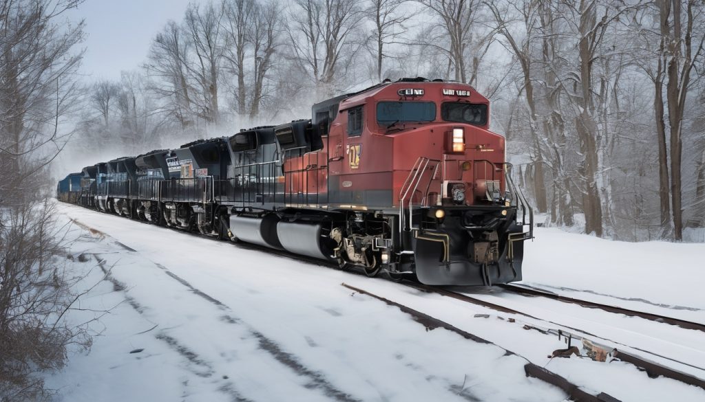
Maintenance leaders ask if a grid box retrofit is feasible and worth it. Aging diesel-electric locomotives face heat, reliability, and control issues that hurt productivity. The main pain point is unplanned failures under dynamic braking or high-grade freight duty. This section gives quick wins to stabilize older locomotives while planning a larger retrofit project.
To ensure safe and efficient operations, focus on verifying key aspects of dynamic brake performance under load. The following steps provide a clear sequence to follow:
- Audit the dynamic brake performance on each locomotive while operating under load.
- Document test results for each unit, noting any deviations or issues identified.
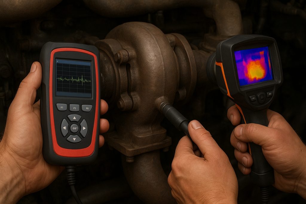
During high-speed shunting, monitor critical components to ensure safety and performance. Specifically, you should:
- Thermograph the grid
- Thermograph the resistor banks
To ensure reliable operation, carry out the following checks:
- Inspect diode racks for cracks.
- Check shunt links for any signs of cracking.
- Examine excitation wiring for cracks.
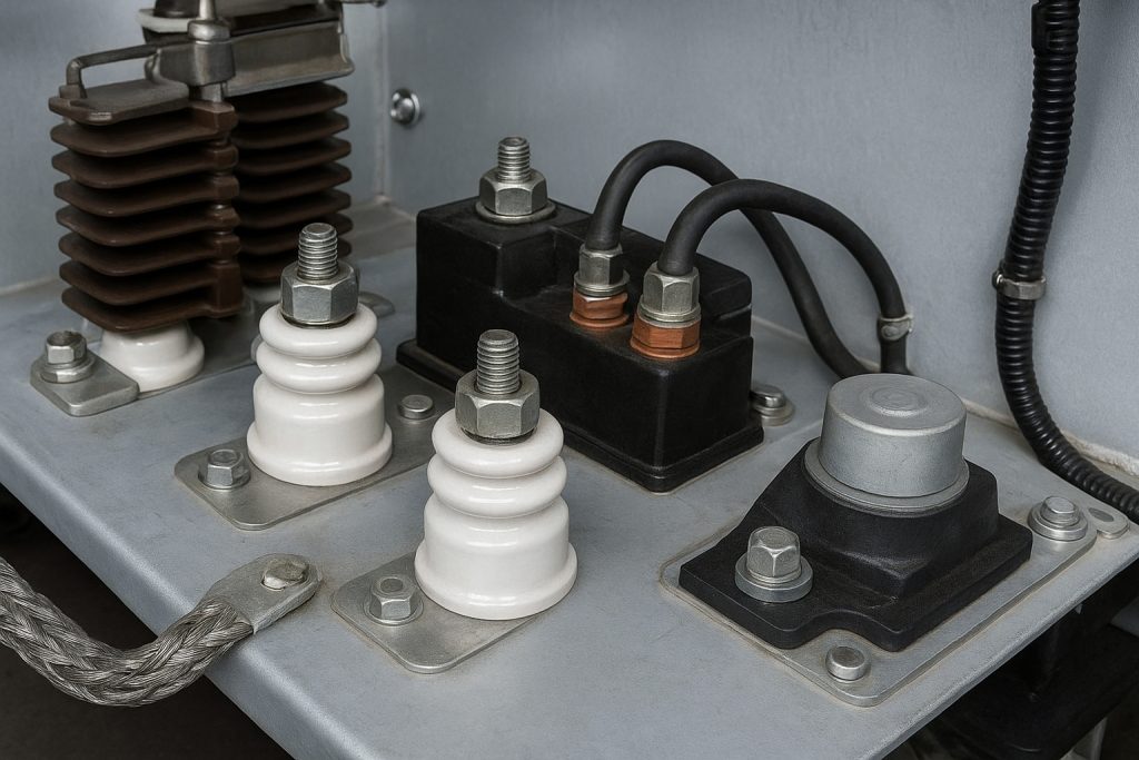
– Clean and retorque high voltage terminals and frames.
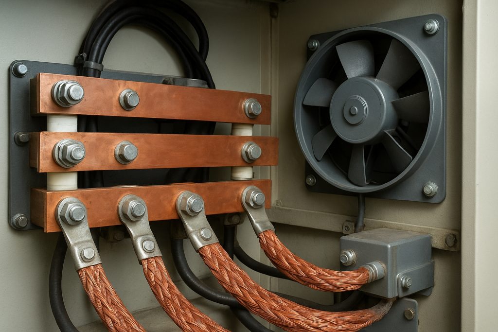
– Upgrade fans and ducts to increase airflow across grids.
– Calibrate throttle-to-brake transition logic in the control system.
– Replace weak contactors and solid state modules proactively.
– Verify cab indications for grid overtemp and wheel slip events.
– Log data from traction motors and alternator during brake tests.
– Establish idle and charge procedures to protect batteries and compressors.
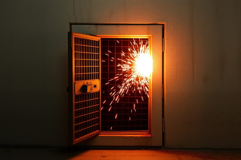
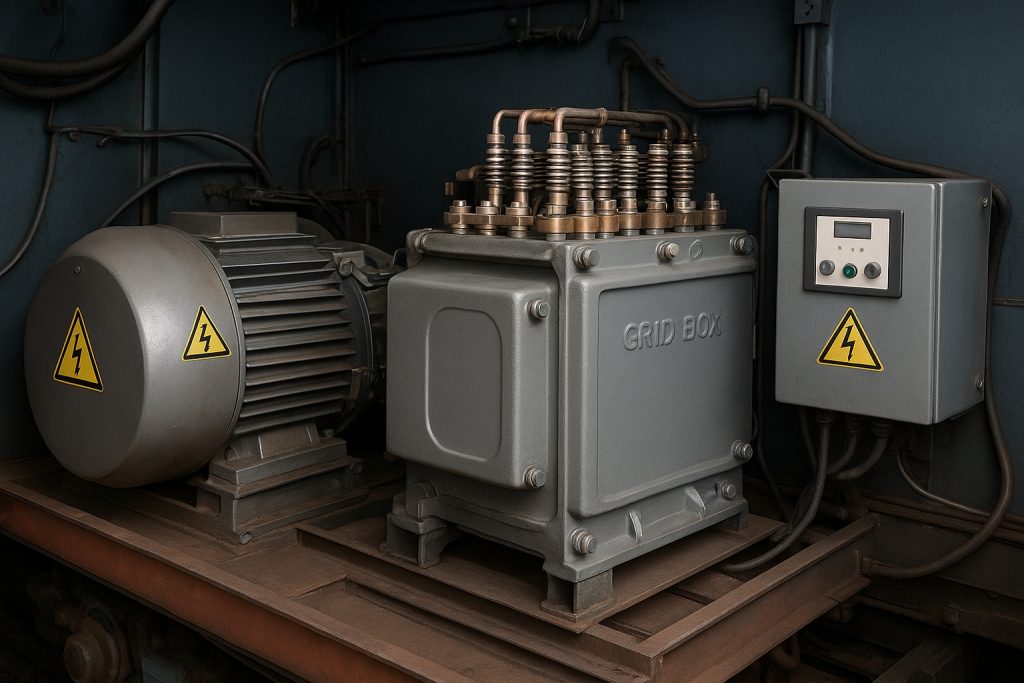
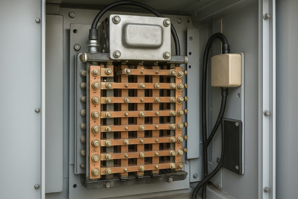
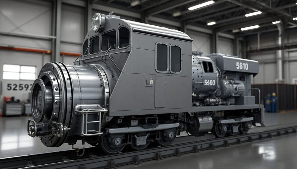
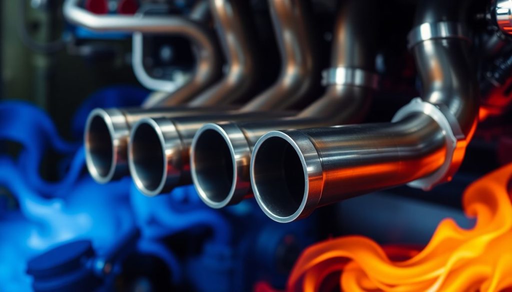
Understanding the Grid Box in Diesel Locomotives

The grid box is the dynamic brake heart of diesel locomotives. During downhill or throttle-off braking, traction motors convert kinetic energy into electrical energy. That energy flows from the generator or alternator through high voltage paths into resistor grids. The grids dissipate heat, allowing controlled braking without air brake wear. In older locomotives, the grid assembly includes resistor elements, blowers, ducts, diode bridges, shunt wiring, and excitation control. The control system modulates current to maintain wheel adhesion on rail. Proper airflow, electrical integrity, and calibration protect the carbody and engine room. A healthy grid reduces brake shoe use, improves reliability, and supports safety and productivity.
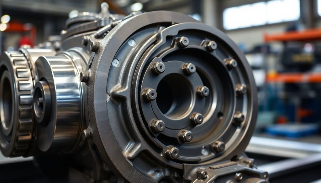
Functionality of the Grid Box
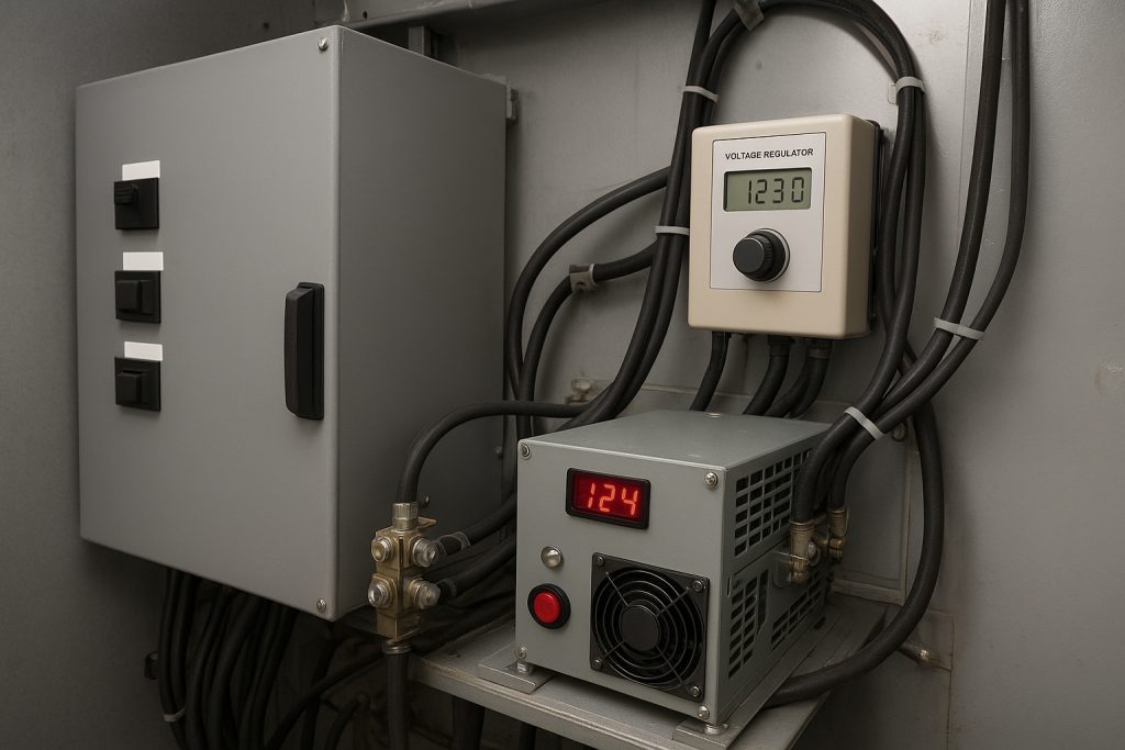
In a diesel-electric locomotive, traction motors act as generators during braking. Their output feeds the grid through contactors and a solid state controller. The resistor stack converts electrical energy into heat, which blowers remove. Voltage and current are balanced to prevent wheel slide on wet rail. The excitation system limits peaks when speed changes rapidly. Diode arrays protect against reverse currents. Shunt circuits adjust braking effort at low speed. Sensors report temperatures to the cab, enabling the crew to manage the throttle and brake lever. Modern upgrades add better airflow, fault logging, and AC traction compatibility for more stable control. The result is stable control, lower environmental impact, and extended fleet service life.
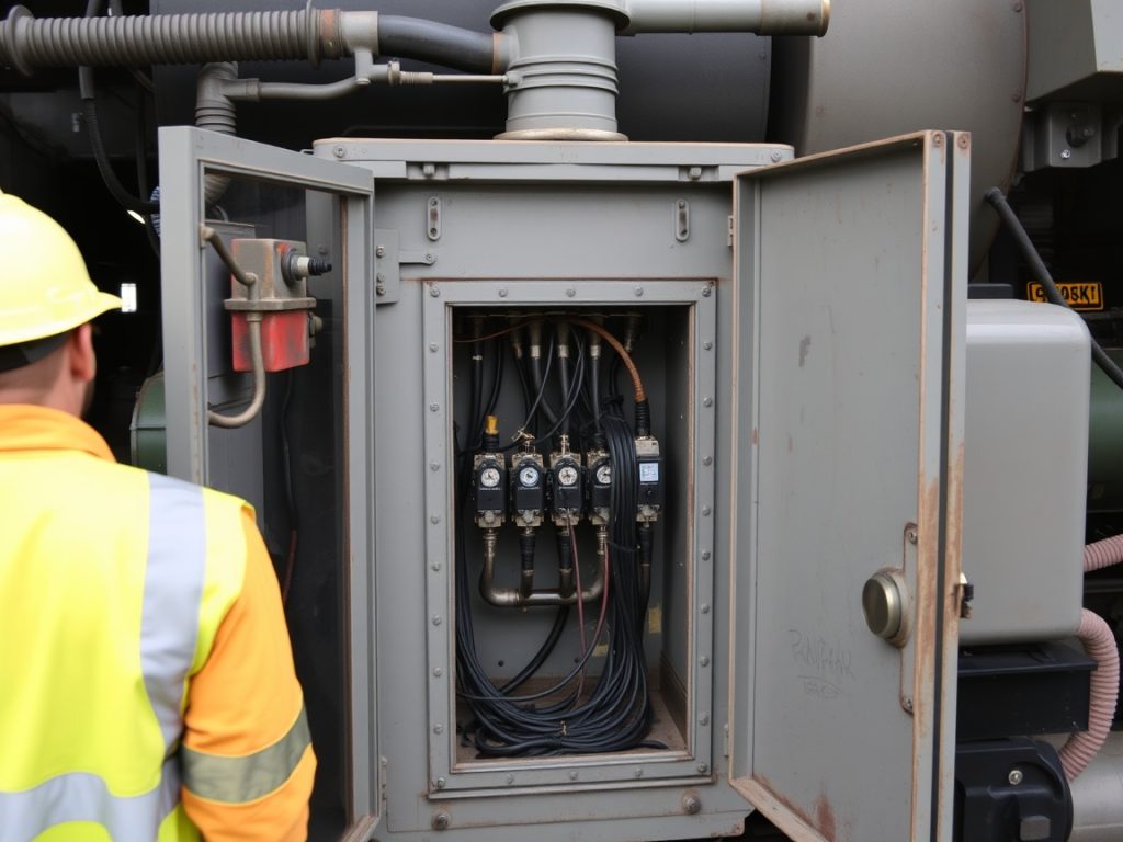
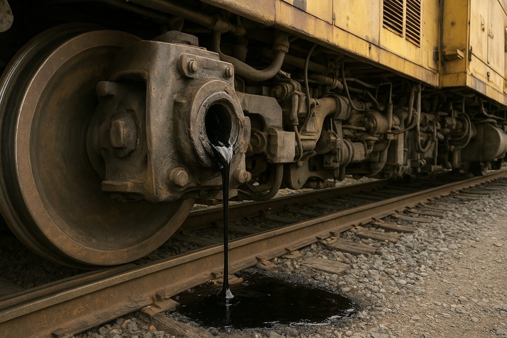
Common Issues with Older Grid Boxes
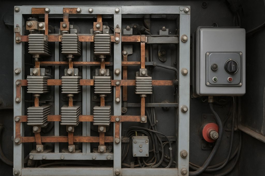
Older locomotives face outdate problems in the grid area. Resistor elements crack, leading to uneven current paths and hotspots. Blowers lose efficiency, so grids overheat and derate. Diode failures cause intermittent braking in dc locos. Wiring insulation in the engine room becomes brittle from heat. Frames and mounts loosen, creating vibration and faults. Solid state cards drift, confusing excitation and shunt control. The cab may show spurious alarms while traction motors see voltage spikes. Airflow ducts clog with dust and oil, and compressors work harder as the air brake compensates. These issues raise downtime and reduce operating margins; timely retrofit can significantly reduce failures in 25-year-old fleets.
Retrofitting Options for Older EMD Locomotives

Most railroad operators fear that an aging grid will fail on a grade. The main pain point is balancing budget and downtime while improving safety. Retrofitting stabilizes dynamic braking and reduces operating risk. Use a phased retrofit project to convert critical components first, then expand. This section outlines practical upgrade paths for diesel-electric locomotives and EMD loco platforms.
– Prioritize thermal management upgrades to protect the grid and frame.
– Replace weak blowers and ducts to increase airflow across resistor banks.
– Add solid state protection for voltage spikes from traction motors.
– Rewire high voltage leads and shunt links with modern insulation.
– Update the control system logic for brake-to-throttle transitions.
– Fit advanced temperature sensors for carbody and grid monitoring.
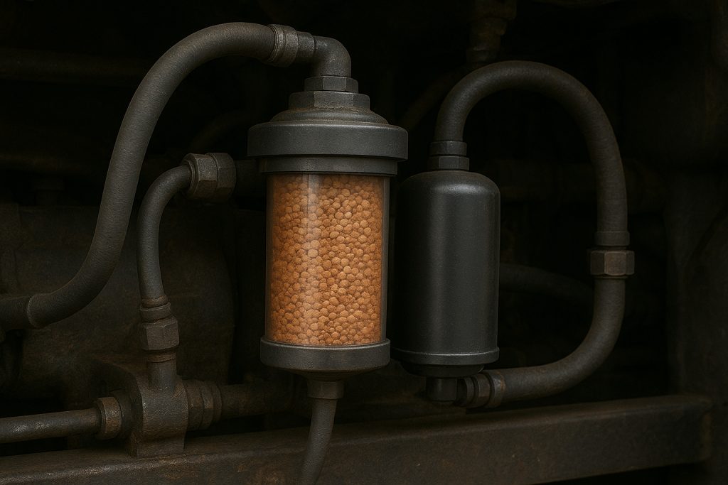
– Use sealed diode modules to improve reliability in dusty engine rooms.
– Calibrate excitation to match alternator and generator characteristics.
– Log data in the cab to validate each modification step.
– Align battery charge and idle policies with new electronics.
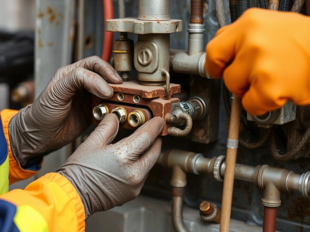
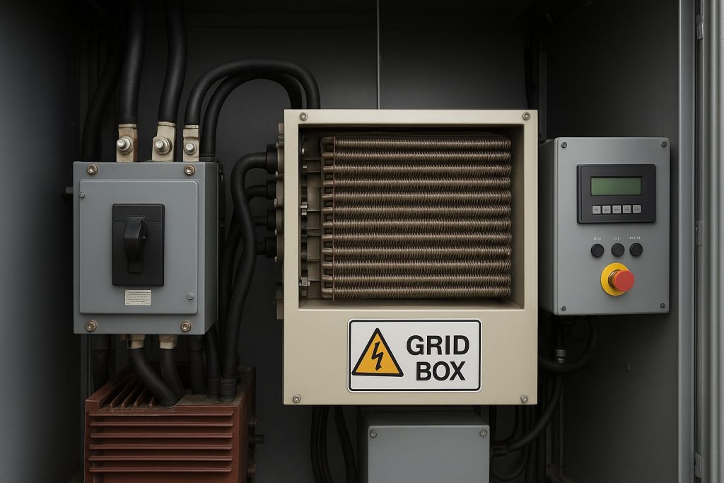
What is Retrofitting?
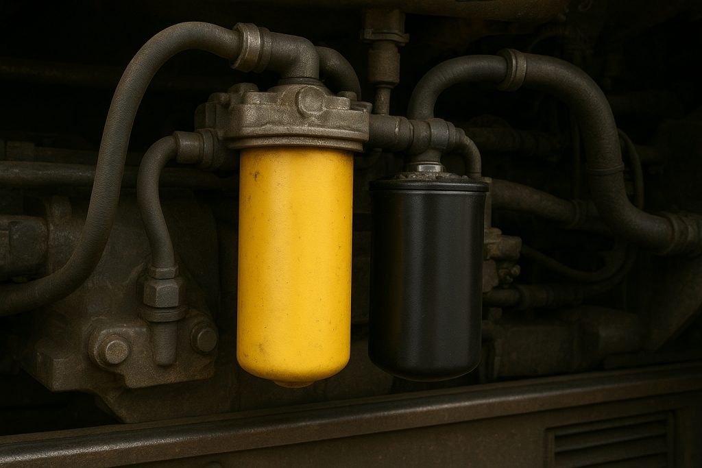
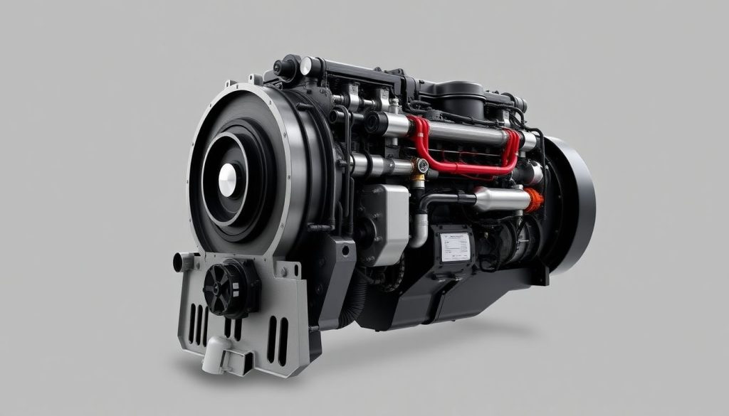
Retrofitting is the targeted modification of a diesel-electric locomotive to extend service life. It replaces or upgrades the grid, blowers, diode racks, shunt wiring, and control system without redesigning the entire chassis. The goal is to reuse structure while inserting new technology focused on the dynamic brake path. It may add ac-compatible modules, improved excitation control, and better thermal sensors. The locomotive’s engine, alternator, and cab wiring are inspected for electrical integrity. Retrofitting can comply with updated railway standards and reduce environmental impact by optimizing braking energy conversion.
Key steps in a retrofit project include baseline testing, component selection, installation, and validation on rail. Baseline and validation on real grades are essential to prove performance and reliability. Component selection compares blower curves, diode ratings, and solid state controller features. Installation addresses mounting on the carbody frame, routing in the engine room, and high voltage clearances. Validation uses repeated downhill runs, throttle transitions, and air brake blending. A good plan will significantly reduce failures in old locomotives without a full conversion to a new locomotive platform.
Benefits of Retrofitting the Grid Box
Upgrading the grid assembly delivers immediate reliability gains. New resistor elements distribute heat evenly, so hotspots shrink and panels last longer. High-efficiency blowers raise airflow, keeping grid voltage and current within safe limits. Solid state modules improve excitation and shunt control during rapid speed changes. Sealed diode packs stabilize dc locos under high-speed braking. The cab gets clearer alarms, helping the crew manage brake effort and throttle. These changes reduce reliance on the air brake, cutting compressor load and wear. Operators see fewer derates on steep rail, better productivity, and safer handling in wet conditions.
Retrofitting also supports compliance and cost control. Modern control systems integrate data logging, so the railroad can audit dynamic braking across the fleet. Smart logic can limit charge draw from the battery, preserve alternator health, and protect the locomotive’s engine. Optional ac traction interfaces enable mixed consists with newer electric motors. Improved wiring and insulation protect the chassis and carbody from heat and vibration. The net effect is reduced downtime, extended asset life, and lower total cost per train-mile. For export-grade parts and kits, Mikura International supplies matched components and technical guidance for EMD retrofit programs.
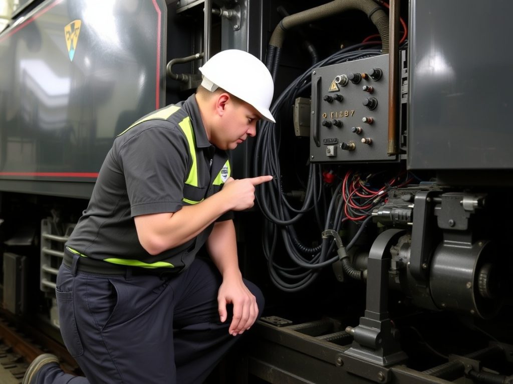
Challenges in Retrofitting Older Loco Models
Older locomotives present integration hurdles that require careful planning. Carbody space is tight, so new blowers and ducts must fit existing frames. Wiring paths in the engine room may not meet today’s high voltage clearance rules. Control system cards can be outdate, making software calibration tricky. Different generator or alternator variants affect excitation tuning. Shunt and diode layouts vary across dc locos, complicating standardization. Some chassis mounts are fatigued, so vibration can damage fresh electronics. Wheel adhesion on worn rail adds uncertainty to test results. Each issue is manageable with a structured engineering review and staged trials.
Supply and documentation gaps add risk. Drawings for an old locomotive may be incomplete, so onsite surveys are essential. Parts interchange between freight, switcher, and passenger variants is not always clean. Emission rules and safety codes change, and the retrofit must comply without a full downgrade of performance. Regenerative braking is often not feasible without a compatible transformer or ac conversion, so expectations must be set. Budget constraints limit scope, making prioritization vital. Early supplier partnership helps align parts, certification, and sequencing to reduce rework.
Upgrading Technology in Older Diesel Locomotives

Older locomotives struggle with heat, unstable brake effort, and outdate control logic. These issues reduce productivity and raise risk on rail. The goal is a retrofit that inserts new technology without a full conversion. Focus on grid, blowers, control system, and wiring inside the engine room. Target the locomotive’s engine interfaces, alternator output, and traction motors. Upgrade paths should reuse the chassis and carbody while boosting reliability. AC traction compatibility can be added with careful excitation changes. A staged retrofit lets operators manage downtime and cost on mixed fleets. Each loco gets measured, modified, and validated under freight and passenger duty.
– Map existing grid wiring, diode paths, and shunt links under high voltage rules.
– Replace resistor elements with high-stability units to reduce hotspots.
– Fit variable-speed blowers tied to grid temperature for better airflow.
– Install solid state protection to guard traction motors and generator.
– Update control system logic for throttle transitions and wheel adhesion.
– Add cab data logging for brake current, voltage, and temperature trends.
– Rewire with modern insulation to protect the frame and chassis.
– Balance battery charge logic to avoid idle overdraw and compressor strain.
– Validate on rail with downhill tests, air brake blending, and high-speed runs.
– Document compliance with railway safety and emission-related electrical standards.
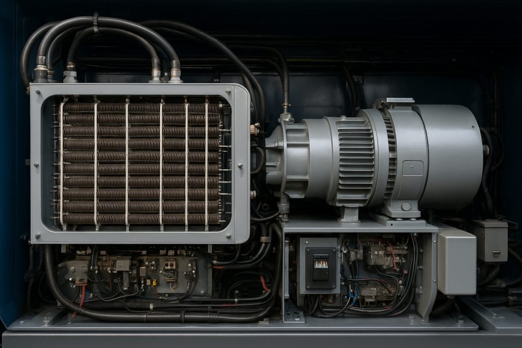
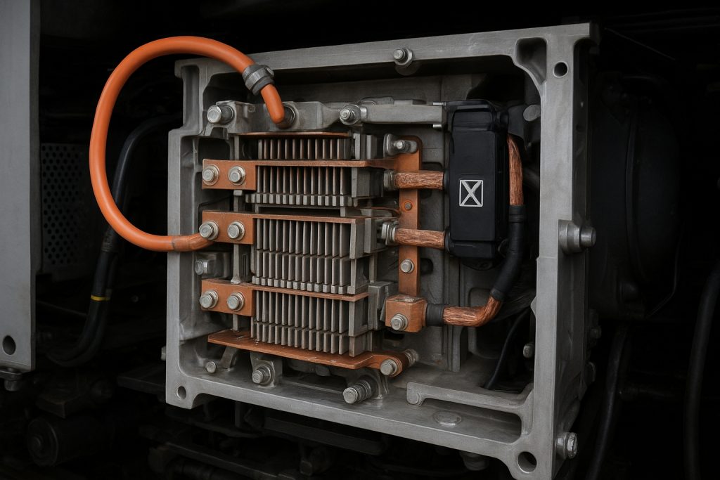
Latest Technologies for Grid Box Upgrades
Modern grid technology lets a diesel-electric locomotive brake harder and cooler. High-dissipation resistor banks distribute heat evenly across the grid. Variable-frequency blowers raise airflow when voltage and current peak. Solid state excitation modules stabilize braking when speed changes. Smart diode modules protect dc locos from reverse currents. Sensors in the engine room stream temperature and vibration into the cab. The control system then tunes shunt and brake effort to maintain traction on wet rail. AC traction-ready interfaces allow consists with electric motors in new locomotives. Edge logging captures brake energy to support maintenance and compliance. These upgrades cut thermal stress and unplanned stops across the fleet.
Comparative Analysis of Upgraded vs. Original Systems
Original systems on old locomotives use fixed-speed blowers and coarse control. Upgraded loco packages deliver precise excitation and airflow. The result is steadier grid voltage, less wheel slip, and longer component life. Resistor life improves, and the frame sees fewer heat cycles. Battery charge is managed, so idle time drops and the compressor runs less. Cab indications become clearer, aiding the crew during freight and passenger moves. Air brake wear falls as dynamic brake carries more load. Operators see fewer derates on long rail grades. The retrofit also prepares for mixed consists with ac traction. Overall, reliability rises and total cost per train-mile trends down.
Cost Considerations for Upgrades
Budget for a retrofit by splitting costs into hardware, labor, testing, and downtime. Hardware includes resistor grids, blowers, diode modules, sensors, and control system cards. Labor covers engine room rewiring, mounting on the carbody, and calibration. Testing includes rail trials for brake current, excitation limits, and wheel adhesion. Downtime planning reduces impact on train schedules. Savings come from reduced failures, lower air brake wear, and lower idle fuel. Avoid a downgrade in performance by matching alternator and generator ratings to the new modules. Plan spares for resistor elements and solid state cards. Mikura International can supply matched kits that comply with railway standards and support predictable installation windows.
Practical Tips for Retrofitting and Upgrading

Unplanned dynamic brake failures in older locomotives hurt timetables and margins. Prioritize grid, control system, and airflow upgrades, and validate under real duty. Use components that comply with railway standards. Align alternator, generator, and excitation to avoid a downgrade. Protect traction motors and battery health. Manage cab indications for the crew. Document voltage, current, and temperature. Prioritize parts with proven reliability.
– Define retrofit scope by failure modes in diesel-electric locomotives.
– Map high voltage paths before any modification work.
– Benchmark brake current and grid temperature on a test train.
– Select resistor, diode, and solid state modules with matched ratings.
– Fit variable airflow to stabilize the grid under high-speed duty.
– Update control system logic for throttle transitions and wheel adhesion.
– Verify battery charge policies to protect the compressor and idle fuel.
– Validate on freight and passenger profiles across wet and dry rail.
– Train crew to interpret cab alarms and data logs.
– Stage the retrofit to reduce downtime while de-risking the fleet.
Step-by-Step Guide to Retrofitting
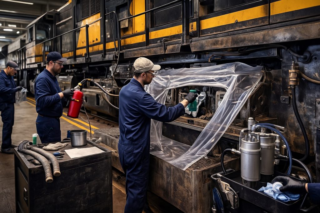
Start with a baseline survey across the fleet of older locomotives. Inspect the carbody, chassis mounts, and frame for heat fatigue near the grid. Record alternator and generator data under brake and throttle transitions. Thermograph resistor banks and ducts at several rail speeds. Next, design the retrofit around reuse of mounts and engine room clearances. Select resistor elements, diode modules, and solid state excitation that match electrical limits. Install variable-speed blowers to control airflow with temperature and voltage. Rewire shunt links with modern insulation for high voltage compliance. Finish with cab calibration, data logging, and downhill validation runs.
Choosing the Right Components for Upgrades
Component selection determines retrofit reliability. Prioritize resistor banks with stable ohmic values at temperature. Choose sealed diode packs for dc locos to prevent dust failures. Specify solid state excitation with fast response to traction changes. Match blower curves to grid dissipation and carbody ducting. Ensure the control system can interface with ac traction if required. Align alternator and generator voltage limits with new modules. Use sensors rated for the engine room environment. Validate connectors for vibration on long freight duty. Confirm software supports wheel slip logic and cab alerts. Select parts that comply with railway codes and emission-related electrical rules.
Expert Insights on Successful Retrofitting
Experienced railroad teams plan around the locomotive’s engine interfaces first.
- They verify excitation behavior during throttle cut and brake onset.
- They protect traction motors with surge limiting and fast shunt control.
- They place temperature sensors near hotspot zones in the grid.
- They log current and voltage at the cab for every trial run.
- They avoid a conversion path that requires a transformer unless ac traction is the goal.
- They stage installations across representative loco variants, including switcher and passenger units.
- They guard against battery abuse during tests and idle.
- They document clear acceptance limits to prevent scope creep.
Keeping spares for resistor and control cards avoids extended downtime.
Future of EMD Locomotive Technologies
Retrofitting the grid and control system extends locomotive life and stabilizes braking. Operators see fewer derates on rail grades and better productivity. Data logs help the crew manage brake and throttle transitions. Air brake wear drops as dynamic brake carries more load. Battery and compressor life improve with smarter charge logic. By reusing the chassis and carbody, capital outlay falls. Reliability gains reduce operating risk across the rr fleet. This path also prepares for optional AC traction interfaces without full conversion. The result is safer trains and stronger margins.
Long-term Benefits of Upgrading
Lower failure rates and predictable maintenance drive long-term value. Balanced voltage and airflow extend resistor life and frame integrity. Smart excitation reduces wheel slip and protects traction motors. Control updates cut spurious cab alarms, helping the crew focus. Battery charge control reduces idle time and compressor cycling. Rail safety improves with stable braking on wet rail. Operators avoid a costly downgrade to performance while meeting compliance. Mixed consists with new locomotives become easier with ac-compatible interfaces. Strategic spares reduce downtime during peak freight windows. These gains compound over years and significantly reduce total cost per train-mile.
Future Trends in Locomotive Technology
Future EMD-oriented upgrades will tighten integration between control system and grid health. Edge analytics will track brake energy and thermal cycles in real time. AC traction support will expand without forcing full conversion. Smarter shunt control will improve adhesion at low speed. Regenerative braking options may emerge with corridor infrastructure, but most fleets will dissipate to grid. Modular solid state racks will simplify swaps in the engine room. Diagnostics will shift to predictive alerts in the cab. More components will comply by design with evolving railway electrical rules. These trends reduce operating risk while sustaining older locomotives.
Final Considerations for Railroad Operators
Define clear retrofit goals and align parts to alternator/generator limits. Approach high voltage changes with strict procedures and audits. Budget for testing time on real rail, not only bench work. Train the crew on cab data and wheel adhesion logic. Plan spares and documentation to sustain the fleet. Avoid overreach, such as transformer-heavy conversion, unless ac traction is mandated. Validate against safety, electrical, and emission-related rules. Use suppliers who guarantee matched kits and technical support. Mikura International provides export-grade components and guidance that shorten installation windows and raise reliability.
FAQ
Q: Can the Grid Box be retrofitted into older EMD locomotives?
A: Yes. Many older EMD models can accept a Grid Box retrofit, but feasibility depends on the specific model, available space, cooling capacity, and the condition of the existing electrical and control systems. A detailed engineering assessment is required to verify mounting, wiring, and integration with the locomotive’s power electronics and safety systems.
Q: What differences arise when retrofitting a Grid Box into a diesel engine-powered EMD versus an electric locomotive?
A: Retrofitting a Grid Box into a diesel-engine EMD primarily involves integration with the prime mover’s alternator/generator, excitation systems, and engine control unit. For an electric locomotive, the retrofit would focus more on compatibility with the high-voltage traction supply and auxiliary converters. Diesel-electrics often require additional cooling and vibration isolation, while electric locomotives may need different insulation and filtering to match system voltages.
Q: How long does a typical Grid Box upgrade take for an older EMD unit?
A: Project duration varies with scope. A basic swap and wiring integration can take a few weeks per locomotive if parts and documentation are available. Complex retrofits involving structural changes, software integration, and extensive testing often take several months. Lead times for parts and testing schedules with regulatory bodies (especially for passenger operators like Amtrak) can extend timelines.
Q: Are there age limits—such as locomotives older than 25 years—where retrofitting becomes impractical?
A: Age alone (for example, 25 years) is not an absolute barrier, but locomotives older than 25 years often present additional challenges: obsolete control electronics, metal fatigue, wiring degradation, and lack of manufacturer documentation. A cost-benefit analysis typically compares retrofit cost against remaining service life and reliability; beyond a certain age, replacement may be more economical.
Q: Will retrofitting a Grid Box improve reliability and performance on Amtrak or commuter fleets?
A: Properly integrated Grid Box retrofits can improve power conditioning, fault tolerance, and control responsiveness, which enhances reliability and can reduce downtime. For passenger operators such as Amtrak and commuter agencies, benefits include better traction control, improved diagnostics, and potentially reduced fuel consumption. Benefits depend on system-level integration and maintenance practices.
Q: What regulatory or certification steps are required for Grid Box retrofits on revenue-service locomotives?
A: Retrofits must comply with applicable national and regional railroad regulatory standards, safety certifications, and sometimes OEM warranties. Passenger carriers like Amtrak may require FRA (or equivalent) approvals, testing protocols, electromagnetic compatibility verification, and documentation of fail-safe behavior. Coordination with inspectors and submitting test reports is typical.
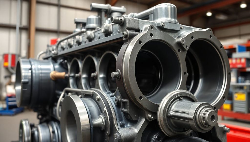
Q: What are the primary technical challenges when installing a Grid Box in an older EMD frame?
A: Key challenges include mechanical mounting and space constraints, thermal management and adequate cooling, electrical compatibility with legacy alternators and control systems, software and communication integration, and ensuring protection against transients and harmonics. Addressing these requires detailed drawings, possible fabrication of adapters, and updated cooling and grounding arrangements.
Q: How should railroads assess whether to retrofit an older EMD locomotive or replace it outright?
A: Railroads should perform a lifecycle cost analysis comparing retrofit costs (parts, engineering, downtime, testing) against acquisition of newer units. Consider asset condition, expected remaining service life, maintenance records, fuel efficiency improvements from the Grid Box, and operational benefits. Include intangible factors such as fleet commonality and regulatory timelines when deciding between retrofit and replacement.