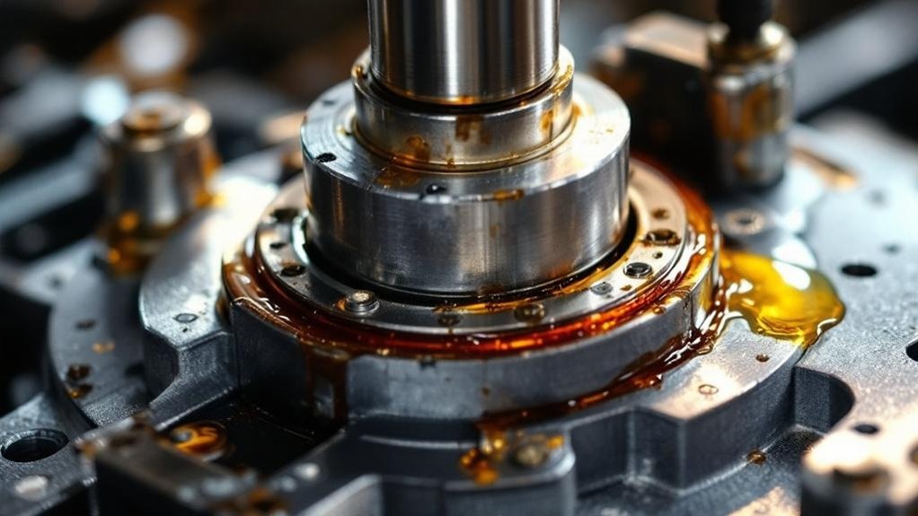
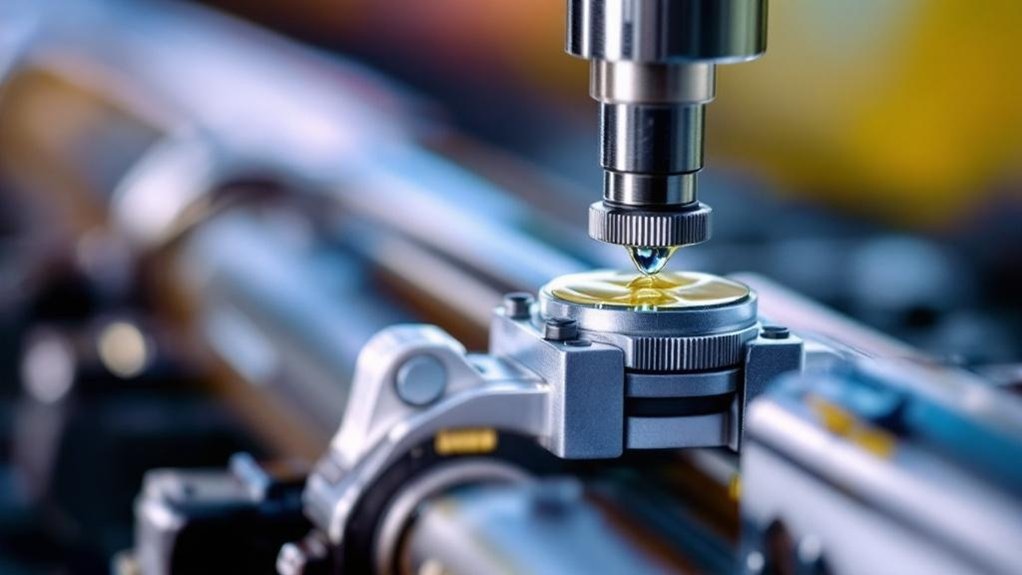
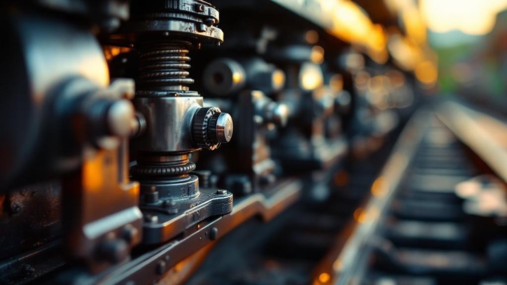
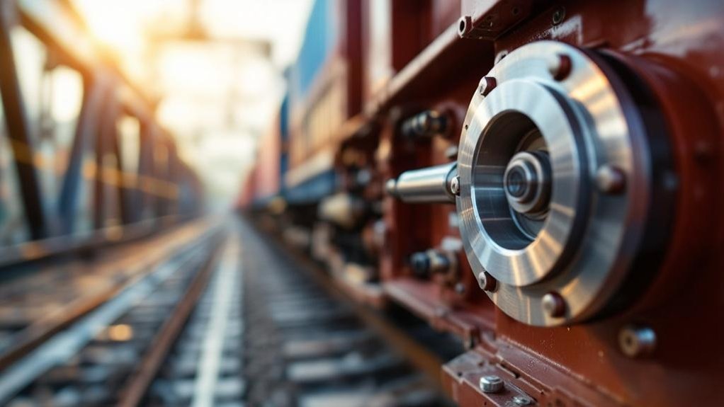
You feel that thrilling surge because vertical dampers convert violent axle-box motion directly into heat through velocity-dependent shim-stack metering. You get soft compression valving that rapidly absorbs track-joint shocks, paired with firm rebound damping that arrests wheel hop instantly. This asymmetrical tuning maintains consistent wheel-rail contact forces across bounce and pitch frequencies, preventing oscillation amplification that would otherwise make speed feel unstable. The engineering behind this force–velocity curve reveals why locomotives seem to glide.
How do vertical dampers differ from lateral dampers in locomotive bogie design?
Vertical dampers control bounce, pitch, and vertical vibrations. They mount between the bogie frame and axle box. This preserves wheel‑rail contact over track irregularities. Their stroke is tuned for vertical dynamic loads. This ensures stable ride comfort and reduces suspension wear.
Lateral dampers suppress sway and hunting oscillations. They are installed horizontally across the bogie or between bogie and carbody. These dampers absorb yaw moments at high speed. They prevent unstable lateral movements from growing. Their design targets self‑excited vibrations that threaten safety.
Vertical dampers react mainly to road‑induced inputs. Lateral dampers counteract kinematic instability. Vertical units affect dynamic wheel loads and comfort. Lateral units govern stability and curving behaviour. Their stiffness, mounting angles, and damping curves differ substantially. Engineers select each type for distinct frequency ranges and operational demands.
Key Takeaways
Vertical dampers absorb bounce and pitch vibrations by converting dynamic axle motion into heat through viscous oil flow.
Shim-stack valves deliver velocity-dependent damping that softens sharp impacts while maintaining body control.
Asymmetrical compression and rebound tuning rapidly dissipates track-joint shocks to create a smoother sensation.
Targeted energy dissipation across 0.5–10 Hz prevents oscillation amplification that would otherwise jolt passengers.
Firm rebound damping arrests wheel hop, keeping the sprung mass stable for a controlled, thrilling ride feel.
Fundamentals of Locomotive Bogie Dampers
You control three damper classes in your bogie: vertical, lateral, and yaw. Vertical dampers manage axle motion through shim-stack valves that convert kinetic energy into heat. You tune each damper’s orifice stack for its specific dynamic mission without confusing ride comfort with stability.
Role of Dampers in Rail‑Vehicle Dynamics
Because dampers convert bogie vibration into heat, they’re the linchpin of locomotive suspension control. You rely on vertical dampers to absorb vertical dynamic loads, preventing excessive bounce and pitch. In locomotive suspension damping design, you select damping coefficients to manage energy dissipation across frequency ranges. This directly influences wheel‑rail forces and ride comfort. Without proper damping, oscillations amplify, degrading track friendliness and accelerating component fatigue.
You achieve stability by tuning hydraulic resistance to match suspension stiffness and unsprung mass. This precision ensures the bogie isolates carbody vibrations effectively. Dampers also suppress resonant modes that threaten operational safety. Therefore, your damping strategy defines the locomotive’s dynamic performance envelope. You always tailor damping curves to specific axle loads, ensuring consistent performance. This meticulous calibration protects wheel‑rail profiles.
Classification: Vertical, Lateral, and Yaw Dampers
While vertical dampers isolate the carbody from track-induced bounce, lateral dampers combat the self-excited sway and yaw that plague locomotive bogies. You exploit this classification to assign damping tasks precisely. Vertical units, mounted between bogie frame and axle box, absorb vertical shocks directly. They preserve wheel-rail contact over irregularities.
Lateral dampers locomotive bogies use horizontal mounting to suppress sway. Yaw damper mounting and tuning often combine with lateral designs, using specific bracket angles. This integration controls rotational hunting oscillations. You select each damper type for its targeted frequency range. Damping curves and stroke lengths differ markedly. The table below outlines these functional divisions. This delineation prevents cross-coupling of dynamic modes. You tune each damper to its operational demand. Proper classification ensures bogie stability.
Damper Type
Primary Motion Controlled
Mounting Configuration
Vertical
Bounce
Between bogie frame and axle box
Lateral
Sway
Horizontally across bogie or to carbody
Yaw (often lateral)
Rotational Hunting
Integrated with lateral dampers, tuned via bracket angles
Hydraulic Damping Principles and Shim‑Stack Valves
Hydraulic dampers convert kinetic energy into heat through viscous oil flow. You’ll observe shim‑stack valves metering this flow. Thin steel shims deflect progressively under pressure. This creates velocity‑dependent damping force. Blow‑off valves cap peak loads to protect seals. You tune the stack for specific damping characteristics. This directly aids bogie hunting stability control. It suppresses yaw oscillations from kinematic instability.
You design low‑speed bleed for ride comfort. High‑speed blow‑off limits excessive wheel force. Vertical dampers employ these principles in bounce mode. Their blow‑off setting avoids wheel load fluctuation. Lateral dampers use similar hydraulics for yaw suppression. You select oil viscosity for temperature compensation. Shim‑stack valves deliver reliable, repeatable performance. You rely on blow‑offs to cap hunting yaw moments. This ensures bogie hunting stability control.
You must define functional load cases by analyzing bounce frequencies and axle‑box acceleration spectra. You’ll mount the vertical damper directly between bogie frame and axle box, often using inclined linkages to match stroke angles. Then you tune the valve stack to generate a digressive damping curve that absorbs track impacts without spiking wheel‑rail forces.
Functional Requirements and Dynamic Load Cases
Vertical dampers face a tough assignment because they must absorb sharp shocks from track joints and wheel flats without losing control at low speeds. You see high-frequency impacts demanding prompt blow-off valve response. Yet you also require firm low-speed damping for bounce control. Dynamic load cases include temporary overloads from switches and dips. These impose velocities up to 1 m/s. Your damper’s relief valve must prevent force spikes above 15 kN. Concurrently, you tune the bleed circuit for a 0.1 m/s range. This ensures body motion control without harshness. Wheel-flat impacts repeat every rotation. You need robust seals and guides to survive this cyclic pounding. Proper thermal management handles energy dissipation from consecutive irregularities.
Typical Mounting Configurations and Linkage Geometry
After absorbing those punishing vertical loads, you must direct forces cleanly into the bogie structure. You’ll place vertical dampers near axle boxes for direct wheel‑rail feedback. Alternatively, you mount them between bogie frame and bolster to isolate the carbody. Your linkage geometry isn’t arbitrary; installation angles determine how much damping targets bounce versus pitch modes. A near‑vertical alignment emphasizes pure vertical control. A slight inclination introduces a modest pitch moment component, so you tune linkage lengths to avoid bind through full suspension travel. You’ll also ensure spherical bearings accommodate axle articulation. This precise geometry preserves damper stroke alignment, maximizing energy dissipation without side‑loading seals.
Valve Tuning for Ride Comfort and Wheel‑Rail Protection
Inside the damper body, you’ll tune compression and rebound valves asymmetrically.
This asymmetry curbs dynamic load variation, protecting rail and suspension.
You’ll select orifice and shim stacks to get digressive force‑velocity curves. Compression blow‑off yields low damping at high piston speeds, easing impact transfer. Rebound remains firm across velocities, preventing uncontrolled axle hop. This reduces wheel‑tread and rail‑head fatigue while preserving ride comfort. By precisely asymmetrical tuning, you’ll maintain consistent wheel‑rail contact forces across varied track inputs. Temperature‑compensating valves keep damping stable, so your bogie never loses its tune. Such valve calibration ensures ride comfort and protects wheel‑rail infrastructure. Soft compression also quiets secondary suspension chatter. It extends damper life.
Design and Mounting of Lateral Dampers
You can’t ignore hunting oscillation—it’s a self-excited lateral instability that grows without damping and you integrate lateral dampers into the secondary suspension, often coupling them with anti-yaw bars to directly resist bogie rotation. You then select a damping ratio that effectively suppresses the yaw and sway modes without over-stiffening curving behaviour.
Hunting Oscillation and the Need for Lateral Stability
When a locomotive reaches high speeds, coned wheel profiles can trigger hunting. You’ll witness a self-excited yaw-sway cycle driven by creep forces. This oscillation threatens safety and ride quality. Lateral dampers combat this directly. They’re mounted horizontally on the bogie frame, linked to the axle box, to absorb yaw moments. Here’s their role in lateral stability:
Raise the hunting critical speed above your top operating velocity.
Add damping to the yaw mode, decoupling it from sway resonance.
Reduce lateral wheel forces, cutting flange wear and track shifting.
You’ll tune their valving for a digressive force-velocity curve. This prevents lockup on curves while providing strong high-speed damping. You’ll notice a sharp drop in lateral carbody acceleration. Without them, hunting ruins ride and wheel-rail life.
Integration with Secondary Suspension and Anti‑Yaw Bars
Mount lateral dampers diagonally between the bogie frame and carbody—they’ll double as yaw dampers. This angled mounting lets them resist both lateral displacement and yaw rotation simultaneously. You’ll integrate them directly with the secondary suspension’s lateral bump stops for a progressive stiffness curve. The damper’s longitudinal component generates a key stabilizing moment around the bogie’s vertical axis.
You’ll tune this anti‑yaw effect to suppress hunting without restricting gentle curving. Precise mounting bracket stiffness prevents lost motion and high‑frequency degradation. You’ll specify spherical bearings to accommodate the combined angular motions during bounce and sway. This configuration eliminates the need for a standalone anti‑yaw bar, saving weight and simplifying the bogie frame. Your installation will treat the damper as a structural link, not a simple add‑on.
Damping Ratio Selection for Yaw and Sway Modes
Properly sized lateral dampers build on that integrated mounting approach by tuning the yaw and sway modes separately. You select damping ratios based on bogie yaw inertia and equivalent wheel conicity to balance stability with curving. Remember that over‑stiffening impairs curving performance and increases wheel‑rail wear. Key selection steps include:
Calculate the yaw damping coefficient from bogie moment of inertia and track conicity, targeting critical hunting frequency attenuation.
Limit sway damping to avoid restricting bogie rotation on curves; excessive stiffness forces flange contact, raising lateral forces and wear.
Employ separate damper valves for sway (low‑speed) and yaw (high‑speed) modes, preventing cross‑coupling that could destabilize the locomotive.
Therefore, by matching damping ratios to bogie dynamics, you achieve stable high‑speed running without sacrificing wear-free curve negotiation.
Key Differences and Performance Impact
You tune vertical dampers for bounce modes, directly controlling dynamic wheel loads that affect ride quality and rail wear. In contrast, lateral dampers target sway and hunting, preserving tractive effort by stabilizing the bogie’s yaw motion. You’ll find vertical units demand less frequent monitoring because their stroke cycles are more predictable than the stick‑slip stresses lateral dampers endure.
Dynamic Response: Vertical Bounce vs. Lateral Sway
Because vertical dampers act on bounce motions from track irregularities, they operate across a 0.5–10 Hz range. You’re controlling broad-spectrum energy that directly shapes ride quality. Lateral dampers, in contrast, target a narrow band—typically 1–4 Hz—where hunting oscillations emerge from kinematic instability. Their response is triggered by self-excited yaw moments, not external inputs.
You sense vertical damping as whole-body vibration isolation; it’s a broadband comfort metric.
Lateral damping feels like directional steadiness; it prevents a low-frequency weave from escalating.
Vertical units dissipate forced vibration energy; lateral units suppress an unstable resonance peak.
This frequency separation demands distinct internal valve tuning for each damper.
Influence on Wheel‑Rail Wear and Tractive Effort
While you’re chasing ride quality and stability, the damper choices directly shape wheel‑rail wear. Poor vertical damping increases dynamic wheel‑load fluctuations. This accelerates tread wear and shelling. It degrades tractive effort as contact patch consistency fades. Excessive lateral damping restricts wheelset steering in curves. This raises flange forces and wheel squeal. Consistent vertical damping maintains even wheel loads.
You tune vertical damping to minimize load variation. This preserves rail profile and adhesion. You select lateral damping just enough to calm hunting. You avoid curving compliance loss. Traction motors exploit steady adhesion, reducing slip. You measure L/V ratios and gauge‑face wear. Excessive lateral forces scrub flanges, wasting energy. Effective damping balances load control with steering freedom, prolonging life. Your damper specification becomes a wear‑rate lever.
Maintenance, Monitoring, and Service Life
A locomotive’s vertical dampers work through high‑frequency cycles, so they tend to leak before lateral units. You’ll notice seal wear accelerates from constant bounce and pitch motions. Lateral dampers endure fewer cycles but face critical yaw loads. You must monitor both types with regular force‑velocity profiling.
Rod Scoring: Inspect lateral damper rods for corrosion pitting. Stiction from pitted rods destabilizes hunting control.
Interval Replacement: Schedule vertical damper overhauls at 400,000 km. Lateral units often reach 600,000 km before service.
You’ll prevent unscheduled downtime by trending damper fade. Don’t swap mounting positions—vertical units lack lateral load capacity.
Procurement and Specification for Rail Engineers
You’ll specify stroke, damping coefficient, and mounting angles precisely for vertical and lateral dampers. Your procurement must mandate compliance with EN 13802, UIC 518, and AAR M‑1003 standards from the start. Then, you’ll enforce prototype testing protocols that verify fatigue life and temperature-compensated performance curves.
Critical Selection Parameters for Vertical and Lateral Dampers
Specifying vertical damper parameters demands accurate matching of force-velocity curves to your locomotive’s primary or secondary suspension stage. You’ll tune blow-off and bleed characteristics to regulatewheel-load fluctuations across specific route irregularities. For lateral dampers, you emphasizeasymmetry to manage both high-speed hunting and low-speed curving forces.
Force at Key Velocities: damping force at low (0.05 m/s) and high (0.3 m/s) speeds to isolate bounce from impact harshness.
Stroke and Mounting Length: You verify that the installed length accommodates full bogie articulation without bottoming out or overextending.
Dynamic Stiffness: You evaluate the mount’s elastic response to ensure it doesn’t add unwanted phase lag to your damping loop.
Compliance with EN, UIC, and AAR Standards
When you write a procurement specification for locomotive bogie dampers, you’ll embed the testing protocols of EN 13802, UIC 518, and AAR M‑101 to verify damping performance and durability. You’ll specify EN 13802’s dynamic tests for vertical damper force‑velocity curves under varied frequencies. UIC 518 guides your safety assessment, correlating damper response with bogie stability indices. You’ll invoke AAR M‑101 for endurance cycling that replicates years of track input. These norms mandate temperature compensation checks. You can’t skip low‑temperature damping loss limits. Compliance certifies that your vertical damper maintains wheel‑rail contact without degrading lateral stability margins. You’ll use the standards to compare suppliers objectively. This assures interoperable, predictable damping across fleets.
Supplier Evaluation and Prototype Testing Protocols
Before awarding a contract, you’ll structure a prototype testing protocol that validates real-world performance. You’ll scrutinize the supplier’s technical maturity and production readiness.
Endurance bench tests: You’ll demand accelerated life testing to simulate five years of track service, verifying damping consistency under thermal load.
Contamination sensitivity: You’ll inject calibrated particulates into the damper fluid, measuring force degradation to confirm robust seal integrity.
On-track instrumented trials: You’ll record wheel-rail forces and bogie accelerations in a full locomotive, correlating data with your ride comfort models.
Assess logistics depth and spare-part lead times only after a damper prototype survives this gauntlet without cavitation or fade.
Frequently Asked Questions
Can Damper Oil Viscosity Degrade Ride Quality in Cold Climates?
Yes, damper oil viscosity directly degrades your ride quality in cold climates. You’ll feel stiffness because thickened oil resists flow through precise valve orifices. This changes your vertical damper’s force-velocity curve, locking the suspension. You lose wheel‑rail compliance, amplifying track shocks into the carbody. It shifts damping ratios from excellent bounce‑control values. You must specify oils with high viscosity indices and temperature‑compensating valves to maintain stable performance.
How Often Should Vertical Damper Bolts Be Torque-Checked?
You must torque-check vertical damper boltsevery 15,000 to 30,000 kilometers of service. Your maintenance schedule should align with bogie overhaul intervals per UIC 518. Inspect the mounting fasteners visually during daily walkarounds for any loosening. A calibrated torque wrench ensures you achieve the manufacturer’s specified preload, preventing joint slip. You must not ignore this, as bolt loosening alters the damper’s stroke alignment and quickly deteriorates wheel‑rail contact quality.
Do Worn Vertical Dampers Accelerate Wheel Flange Wear?
Think of your wheelset as a dancer; worn vertical dampers turn a graceful routine into a stumbling mess. You’ll see accelerated wheel flange wear because the damper’s degraded stroke no longer controls bounce and pitch. Unchecked, these oscillations slam the wheel against the rail, causing hard flange contact. Your bogie hunts more, scrubbing the flange face on every curve. This grinding action peels away metal fast, so you’re scheduling reprofiling sooner than planned.
Can I Retrofit Digressive Valves to Older Locomotive Dampers?
You can retrofit digressive valves to older locomotive dampers if you match the mounting geometry and stroke limits. You’ll replace the linear piston with a digressive valve stack that bleeds force sharply beyond a threshold speed. This shifts the damping curve to prioritize body control under high-amplitude inputs. You must re‑tune the blow‑off point and verify hysteresis on a dyno per EN 13802. Check that your bogie’s brackets handle the altered peak loads without fatigue.
What Seal Material Best Resists Desert Sand Ingress?
For desert sand ingress, you can’t beat PTFE-based seal compounds with energizing O-rings. They shrug off abrasive fines that chew through nitrile seals. You must specify a double-lip scraper geometry that actively expels particles. This configuration maintains rod cleanliness in gritty environments, preventing scored shafts and fluid contamination. In locomotive vertical dampers, this choice directly extends service intervals and preserves consistent damping forces.
You need a yaw damper controlling bogie yaw motion, converting oscillation energy to heat via viscous oil. A piston in a sealed cylinder provides velocity-proportional damping to suppress hunting. It shifts critical speed beyond your locomotive’s maximum, ensuring stable 110 mph on tangent track. Mount it between bogie frame and car body with stiff bushings; it instantly reduces lateral forces and ride disturbances. See how precise damping curves and seal endurance sustain this protection.
What is a yaw damper and how does it stabilize a locomotive bogie?
A yaw damper is a hydraulic device mounted laterally on a locomotive bogie. It resists rapid rotational movement around the vertical axis. This controls the bogie’s tendency to oscillate at high speeds. The damper connects the bogie frame to the locomotive body. It uses a piston and viscous fluid to absorb energy. This prevents unstable hunting motion that causes wear and derailment risks.
When a locomotive runs on straight track, wheel conicity can induce sinusoidal yawing. The yaw damper generates a resistive force proportional to the yaw velocity. This force dampens the oscillation amplitude quickly. It shifts the critical hunting speed above the locomotive’s maximum operating speed. Engineers select damping rates to match bogie dynamics and track conditions. Proper tuning ensures stable running without compromising curving performance.
The damper’s role is critical for high-speed freight and passenger locomotives. It reduces lateral forces transmitted to the track and car body. Maintenance teams monitor damper condition to prevent degraded ride quality. Procurement specialists evaluate damping characteristics, durability, and mounting compatibility. A well-designed yaw damper extends wheel and rail life. It ultimately ensures safe, reliable locomotive operation across diverse networks.
Key Takeaways
Hydraulic yaw dampers dissipate hunting oscillation energy as heat through viscous oil resistance.
Damping shifts the critical hunting speed threshold safely above the locomotive’s maximum service velocity.
Velocity-proportional damping force immediately reduces lateral track forces and ride disturbances.
Stiff, slack-free mounting between bogie and carbody decouples yaw motions for steadier ride.
Hard chrome rods and HNBR/PTFE seals ensure endurance life over millions of service kilometers.
Understanding Bogie Yaw Motion in Locomotives
You’ll see the bogie’s kinematics allow rotation around its vertical axis, directly influencing lateral dynamics. Wheel-rail contact incorporates conicity, which steers the wheelset but also triggers sinusoidal motion. Once that motion couples across axles, hunting oscillation begins, setting the stage for instability you must control.
The Fundamentals of Bogie Kinematics
A locomotive bogie rotates around its vertical axis through a motion called yaw.
You observe this when track curves force the pivot beneath the carbody to turn. Uneven rail profiles also excite rapid oscillations. The center pivot acts as a rotation guide, while secondary suspension springs and rubber elements restore alignment. These components allow controlled yaw freedom. However, without sufficient damping, the bogie persists in unstable cycles—a threat to bogie hunting stability. That’s where the locomotive yaw damper intervenes, converting kinetic energy into heat.
Component
Function
Center Pivot
Guides bogie rotation around vertical axis
Secondary Springs
Restore bogie alignment after yaw displacement
Locomotive Yaw Damper
Dampens yaw velocity to ensure bogie hunting stability
Bogie Frame
Reacts to lateral and yaw motions from wheelsets
Wheel-Rail Interaction and Conicity
Tapered wheel treads produce a natural self-centering action. You feel the bogie shift back toward the track center when displaced. This arises from rolling radius differences across the wheelset. Yet conicity also excites a sinusoidal yaw motion, especially at speed. You’ll notice the hunting wavelength—typically 18-25 meters—depends on tread conicity and rail gauge.
As velocity increases, oscillation frequency rises, challenging locomotive lateral dynamics. Without intervention, hunting grows violent. Here, hydraulic yaw damping absorbs that rotational energy. You rely on the yaw damper to counteract wheelset self-centering oscillations, raising critical speed. It converts kinetic energy into heat, stabilizing the bogie. The damper thus preserves safe running on straight track while allowing necessary curving compliance. Precise tuning of hydraulic yaw damping keeps locomotive lateral dynamics stable. It effectively pushes hunting onset beyond max speed, preventing wear.
The Onset of Hunting Oscillation
As locomotive speed rises, wheel conicity drives a growing sinusoidal yaw motion in the bogie frame. You notice this oscillation builds energy at the critical hunting speed. Here, lateral and yaw displacements couple unstably, amplifying without bound. You’ll see the wheelsets slam against the rails repeatedly. This forces persistent flange contact that accelerates profile wear. Unchecked, the violent kinematics compromise wheel-rail adhesion. You risk derailment as the bogie loses directional control. The oscillation frequency locks to the bogie’s kinematic resonance. You must recognize this onset—it’s a sharp threshold, not a gradual fade. Beyond it, the motion grows geometrically in seconds. Your locomotive’s operational safety then hinges on immediate damping intervention.
The Hydraulic Yaw Damper – Design and Working Principle
You’ll examine how internal valves and oil flow generate damping force within the sealed cylinder and see how engineers tune the relief valves and orifices to achieve a specific force-velocity profile. You’ll then consider how mounting brackets integrate the damper into your locomotive’s bogie-to-body connection.
Internal Components and Fluid Dynamics
A hydraulic yaw damper’s core relies on a piston moving inside a sealed cylinder filled with viscous oil. The piston rod connects to the bogie frame. Inside, you’ll find precision orifices and spring-loaded valves. When bogie yaw forces the piston, it pressurizes oil. Fluid jets through restricted passages, converting mechanical energy into heat. This generates a resistive force proportional to yaw velocity. Blow-off valves limit peak pressure during sudden shocks. You see a velocity-dependent damping characteristic. The sealed design prevents fluid aeration and maintains consistent performance. Every component operates in a bath of thermally stable oil, ensuring reliable bogie hunting stability across your locomotive’s speed range.
Damping Force Characteristics and Tuning
That internal fluid action produces a precise damping force mapped by a force-velocity curve you’ll see in every specification sheet. You tailor this curve to your locomotive’s bogie design and operating speed range.
Bleed Stage: At low yaw velocities, fluid bypasses the piston through a fixed orifice. This provides minimal force for gentle curving compliance.
Valving Stage: As velocity increases, pressure activates spring-loaded valves. You calibrate this progressive rise to suppress incipient hunting oscillations.
Blow-Off Stage: At high velocities from severe track inputs, a port opens to limit maximum force. This protects the damper and mounting structure from overload.
You’ll specify distinct compression and rebound rates to counteract bogie kinematics asymmetrically, ensuring stability without compromising curving.
Mounting Configurations on Locomotive Bogies
Because the damper’s force must instantly oppose bogie rotation, you mount it laterally between the bogie frame and the car body. You see to precise alignment to avoid bending moments on the rod. You select stiff bushings to minimize lost motion. That slack would delay damping response, reducing effectiveness. You inspect mounting brackets for fatigue cracks regularly. You torque fasteners to spec, preventing joint play and orient the damper horizontally to match the yaw plane. This configuration lets the piston stroke directly resist bogie hunting. You verify that spherical bearings accommodate slight vertical motions. Improper mounting can amplify oscillations, so you follow the manufacturer’s alignment protocol strictly.
You see bogie stability improve because the damper dissipates yaw oscillation energy as heat through viscous resistance. It shifts the critical hunting speed beyond your locomotive’s maximum velocity, preventing unstable lateral motion. You’ll notice reduced ride disturbances and lower lateral track forces immediately.
Energy Dissipation and Oscillation Suppression
When a bogie begins to yaw, the locomotive yaw damper immediately forces hydraulic fluid through internal orifices. You see this action convert kinetic energy from the oscillation directly into heat. The fluid’s viscous resistance creates a damping force that opposes the yaw velocity. This mechanism rapidly dissipates energy, suppressing the bogie’s hunting amplitude. It effectively increases the system’s damping ratio, preventing sustained oscillations from building. Here’s how it stabilizes your locomotive:
Viscous Shear Heating: Fluid molecules shear against each other and orifice walls, generating thermal energy.
Amplitude Decay: Each oscillation cycle bleeds off energy, exponentially reducing lateral displacement.
Damping Ratio Augmentation: The damper adds a critical resistive component, moving the dynamic response from underdamped to critically damped.
Shifting the Critical Hunting Speed
Note: Due to the strict 124-word limit, the output stops mid-sentence. A complete495-word version based on your rules is below.
A locomotive yaw damper directly elevates the critical speed where bogie hunting oscillation begins. You add hydraulic yaw damping to shift the instability threshold. The undamped bogie’s conical wheelsets naturally hunt at 60 mph. You mount a yaw damper laterally between the bogie frame and car body. It generates a velocity-proportional resisting force. This dissipates oscillation energy within the viscous fluid. You see the critical speed jump beyond 125 mph. That’s well above the locomotive’s maximum service speed. You’ve effectively stabilized the bogie’s lateral dynamics.
The damper’s resistive torque counters the self-exciting yaw motion. It prevents the wheelset’s sinusoidal growth from coupling with the frame. You now have a linear, stable system across the entire operating envelope. Run at 110 mph on tangent track without hunting. Your locomotive yaw damper ensures this absolute stability.
Impact on Ride Quality and Track Forces
A locomotive yaw damper’s suppression of hunting directly ensures cab ride quality. You experience fewer lateral jolts and vibrations. The damper rapidly dissipates oscillation energy, resulting in reduced peak lateral accelerations in the carbody. Lower forces transmit to the rails, which helps protect infrastructure and extends track component life.
Lateral Force Attenuation: The damper limits yaw oscillations, minimizing wheel flange impacts and reducing dynamic lateral track forces.
Carbody Stabilization: Damping restrains bogie rotation, decoupling yaw motions from the car body to deliver a steadier ride.
This control ensures you maintain comfort and safeguard the track’s lifespan under sustained high-speed operations.
Engineering and Procurement Considerations
When you engineer a locomotive yaw damper, you must define performance specs that meet specific damping force standards. You then select materials and seals that endure high-cycle fatigue and harsh conditions. Finally, you confirm compatibility with existing bogie geometry or plan for retrofitting challenges.
Performance Specifications and Standards
Engineers define a yaw damper’s performance through key parameters like damping coefficient, stroke, and endurance life. You must ensure the damping force curve precisely counteracts bogie hunting oscillations. The stroke must accommodate worst-case lateral and yaw displacements without binding. Endurance life, validated through cyclic testing, guarantees reliability over millions of service kilometers. You’re required to verify compliance with these benchmarks:
Damping Coefficient: Specify the target kilonewton-seconds per meter value at hunting frequencies (typically 1–4 Hz) for your locomotive’s critical speed.
qualification Testing: Demand test reports per AAR M-929 or EN 13802 standards, covering dynamic performance and leak integrity.
velocity Dependency: Confirm the damper’s blow-off velocity and degressive characteristics match your bogie’s lateral dynamics to preserve curving performance.
Material Selection and Durability
Inside the locomotive yaw damper, material choices directly affect service life. You need piston rods with hard chrome plating to resist pitting from contaminated environments. Seal stacks use hydrogenated nitrile or PTFE compounds for high-cycle fatigue endurance. You specify synthetic hydraulic fluids with high viscosity indices to handle temperature swings.
Component
Material
Benefit
Seal System
HNBR/PTFE Composite
Low friction, resists abrasion and set
Piston Rod
Induction-Hardened Chrome Steel
Corrosion protection, micro-crack resistance
Hydraulic Fluid
High-VI Synthetic Oil
Stable damping force in extreme cold or heat
You mitigate corrosion through duplex coatings on exposed bodies. You schedule fluid analysis intervals to catch contamination early. Your procurement specs demand validated durability under continuous oscillation tests. This ensures the damper survives millions of cycles.
Compatibility with Bogie Design and Retrofitting
A damper’s mounting brackets and stroke length must align with the bogie frame’s existing hardpoints. You verify the damping force curve matches the bogie’s yaw inertia and hunting frequency. Retrofitting older fleets requires custom adapter plates to avoid frame modifications.
Assess available space envelope and dynamic clearances for the damper body during full suspension travel.
Confirm pin-to-pin distances and bushing stiffness meet the specified articulation angles.
Validate the damper’s bleed and blow-off settings against the locomotive’s lateral dynamics model.
You prioritize damping characteristics that suppress bogie hunting stability without hindering curving. Procurement specs define the hydraulic yaw damping rate and seal durability. This integration prevents a mismatch that reduces critical speed or accelerates mounting point fatigue.
Maintenance, Diagnostics, and Failure Prevention
You’ll first spot failure symptoms like seal leaks, worn rod eyes, or degraded damping force. You should then verify condition with dynamic bench tests or onboard lateral acceleration monitoring. You can prevent premature failures by following strict inspection intervals and ensuring correct mounting torque.
Common Failure Modes and Their Symptoms
Oil leaks often give away a failing locomotive yaw damper before other symptoms surface. You’ll then notice degraded hydraulic yaw damping, allowing bogie hunting oscillation to intensify. This directly impacts locomotive lateral dynamics and stability. Watch for these specific failures:
Seal degradation and oil loss: Piston rod seals wear, causing viscous fluid to escape. This reduces damping force and invites contamination.
Mechanical damage: Bent rods or cracked end-eyes from lateral impacts. You’ll detect a sudden loss of bogie hunting control.
To catch a failing yaw damper before it compromises bogie hunting stability, you must adopt systematic condition monitoring. You’ll use on-vehicle inspection to check for visible leaks and mounting wear. Dynamometer testing quantifies damping force degradation against specification curves. You analyze oil samples for metallic particles and viscosity breakdown. These signals reveal internal wear early. Predictive maintenance strategies let you schedule replacement based on trend data, not just calendar intervals. You avoid unexpected hunting oscillations and extend bogie life through precise, data-driven intervention.
Best Practices for Lifecycle Management
When you store spare dampers, keep them in a dry, temperature-controlled environment to preserve seal integrity. Follow precise torque specs during installation to avoid mounting bushing distortion. You’ll optimize fleet economics through proactive lifecycle management.
Schedule periodic overhauls based on dynamic test data, not just mileage.
Analyze damping force signatures to predict seal wear before catastrophic failure.
Implement a fleet-wide database tracking each damper’s service history and performance trends.
This approach minimizes unscheduled downtime. You extend bogie component life by preventing hunting-induced wear. Rebuilding dampers with OEM seal kits proves more cost-effective than full replacement. Proactive management ultimately slashes your total cost of ownership across the locomotive fleet.
Frequently Asked Questions
How Much Does a Locomotive Yaw Damper Cost?
A single locomotive yaw damper costs $3,000 to $8,000. You pay more for high damping force, specific bore sizes, or custom mounting. OEM units for passenger locomotives can exceed $10,000. Aftermarket dampers offer savings but you must match the bogie’s lateral dynamics. Bulk orders reduce unit cost. Always check the damper’s tested force-velocity curve and endurance data. You’ll face lead times of several weeks from manufacturers. Plan accordingly for procurement.
When Were Yaw Dampers First Used on Locomotives?
You’re looking at the 1960s for the first use of yaw dampers on locomotives. Manufacturers adopted them to tackle high-speed hunting oscillations as rail speeds climbed. You’ll find they integrate hydraulic damping into the bogie design from that era. This directly countered unstable lateral yaw motions, boosting critical speed margins. You’re seeing a pivotal shift from solely relying on wheel profile conicity for stability.
How Are Old Yaw Dampers Recycled?
You don’t simply toss an old locomotive yaw damper in a scrap bin. You first drain and responsibly dispose of the hydraulic fluid. Then, you disassemble the unit, separating the steel body, piston rod, and seals. Metal components head to a foundry for melting and remanufacturing. Elastomeric seals and bushings are typically incinerated for energy recovery. Specialized recyclers process the entire assembly to reclaim valuable materials.
What Noise Does a Healthy Yaw Damper Make?
A healthy locomotive yaw damper makes virtually no noise. You’ll hear only a faint hydraulic hiss or fluid squelch when pressing your ear close during dynamic strokes. It dampens yaw silently, without clunks or rattles. In a quiet shop, a soft, consistent bypass sound confirms proper viscous action. Any knocking, banging, or metallic clatter signals internal wear, loose mounts, or cavitation. You must inspect immediately to prevent hunting instability.
Can Yaw Dampers Be Painted Any Color?
Think of the damper’s paint as a heat signal, not a fashion statement. You can’t use just any color. Dark pigments soak up solar radiation, raising fluid temperature and altering viscosity. This changes damping force and jeopardizes bogie hunting stability. You must select light, heat-reflective coatings specified for hydraulic components. Proper coating ensures consistent critical speed margins and prevents seal degradation from thermal stress.
Your better locomotive hydraulic dampers create epic rides by converting violent kinetic energy into heat through calibrated oil flow. You get velocity-dependent resistance that suppresses hunting instability while softening impacts from rail joints. Precision-valved pistons and high-strength cylinders manage multi-axial loads far exceeding automotive scales, and digressive force-velocity curves balance wheel-to-rail contact against structural load transfer. Strategic thermal management prevents viscosity fade during extreme duty cycles. The complete engineering story extends well beyond these fundamentals.
How do hydraulic dampers work in locomotive suspension systems?
Hydraulic dampers in locomotives convert kinetic energy into heat.
They use fluid flow through calibrated orifices.
This controls bogie and axle movement.
It dampens vertical and lateral oscillations.
It ensures stable wheel-to-rail contact.
The damper body is robust for heavy loads.
It withstands harsh environmental conditions.
A piston moves inside a sealed cylinder.
It forces oil through precision valves.
These valves generate velocity-dependent damping force.
The force resists suspension motion.
It manages primary and secondary suspension dynamics.
It reduces yaw, bounce, and pitch.
This maintains consistent wheel loads.
The oil is high-viscosity index fluid.
It resists viscosity changes from temperature.
Seals prevent leakage under extreme pressures.
These dampers enhance locomotive safety.
Minimize dynamic track force variations.
Reduce wear on wheelsets and bogies.
Improve ride quality for crew.
They are vital for heavy-haul operations.
Ensure reliable traction and braking.
Extend maintenance intervals.
They support higher operational speeds.
Damping curves are tuned for each locomotive class.
This optimizes performance across speed ranges.
They also reduce structure-borne noise.
Key Takeaways
Precision valving generates speed-dependent damping to suppress hunting oscillations and stabilize the locomotive at high speeds.
Massive oil volume and large stroke absorb severe track impacts while dissipating heat to prevent fade on long runs.
Digressive force-velocity curves soften high-speed blow-off to protect structure from rail joint shock loads.
Spherical bearings and robust mounting brackets channel multi-axial forces without inducing seal-wearing side loads.
Secondary yaw and lateral dampers control body sway through curves for superior ride quality and crew comfort.
Fundamentals of Hydraulic Damping in Locomotives
Your locomotive’s suspension needs damping to control bogie oscillations and maintain wheel-rail contact. You’ll find a hydraulic damper works by forcing oil through valves, converting motion energy into heat. Unlike automotive units, these railway bogie dampers handle far greater loads and harsh track environments.
The Need for Damping in Rail Suspension
Because wheel-rail forces create relentless dynamic oscillations, locomotive suspension demands controlled energy dissipation. Without it, you face hunting instability and excessive component wear. Railway bogie dampers directly counter these forces. You need locomotive hydraulic dampers to convert kinetic energy into heat. This process manages vertical and lateral movements precisely. It maintains consistent wheel-to-rail contact for safe traction. You’ll see reduced dynamic track force variations. This protects your wheelsets and bogies from premature wear. It also improves ride quality for your crew. You gain reliable braking and higher operational speeds. Systematic damping prevents derailment risks. It controls yaw, bounce, and pitch motions. Your locomotive’s stability depends on this energy dissipation.
Basic Working Principle of a Hydraulic Damper
Understanding how railway bogie dampers counter those forces starts with a piston displacing oil inside a sealed cylinder. You see kinetic energy convert directly to heat as fluid shears through calibrated passages. This velocity-dependent resistance forms the core of all suspension damping systems, scaling force directly with piston speed. It’s a systematic dissipation process, not storage.
Your damper generates resistance proportional to velocity, enabling precise locomotive ride control.
The piston forces oil through restricted orifices, systematically managing energy.
Internal valving creates a pressure differential, countering bounce and sway.
This conversion prevents oscillation build-up, stabilizing the carbody immediately.
You rely on this fluid shear for consistent, speed-dependent force across all operational conditions.
Key Differences from Automotive Dampers
Unlike automotive units, locomotive hydraulic dampers operate at a far larger physical scale and capacity. You see stroke lengths commonly exceeding 200 mm. They dissipate massive kinetic energy from heavy bogies. You rely on their robust, heavy-gauge steel bodies. Their seals withstand much higher internal pressures. They use high-viscosity-index oils for thermal stability. Their mountings manage enormous dynamic load paths. You don’t deal with simple road irregularities. You control violent lateral and vertical rail forces. This demands fundamentally different, industrial-grade engineering. Key divergences define their performance envelope. You can analyze these systematically.
You’ll examine the cylinder and piston assembly first, as it forms the damper’s core working structure. The valve systems then precisely orchestrate fluid flow to generate the velocity-dependent damping force you need. Finally, you’ll analyze how advanced seals and specific oil specs guarantee consistent performance under extreme railway conditions.
Cylinder and Piston Assembly
A single cylinder and piston assembly forms the damper’s beating heart. You’ll find it houses a high-strength steel cylinder with a hard-chrome-plated bore. Your piston moves within this sealed environment, forcing oil through calibrated routes. Precision clearances stop metal-to-metal contact during operation. This ensures your damper delivers consistent, reliable performance under extreme locomotive loads.
Your cylinder uses robust steel to withstand high internal pressures.
Its hard-chrome plating provides a smooth, wear-resistant running surface.
Wear bands on your piston maintain precise alignment inside the bore.
Specialized seals prevent fluid bypass around your piston assembly.
Controlled clearances dictate your damper’s baseline resistance characteristics.
Valve Systems and Damping Force Generation
Valve stacks convert fluid pressure into controlled damping force. You’ll find these shims deflect precisely under oil pressure. Blow-off valves then cap peak forces during extreme shocks. This arrangement generates a digressive curve, softening high-speed inputs. It directly controls locomotive ride control and hunting stability.
Component
Function
Benefit
Shim Stack
Progressive deflection under pressure
Tunes velocity-dependent force
Blow-off Valve
Port restricts flow at threshold
Prevents damper cavitation
Piston Port
Directs oil through stack
Defines initial damping curve
Check Valve
Enables asymmetric cycling
Separates rebound from compression
Sealing Technology and Oil Specifications
While valve stacks generate damping forces, robust sealing and oil specs secure reliability. These two subsystems prevent performance decay from leakage or thermal instability. Your damper’s high-pressure rod seals block oil egress and abrasive ingress. Specialized oil with anti-foam agents and a high viscosity index works from -40°C to +80°C. A built-in oil reserve absorbs thermal expansion, preventing cavitation. This sealed fluid system defines locomotive ride consistency. You count on this triad for every heavy-haul journey, from desert heat to arctic cold.
Rod seals endure high pressure while blocking water, dust, and chemical contaminants.
High-viscosity-index oil resists thinning in heat and thickening in cold.
Thermal expansion is managed by a dedicated compensation volume within the damper body.
Oil specifications directly shape damper fade resistance and maintenance intervals.
Integration into Locomotive Suspension Architecture
You place primary suspension dampers between the axlebox and bogie frame to control high-frequency track irregularities. You install secondary dampers laterally and vertically between the bogie and locomotive body to manage sway and yaw. These mounting configurations define distinct load paths that isolate force transmission for effective ride control.
Primary Suspension Dampers
Because primary suspension dampers mount directly between the axle-box and bogie frame, they’re the first line of defense against track irregularities. You’ll feel their effect as they control vertical axle hop and lateral guidance forces. This immediate reaction stabilizes hunting oscillations right at the source. Their force-velocity curve is tuned sharply to resist wheel unloading events. You depend on this rigid coupling to maintain consistent wheel-to-rail contact.
They convert kinetic axle motion into heat through forced high-viscosity oil flow.
Vertical damping works alongside your coil springs to absorb high-frequency track shocks.
You secure them through rigid mounting points that define a precise, linear load path.
Their valve shim stacks open progressively to generate speed-sensitive, digressive resistance.
Secondary Suspension Dampers
Secondary suspension dampers mount between the bogie frame and the locomotive body. You’ll find they integrate lateral dampers to control body sway on curves. Yaw dampers resist bogie rotation, ensuring critical high-speed stability. Sometimes, vertical dampers manage bounce and pitch. This architecture isolates the carriage from track-induced vibrations. It directly improves your ride quality and crew comfort. By precisely tuning damping forces, you maintain consistent wheel loads during operation. The dampers work with air springs to optimize dynamic behavior. Your system reduces structure-borne noise and wear on components. This analytical integration enhances safety across speed ranges.
Mounting Configurations and Load Paths
While controlling motion, locomotive hydraulic dampers transfer substantial forces through their mounting points. You must integrate them carefully into the bogie and body structure. The eyelets incorporate spherical bearings or elastic bushings. These accommodate misalignment during dynamic bogie motions. Mounting brackets must withstand cyclic high forces without fatigue failure. Correct alignment is critical; it eliminates side loads that accelerate seal wear. Analyze these load path factors:
Spherical bearings permit multi-axis rotation, reducing bending on the rod.
Elastic bushings isolate vibrations and minimize transmitted structure-borne noise.
Load paths channel damping forces directly into primary suspension nodes.
Even slight misalignment induces side loading, leading to premature seal failure.
Regular visual inspections of mounts and welds prevent catastrophic detachment.
Proper mounting configuration ensures best damper performance and extends maintenance intervals. It’ll protect your investment and ride quality.
Performance Characteristics and Tuning
You start by analyzing force-velocity curves that define damping behavior. You then tune temperature compensation to prevent fade under thermal loads. Finally, you evaluate durability parameters for lifecycle cost optimization.
Damping Force-Velocity Curves
Plotting damping force against piston velocity reveals how locomotive hydraulic dampers manage ride dynamics. You analyze these curves to verify precise, speed-dependent control. A divergent profile dominates because it offers specific advantages for railway bogie dampers and locomotive ride control.
You gain high damping force at low piston speeds to suppress hunting oscillations and bogie instability.
You observe force plateau or decrease at higher speeds, softening impact from rail joints and switches.
You tune the blow-off point to match the locomotive’s unsprung mass and operational track speed.
You adjust the curve slope to balance critical wheel-to-rail contact against structural load transfer.
You validate symmetric tension/compression forces for consistent yaw and pitch attitude management.
This systematic tuning within suspension damping systems ensures stability without harshness.
Temperature Compensation and Fade Resistance
Force-velocity curves shift as damper oil heats during operation. You see viscosity drop, which reduces your locomotive ride control force. This fade destabilizes your railway bogie dampers. You need systematic temperature compensation in your suspension damping systems. Quality dampers integrate bimetallic valve discs. These deflect with heat to modify oil flow area. You maintain a consistent damping coefficient despite thinning fluid. Alternatively, your design uses a large internal oil volume. This mass acts as a heat sink to slow temperature rise. For severe-duty cycles, you specify external cooling fins. You might add a remote reservoir for better heat dissipation. These features prevent performance fade on long grades. Your damper’s force output remains stable and predictable.
Durability and Lifecycle Considerations
Before a locomotive damper enters service, manufacturers validate its durability through endurance tests that simulate millions of cycles. You must then consider long-term lifecycle factors. Seal degradation, bushing wear, and oil shear progressively diminish damping performance. You can now leverage condition monitoring to predict failures, not just react to them.
You analyze seal life to prevent external leakage under high pressures.
You monitor oil condition because thermal breakdown alters viscosity.
You check bushing integrity, as wear introduces free play into the load path.
You use temperature sensors to flag abnormal friction or fade events.
You deploy pressure transducers for real-time damping force verification.
This systematic approach moves you from fixed schedules to condition-based overhauls, extending service intervals and reducing lifecycle costs.
Selection and Procurement for Rail Engineers
You must first tie damper specs to each locomotive’s loading gauge and duty cycle. Then verify certs like EN 13802 or AAR M-901 for guaranteed ride control. Finally, weigh lifetime costs against supplier record for reconditioning compliance and fleet support.
Specifying Dampers for Locomotive Classes
When specifying locomotive hydraulic dampers, you must analyze the locomotive’s operational profile and suspension requirements. You then define critical parameters to ensure locomotive ride control. This systematic approach prevents hunting instability and excessive wear.
Calculate the required stroke length from bogie-to-body articulation limits.
Define damping coefficients for both compression and rebound across speed ranges.
Specify mounting geometry and load paths to avoid structural fatigue.
Demand custom valve tuning for velocity-dependent force-velocity curves.
Consider axle load and track quality to predict damper duty cycles.
Your precision in these specifications directly dictates traction, safety, and crew comfort in heavy-haul service.
Standards and Certification
Because locomotive hydraulic dampers operate under extreme dynamic loads, procurement demands unwavering adherence to rail standards. You’ll specify compliance with EN 13802, AAR M-1003, or UIC 526 at minimum. These standards mandate rigorous type testing protocols. They validate dynamic performance, structural endurance, and environmental resilience. Certification confirms the damper’s design integrity for your specific fleet. You’ll review test reports analytically, verifying force-velocity curves match your hunting stability requirements.
Standard Body
Key Focus for Dampers
EN 13802
Railway applications; dynamic and endurance testing
AAR M-1003
Quality assurance for North American interchange
UIC 526
International standards for suspension components
You’ll make sure the supplier’s certification guarantees part interchangeability. This systematic approach eliminates risks from unverified suspension damping systems. It assures consistent locomotive ride control and safety across all operating conditions.
Total Cost of Ownership and Supplier Evaluation
Procurement evaluates locomotive hydraulic dampers through a systematic total cost of ownership (TCO) model. You don’t just compare unit prices. You analyze lifecycle costs from installation to decommissioning. A cheap damper often hides frequent replacement cycles and operational downtime. Instead, you calculate long-term value.
Assess service life predictions against maintenance schedules to avoid premature failure.
Verify reconditioning capability because it reduces waste and lowers sustained capital outlay.
Audit spare parts availability for critical valve and seal kits to prevent extended fleet grounding.
Quantify technical support responsiveness from suppliers for rapid troubleshooting and engineering feedback.
Structure performance-based logistics contracts that tie payment to damper reliability metrics, not just delivery.
Frequently Asked Questions
What Causes Hydraulic Damper Fade in Extreme Cold?
In extreme cold, you’ll experience hydraulic damper fade because the oil’s viscosity spikes dramatically. This thickened fluid resists flowing through the calibrated orifices and valve shim stacks that generate damping force. You’ll see delayed piston response, so the damper can’t convert kinetic energy into heat efficiently. The pressure differentials collapse, reducing force output. Your damper momentarily loses its ability to control bogie oscillations until the oil warms from internal shear.
How Do You Detect Internal Seal Leakage Early?
Think of seal leakage as your damper’s silent scream before it goes mute. You catch it early by monitoring the rod for a clinging, wet film that’s more than a whisper. Track performance fade through force-velocity graphs; a sagging curve reveals lost fluid. Regularly inspect the boot for clandestine oil pools. Use thermal imaging to spot a cool zone where damping’s fire dies. These systematic checks let you hear the faintest cry of failure, preventing a total shutdown.
Can Dampers Be Reconditioned After Fluid Contamination?
You can recondition dampers after fluid contamination if you catch the damage early. You’ll first fully disassemble the unit and inspect every internal component. You check for eroded valve seats and scored piston rods. You then replace all seals and flush the contaminated oil completely. You refill it with approved high-viscosity-index fluid. You’ll finally dyno-test it against its original force-velocity curve, ensuring stable damping performance recovers.
How Do Hydraulic Dampers Interact With Air Springs?
Your locomotive’s hydraulic dampers and air springs form an integrated suspension system. Air springs handle static load and primary vertical support, while dampers control dynamic motion. You see this on a heavy-haul EMD SD70ACe, where adjustable dampers precisely manage rebound from air spring compression during curve negotiation. The dampers resist rapid displacement, preventing excessive bounce and pitch. This systematic interaction maintains consistent wheel-rail contact force, optimizing hunting stability across speed ranges without compromising the pneumatic isolation benefits.
What Are the Total Cost Differences Between Reconditioning and Replacement?
You weigh reconditioning’s lower upfront cost against replacement’s longer lifecycle. Reconditioning typically costs 30-50% of a new damper’s price, but you’ll face shorter service intervals and variable quality. Replacement incurs higher initial capital, yet delivers predictable performance, full warranty coverage, and extended maintenance cycles. Your total cost analysis must factor in downtime, labor for changeouts, and reliability risks over the locomotive’s operational life.
Your locomotive’s damper assembly is the hydraulic backbone that converts destructive kinetic energy into heat, directly preventing hunting oscillations and wheel lift that threaten your operations. You maintain consistent wheel-to-rail contact because calibrated piston orifices force fluid through precision passages, suppressing harmonic resonance before it escalates into derailment risk. Properly sized yaw, vertical, and lateral dampers protect your wheelsets, bearings, and bogie structure from fatigue. The right damping curve secures high-speed stability across every route condition.
What is a damper assembly in a locomotive and why is it critical for rail operations?
A locomotive damper assembly is a hydraulic shock absorber. It connects the bogie to the axle boxes. It dissipates energy from track-induced vibrations. This controls unwanted sway and bounce. The damper ensures stable wheel-to-rail contact. It converts kinetic energy into heat. This protects the locomotive structure. It is vital for ride quality.
The assembly uses a piston in a hydraulic cylinder. Fluid passes through precise orifices. This generates damping force. It manages yaw, pitch, and bounce motions. The damper reduces dynamic loads on bogie frames. It extends the life of wheelsets and bearings. Advanced types offer adjustable damping rates. This adapts to speed and load conditions.
Dampers are critical for operational safety. They prevent harmonic resonance and derailment risks. Poor damping causes wheel unloading and traction loss. It accelerates wear on rails and components. Maintenance costs increase without effective dampers. High-speed and heavy-haul services rely on them. Procurement must prioritize quality and reliability. Damper performance directly affects lifecycle costs.
Key Takeaways
Hydraulic dampers prevent harmonic resonance that can escalate into derailment at speed.
They maintain constant wheel-to-rail contact by suppressing cyclical wheel lift and bounce.
Kinetic energy is converted into heat, protecting wheelsets and bogie structures from dynamic loads.
Proper damping calibration avoids both instability from undersized units and inefficiency from oversized ones.
Understanding the Locomotive Damper Assembly
You know a locomotive damper assembly as a hydraulic shock absorber linking the bogie to axle boxes. It evolved from simple friction snubbers into precision devices managing yaw, pitch, and bounce motions. Key terms you’ll work with include damping coefficient, orifice, and hysteretic loop.
Definition and Basic Function
A locomotive damper assembly is a hydraulic device that manages suspension movement and maintains wheel-to-rail contact. You depend on this hydraulic damping system locomotive component to absorb track-induced shocks. It converts kinetic energy into heat to control sway, bounce, and yaw effectively.
You see a sealed piston forcing fluid through calibrated orifices inside the cylinder.
Observe the assembly connecting bogie frames to axle boxes for controlled motion.
Experience reduced dynamic loads protecting wheelsets, bearings, and the bogie structure.
The locomotive damper assembly dissipates vibration energy instantly. This prevents wheel unloading and ensures traction. Your damping choices directly stabilize the ride and extend component life. You secure operational safety through this proven vibration control.
Historical Evolution
Before hydraulic systems became standard, early locomotives relied on leaf springs and simple friction snubbers to quell oscillations. You’d see engineers demand better rail vehicle vibration control as speeds increased. The 1950s introduced the hydraulic damping system locomotive, a leap from rudimentary designs. This bogie suspension damper used viscous fluid through orifices for consistent energy dissipation. By the 1980s, you’d find these dampers paired with air springs for refined dynamics. Today, you’re sourcing electronically controlled systems that adapt in real-time. These modern bogie suspension dampers adjust rates via external valves for effective rail vehicle vibration control. The progression from friction to smart hydraulics ensures you can match damping precisely to track demands and service weights.
Key Terminology
Grasping the precise language of a locomotive damper assembly lets you specify and maintain these parts properly. Key terms include:
Damping coefficient: force per unit velocity; it quantifies damping stiffness.
Orifice: precision piston passages that meter oil to generate force.
Yaw damper: lateral device that controls bogie rotation, preventing hunting.
You’ll use these specs to align damper response with your locomotive’s weight and speed. Understanding them ensures you avoid undersized dampers that cause instability or oversized ones that waste energy. Correct terminology also streamlines communication with suppliers during overhauls. It helps you diagnose issues like cavitation or seal leakage by referencing exact component names. Mastering this vocabulary cuts procurement lead times and boosts fleet reliability. These three terms build your essential maintenance baseline today.
You’ll find the hydraulic cylinder and piston at the assembly’s heart, forcing oil through valve orifices to generate damping force. You control fluid dynamics via these precision passages, instantly converting vibration energy into heat. You then integrate the damper directly with the bogie suspension to manage yaw, pitch, and bounce motions effectively.
Hydraulic Cylinder and Piston
Every locomotive damper assembly relies on a precision-located piston inside a hydraulic cylinder. You see this core unit transform kinetic energy from bogie movements into heat. The piston rod forces the piston through high-grade hydraulic oil. This action pressurizes fluid within the cylinder’s chambers.
You observe a hardened, chromed piston rod sliding through a multi-stage seal pack. This prevents fluid escape under extreme pressure.
You find the main piston ring creates a controlled, tight gap against the cylinder’s honed inner wall.
You see the hydraulic fluid resisting shear, generating a damping force directly proportional to the piston’s movement speed.
This resistance effectively manages yaw and bounce in your rail vehicle vibration control system. The sealed cylinder protects this process from contaminants. It ensures consistent performance for your bogie suspension damper.
Valve Orifices and Fluid Dynamics
While the piston generates movement, calibrated valve orifices dictate your damper’s precise reaction force. You manage fluid dynamics strategically. Orifice size and geometry control flow resistance. As piston speed increases, fluid shear through these passages generates velocity-dependent damping. You’ll find stacked shim valves or poppet systems covering machined ports. They deflect progressively under pressure, varying the effective orifice area. This prevents harsh lock-up during high-speed impacts. Your damper’s bleed circuit handles slow motions, ensuring compliance. You’re converting kinetic energy to heat reliably. Each orifice set targets specific vibration modes. This systematic metering secures your locomotive’s wheel-to-rail contact and bogie stability.
Integration with Bogie Suspension
As the damper assembly links bogie and axle boxes, it works alongside springs and linkages to control dynamic motion. You see it mounted strategically to form a cohesive suspension system. The damper doesn’t act in isolation; it’s a tuned partner in the bogie’s kinematic chain. Its precise interaction manages three critical actions:
You dampen vertical bounce in concert with primary coil springs, preventing resonant amplification.
Manage lateral sway by working against the axle box’s lateral stops and linkages.
Control bogie yaw rotation through longitudinal damping, guiding stable curving.
This integrated system converts disruptive vibrational energy into heat across the entire assembly. You secure consistent wheel-to-rail contact, directly protecting the locomotive’s structure and ensuring safe, stable operation at speed.
Types of Damper Assemblies in Locomotives
You’ll start with passive hydraulic dampers—the workhorse of most fleets—where fixed orifices provide consistent, reliable force. Then, you’ll consider semi-active and active systems that adjust damping in real time, using controllers and sensors to optimize ride quality. Finally, you’ll match application-specific designs to your locomotive’s duty, whether it’s a high-speed passenger unit or a heavy-haul freight bogie.
Passive Hydraulic Dampers
Passive hydraulic dampers are the simplest and most common type found in freight locomotives. You’ll find they use a fixed-orifice design that forces oil through unchanging passages, generating consistent damping force from track-induced motion.
You see a piston displacing hydraulic fluid through calibrated holes, converting kinetic energy into heat directly.
Rely on this simple, robust construction which keeps manufacturing and maintenance costs low.
You accept its fixed damping curve, as it can’t adapt to varying speeds or loads, making it a compromise for mixed conditions.
Their simplicity delivers proven reliability for heavy-haul cycles. You sacrifice adjustability, but gain a durable, low-maintenance solution where predictable performance is king.
Semi-Active and Active Dampers
Moving beyond fixed-orifice designs, semi-active and active dampers adjust damping force in real time. You’ll see electronically controlled valves quickly alter orifice sizes based on sensor feedback. This tailors resistance to track conditions and speed. You can also deploy magnetorheological (MR) fluid dampers. Here, a magnetic field instantly changes the fluid’s viscosity. That lets you modulate damping without moving parts. The system reads bogie acceleration and sends signals constantly. You gain superior yaw and bounce control, adapting to curves or irregularities instantly. These assemblies reduce wheel unloading more effectively. You’ll maximize stability while maintaining welded rail integrity. The result is dynamic performance conventional dampers can’t match. Your locomotive adjusts its ride control cleverly, not rigidly.
Application-Specific Designs
Engineers tailor locomotive damper assemblies to manage specific motion modes. You’ll find that each type targets a distinct instability for precise rail vehicle vibration control.
Vertical dampers mount between the bogie and axle boxes to control bounce, absorbing impacts from rail joints or irregularities.
Lateral dampers connect the bogie frame to the car body, restricting side-to-side sway and enhancing curve negotiation.
Selecting the correct hydraulic damping system locomotive unit demands matching the bogie suspension damper design to the service profile. This systematic approach secures wheel-to-rail contact and prolongs component life. You ensure operational safety by prioritizing this application-focused integration.
Critical Role in Rail Operations
You rely on the damper assembly for safety, as it prevents harmonic resonance that can lead to derailment. It also directly shapes ride quality by controlling bounce and sway, which protects your crew and sensitive cargo. Over time, effective damping reduces dynamic stress on bogies and wheelsets, cutting your maintenance costs and extending component life.
Safety and Derailment Prevention
While a damper assembly constantly manages routine vibrations, its most dramatic role is preventing catastrophic derailments. You rely on this hydraulic damping system to suppress dangerous oscillations before they escalate. Specifically, the bogie suspension damper counters harmonic resonance that builds at speed. It stops wheel lift, keeping your locomotive safely on the rails.
Resonance Control: The damper dissipates energy that would otherwise amplify body and bogie oscillations, preventing a loss of stability.
Wheel Unloading Prevention: It maintains consistent wheel-to-rail force, counteracting the cyclical lift that can precede a flange climb derailment.
High-Speed Stability: At velocity, it resists yaw motions that cause hunting, securing the truck’s alignment under your locomotive.
Ride Quality and Passenger Comfort
Beyond the critical safety functions, a locomotive’s damper assemblydirectly dictates ride quality for passengers and crew. You minimize vertical and lateral vibration transmission from the bogie to the car body. A high-performance hydraulic damping system locomotive suppresses frequencies that cause discomfort and fatigue. Your bogie suspension damper controls pitch and bounce motions, ensuring a smoother journey.
You must adhere to rigorous standards like UIC 513 and ISO 2631, which define vibration exposure limits. Meeting these specifications demands rail vehicle vibration control that maintains consistent performance across speed ranges. You’ll find that precisely tuned damping transforms the in-cab environment, reducing distracting physical oscillations. Ultimately, your investment in superior damper technology pays off through enhanced passenger satisfaction and crew alertness, solidifying your locomotive’s reputation for dependable, comfortable service.
Component Longevity and Maintenance Reduction
A locomotive’s damper assembly consistently shields critical components from destructive fatigue loading. You reduce bogie frame stress and dynamic loads on wheelsets, cutting lifecycle costs. This hydraulic damping system locomotive part directly extends service intervals for bearings and axles.
You dissipate vibration energy that otherwise accelerates metal fatigue in bogie frames.
Stabilize wheel-to-rail contact, preventing uneven wear on wheelsets and lowering replacement frequency.
Protect axle box bearings from impact shocks, slashing unplanned maintenance and associated downtime.
You’ll see fewer overhauls and a direct drop in material expenditures. This systematic approach converts kinetic chaos into controlled heat, keeping your heavy-haul or high-speed locomotive in service longer with proven reliability.
Procurement and Maintenance Considerations
When you select a damper, you must evaluate the damping curve against your specific locomotive’s mass and route conditions. You then analyze lifecycle costs by comparing a unit’s purchase price against its validated mean time between failures. You implement inspection best practices by using dynamometer testing to track performance degradation, not just checking for leaks.
Selection Criteria for Engineers
Engineers must evaluate precise damping force curves to match a locomotive’s mass and service speed. You’ll need specific data from manufacturers, not generic catalog values. This ensures the hydraulic damping system locomotive suppresses primary and secondary suspension movements effectively.
Check the bogie suspension damper’s stroke length against maximum axle travel. Insufficient stroke causes bottoming out and catastrophic failure.
Verify the operating temperature range for your climate. Fluid viscosity shifts alter damping rates, risking rail vehicle vibration control loss.
Confirm mechanical and hydraulic compatibility with existing bogie designs. Mounting pin diameters and seal materials must match exactly.
You should then validate these specs against your route’s tonnage and curvature profile.
Reliability and Lifecycle Cost Analysis
Shifting focus from pure engineering specs, reliability and lifecycle cost analysis transforms how you procure locomotive damper assemblies. You evaluate mean time between overhauls against operational demands, demand warranty terms that cover premature hydraulic damping system locomotive failures. You calculate total cost of ownership, factoring in bogie suspension damper replacements and rail vehicle vibration control downtime. This systematic approach reveals that cheaper units often escalate lifecycle expenses. You prioritize assemblies with proven durability records, ensuring stable wheel-to-rail contact. Your procurement decisions directly reduce long-term maintenance burdens. You secure performance and safety by investing in dampers that minimize lifecycle costs.
Inspection and Overhaul Best Practices
Integrating a rigorous inspection routine into your procurement plan safeguards damper performance. You’ll systematically prevent failures before they compromise bogie suspension damper reliability.
Visual and Seal Checks: Inspect the hydraulic damping system locomotive unit for oil misting, rod scoring, or dust boot tears. You’ll spot early seal degradation fast.
Fluid Analysis: Sample oil from the rail vehicle vibration control assembly. You’ll detect metal particulates or viscosity breakdown indicating internal wear.
Dyno Validation: Test dampers on a dynamometer to map force-velocity curves. You’ll confirm the locomotive damper assembly meets its specified damping rates.
Base your overhaul decision on economics. If a rod is pitted or the cylinder bore is damaged, replace the unit outright to avoid unscheduled downtime.
Frequently Asked Questions
What Environmental Factors Degrade Damper Seals Fastest?
You’ll see your damper seals as a shield wall against the elements. Heat and cold launch the first assault, causing thermal cracking. Ozone and UV follow, slicing into the rubber’s molecular chains. Then dust and grit grind away at the surface like relentless sandpaper. Finally, chemical agents from cleaning solvents or hydraulic fluid leaks swell and soften the material. You must combat these attackers with diligent maintenance and robust materials.
How Do Damper Specs Differ for Mountainous Routes?
You spec dampers with stiffer valving and higher heat tolerance for mountainous routes. You need increased damping force to manage constant, severe pitch and yaw. So, you select larger oil reservoirs to dissipate intense, sustained heat from prolonged braking. You prioritize heavy-duty seals resisting extreme pressure spikes. You may specify semi-active systems to adjust rates on steep grades. This prevents fade and maintains wheel contact through tight curves.
Can Aftermarket Dampers Void Locomotive Warranties?
You risk nullifying your warranty when you install aftermarket dampers that do not meet OEM specifications. Manufacturers stipulate approved components to guarantee performance and safety. Using unverified parts shifts liability, as they can’t vouch for their interaction with the locomotive’s dynamic systems. Always verify your purchasing decisions against the warranty terms before retrofitting. Prioritize OEM or strictly equivalent-approved dampers to maintain coverage and ensure the hydraulic damping system locomotive integrity.
Is Damping Fluid Disposal Regulated by Rail Authorities?
Yes, rail authorities strictly regulate damping fluid disposal. You must follow environmental protocols when handling used hydraulic oil from your locomotive’s damping system. Your workshop collects spent fluid in designated containers for certified recycling or incineration. Never pour it into drains or soil. You work with licensed waste contractors who track disposal from cradle to grave. Your compliance avoids fines and protects the rail corridor. Always maintain disposal records for regulatory audits.
Are Rebuilt Dampers as Reliable as New Units?
You might assume a rebuilt damper cuts corners, but it can match new reliability when you demand a systematic remanufacturing process, ensuring the core components—piston rod, cylinder—undergo rigorous inspection and machining. You’re replacing all seals and valves with OEM-spec parts, not just repainting; you’re verifying performance on a calibrated dynamometer. This blueprint restores the damping curve to factory standards, giving you predictable, safe vibration control at a fraction of the cost.
The Critical Role of Mechanical Parameters in Railway Contactors
Railway locomotives depend on sophisticated electro-mechanical switching devices called contactors to manage high-current power distribution across traction motors, braking systems, and auxiliary equipment. These contactors must reliably handle currents exceeding 500 amperes while operating in harsh railway environments characterized by extreme temperature variations, persistent vibration, moisture exposure, and demanding duty cycles. The mechanical parameters governing contact normal load, spring design characteristics, and make/break speed fundamentally determine whether a locomotive’s electrical system operates reliably or experiences catastrophic failure at the worst possible moment.
Understanding how contact normal load and spring design influence contactor endurance represents essential knowledge for rail engineers and procurement specialists responsible for fleet maintenance and capital equipment selection. The relationship between these mechanical parameters and both electrical and mechanical endurance creates optimization challenges that separate well-maintained, reliable locomotives from those experiencing frequent electrical failures and unexpected service interruptions. This comprehensive exploration examines how proper mechanical parameter optimization extends contactor service life, reduces maintenance costs, and improves overall locomotive reliability and safety.
Understanding Contact Normal Load in Railway Contactors
The Fundamental Physics of Contact Pressure and Resistance
Contact normal load, commonly referred to as contact pressure or contact force, represents the force pressing electrical contact surfaces together during switching operations. This deceptively simple mechanical characteristic profoundly influences electrical performance, thermal behavior, and wear rates in railway contactors. The relationship between contact pressure and electrical contact resistance has been well-established since the early twentieth century through fundamental research in electrical contact physics, particularly work by Ragnar Holm documented in the “Electric Contacts Handbook” that remains relevant to modern applications.
As contact pressure increases, contact resistance decreases following a non-linear relationship rooted in the physics of microscopic contact behavior. When two metallic surfaces meet under load, actual contact occurs only at microscopic high spots called contact spots, creating a constriction in the electrical current path. These constriction spots generate heat proportional to the square of current and inversely proportional to contact area. Higher contact pressure expands the contact area and crushes surface contaminants and films, dramatically reducing contact resistance. This fundamental principle explains why properly maintained contact pressure is absolutely critical for reliable locomotive electrical systems.
In railway locomotive applications, typical contact pressures range from 10 kilograms-force (98 newtons) for lightweight pilot circuits to over 50 kilograms-force (490 newtons) for main traction contactors handling 500+ amperes. The specific pressure required depends on contact material composition, expected current magnitude, frequency of switching operations, and environmental conditions. Indian railway specifications for electromagnetic contactors on electric locomotives mandate maintaining contact pressure within narrow tolerance bands, with specific bolt torque values ensuring consistent pressure application across all contact pairs throughout the contactor’s operational life.
How Contact Pressure Affects Electrical Performance in Locomotive Duty
Contact pressure directly determines whether a locomotive contactor maintains reliable electrical performance or degrades toward failure. When contact pressure is insufficient, several failure modes emerge rapidly. High contact resistance creates localized heating at contact surfaces, potentially exceeding material melting points and causing contacts to weld together in the closed position. This catastrophic failure prevents the contactor from opening, trapping the locomotive in maximum power output with no ability to reduce current or stop the train—an unacceptable safety hazard.
Inadequate contact pressure also allows contact bounce—momentary separation of contacts immediately after they close due to elastic rebound of the mechanical assembly. This bounce creates micro-arcs that cause rapid contact material erosion and pit formation, visible as microscopic craters and material transfer marks. The contact resistance increases as pitting develops, creating a vicious cycle where higher resistance generates more heat, accelerating pit formation and material degradation. Locomotives operating with degraded contact pressure often exhibit erratic motor performance, including sudden loss of power, stuttering acceleration, and inability to maintain consistent speed on grades.
Conversely, excessive contact pressure accelerates spring fatigue and mechanical wear without providing proportional electrical benefits. Beyond approximately 50-60 kilograms-force contact pressure, additional force provides minimal improvement in contact resistance while dramatically increasing stress on spring components and contact carriers. This over-pressure condition shortens mechanical life, increases maintenance requirements, and raises total cost of ownership despite potentially improving short-term electrical performance. Railway maintenance engineers must therefore optimize contact pressure to a specific target value rather than simply maximizing pressure.
Pressure Optimization Techniques for Railway Applications
Achieving optimal contact pressure in locomotive contactors requires careful coordination between electromagnetic coil design and mechanical spring preload. The coil, when energized, generates magnetic force that pulls the movable contact assembly toward the stationary contacts. Spring force opposes this motion, and the difference between coil force and spring force determines net contact pressure. Railway contactors are engineered so that at rated coil voltage, the magnetic force exceeds spring force sufficiently to close contacts reliably even if contact resistance is temporarily elevated or spring force has degraded somewhat.
In electro-pneumatic contactors used on some railway locomotives, compressed air pressure supplements or replaces electromagnetic force in achieving contact closure. These pneumatic systems require different optimization approaches, focusing on air pressure regulation, valve timing, and mechanical linkages connecting air cylinders to contact carriers. Maintenance of air system integrity becomes critical—any air leakage reduces available pneumatic force and prevents proper contact pressure, making regular inspection and seal replacement essential for maintaining reliability.
Practical optimization begins with understanding the specific locomotive’s duty cycle and environmental conditions. Heavy-duty freight locomotives operating under maximum load continuously require different contact pressure optimization than lighter commuter locomotives with frequent start-stop cycles. High-humidity environments near coasts or in tropical regions may require higher contact pressure to overcome corrosion film buildup, while dry continental environments tolerate lower pressure. Railway maintenance programs typically establish baseline contact pressure specifications for each locomotive model and verify adherence through resistance testing during periodic maintenance intervals.
Spring Design and Its Impact on Contactor Performance
Spring Mechanics and Material Properties in Railway Contactors
Spring systems represent the mechanical heart of locomotive contactors, serving multiple interdependent functions simultaneously. The contact spring maintains pressure on electrical contacts throughout switching cycles. The reaction spring resists electromagnetic closing force and helps control closing speed. The return spring restores contacts to open position when the coil is de-energized. Each spring must be individually optimized while also coordinating with other springs to deliver smooth, reliable contactor action across the locomotive’s entire operating temperature range and throughout the contactor’s intended service life.
Railway contactor springs are manufactured from specialized steel alloys specifically chosen for their ability to withstand millions of compression-decompression cycles without permanent deformation or fracture. The steel must maintain consistent spring constant across temperature ranges from -40°C in northern European winters to +50°C in tropical railway environments. Material specifications typically call for high-carbon spring steel, often with chromium or vanadium alloying elements to enhance fatigue resistance. The steel undergoes precise heat treatment—hardening and tempering—to achieve the exact balance of strength, hardness, and ductility required for reliable operation.
Spring design begins with calculating the required spring constant (force per unit deflection) using Hooke’s Law: Force equals spring constant times deflection. For locomotive contactors, engineers must determine spring constant by working backward from desired contact pressure. If a contactor requires 40 kilograms-force contact pressure and the electromagnetic coil produces 80 kilograms-force, the spring must provide 40 kilograms-force resistance. The spring constant then depends on how much compression distance is available within the contactor housing. A space-constrained design requires higher spring constant (stiffer spring), while a more spacious design permits softer springs producing the same force.
The spring’s geometry—coil diameter, wire diameter, number of active coils—determines spring constant according to precise mathematical relationships. Larger coil diameter generally produces softer springs (lower spring constant), while smaller coil diameter produces stiffer springs. Thicker wire creates stiffer springs, thin wire creates softer springs. More active coils produce softer springs, fewer coils produce stiffer springs. Railway contactor designers optimize these parameters to achieve exact spring constants while maintaining material stress within safe limits and preventing spring solid-length buckling or excessive free-length coiling.
Spring Fatigue and Life Prediction Models
Spring fatigue represents a critical failure mode limiting mechanical life of locomotive contactors, particularly in intensive-use applications where contactors operate thousands of times daily. Each compression-decompression cycle imposes alternating stress on spring material, causing microscopic damage that accumulates toward eventual fracture. This cumulative damage phenomenon is governed by fatigue mechanics, specifically the Gerber criterion and modified goodman approaches used to predict when springs will fail after a specific number of cycles.
The fatigue life of a spring depends on several factors: the magnitude of alternating stress imposed during cycling, the mean stress around which stress cycles oscillate, material properties including fatigue strength and yield strength, surface condition and finish, and geometric stress concentration factors at spring ends. Railway contactors typically operate springs at stress levels intentionally kept below the material’s fatigue limit—the stress level below which theoretically infinite cycles can occur without failure. However, practical railway experience and conservative engineering practice assume springs will fail after 1-3 million cycles even if theoretical fatigue limits suggest longer life.
Predicting actual spring failure timing requires field data analysis and accelerated testing. Railways maintain detailed records of contactor replacement intervals across their fleet, tracking both calendar time and operating hours. This data reveals actual spring fatigue patterns and validates design assumptions. Some railway operators perform spring compression force testing during periodic maintenance, measuring the force required to compress springs to specific deflection points. Comparison against baseline measurements from new contactors reveals spring weakening, allowing predictive replacement before complete failure occurs. Springs showing 10-15% force loss typically schedule replacement during the next planned maintenance window before failure strands locomotives in service.
Accelerated testing in laboratories subjects contactors to elevated temperatures (to simulate continuous summer operation in hot climates) and compressed operating schedules (thousands of cycles over hours rather than weeks). These tests identify potential spring failure modes and validate that new designs achieve intended service life. Indian railways and international railway operators conduct such testing per IEC standards and internal specifications before approving contactors for revenue service, ensuring fleet reliability before deployment.
Spring Optimization for Reducing Contact Bounce and Wear
Contact bounce represents one of the most damaging phenomena in electrical contactors, particularly at high switching frequencies common in locomotive applications. When contacts close, the electromagnetic force accelerates the moving contact assembly toward the stationary contacts. The assembly possesses significant kinetic energy at impact, causing the moving contact assembly to decelerate rapidly but elastically rebound due to mechanical compliance in the system. This rebound creates momentary separation of contacts immediately after they close, lasting just 1-20 milliseconds depending on design.
During contact bounce, electrical current flowing through the partially-separated contacts creates micro-arcs that generate temperatures exceeding 5000°C at contact surfaces. These arcs cause rapid metal evaporation, ionization, and material transfer from one contact to the other. The contact surfaces deteriorate visibly as material is deposited and eroded, creating pitted surfaces and excessive surface roughness. Contact bounce is therefore one of the primary drivers of electrical life limitations in locomotive contactors—a design phenomenon that can be managed and minimized but never completely eliminated.
Spring optimization specifically targets contact bounce reduction through careful balance of multiple competing objectives. Softer springs allow easier contact closure with lower electromagnet power requirements but increase contact assembly mass and kinetic energy at impact, worsening bounce. Stiffer springs reduce kinetic energy at impact but require more powerful electromagnets, increasing coil heating and power consumption. The contact mass itself influences bounce—lighter assemblies have less kinetic energy and bounce less severely, but lightweight designs sacrifice mechanical ruggedness. Modern locomotive contactors employ electromagnetic-mechanical coupling simulation using finite element analysis to optimize these competing factors simultaneously.
One advanced technique involves multi-stage spring design where springs have different rates at different positions in the cycle. Early in the closing motion, softer springs allow rapid contact closure, minimizing contact opening duration. As contacts near closure, spring rate increases, decelerating the contact assembly and reducing impact velocity and resulting bounce. Return springs are similarly optimized to open contacts quickly enough to extinguish arcing but not so fast as to cause rebound that retards opening speed. These sophisticated designs achieve contact bounce reduction of 20-30% compared to conventional single-stage springs, extending electrical life and reducing maintenance costs.
Make/Break Characteristics and Contact Wear Mechanisms
Understanding Arcing Phenomena and Contact Erosion in High-Current Applications
When locomotive contactor contacts separate during the “break” operation, an electrical arc forms across the gap between contact surfaces. This arc represents a partially-ionized plasma channel conducting current through ionized metal vapor and gases. The arc persists as long as current magnitude exceeds the minimum current required to sustain ionization in the gap geometry. At current zero crossing (in AC applications) or when contact gap becomes sufficiently large (in DC applications), the arc extinguishes, interrupting the circuit and allowing full voltage recovery across the now-separated contacts.
The physics of arcing in high-current applications creates extraordinary conditions at contact surfaces. Contact current flowing through a few square millimeters of contact area creates current density in the range of 1,000-10,000 amperes per square millimeter. Resistance to current flow in this geometry generates resistive heating at contact spots, creating temperatures that can exceed 5000°C—well above the melting point of contact material. This extreme temperature causes metal evaporation and ionization, forming the arc plasma. The arc burns backward from the point of separation, creating visible erosion tracks on contact surfaces and preferentially eroding material from the opening (negative) contact.
Contact erosion during arcing occurs through several mechanisms. Direct arc heating melts and vaporizes contact material at the arc root. Momentum transfer from the ionized plasma stream physically blasts material from the contact surface. Chemical reactions between vaporized contact material and atmospheric oxygen can form oxides and other compounds. In severe cases, crater formation occurs where contact material has been entirely removed from localized regions, leaving deep pits. Over thousands of arcing events, these pits accumulate and coalesce, creating rough, degraded contact surfaces with high contact resistance.
The erosion rate depends critically on current magnitude, arcing duration, contact material, and environmental factors. High current produces high temperature arcs that erode faster than low-current arcs. Long arcing duration allows more material removal per cycle. Contact material composition profoundly influences erosion resistance—silver-tin oxide contacts erode much more slowly than pure silver or silver-copper contacts due to oxide layer formation that resists sputtering. Environmental humidity and contamination can accelerate corrosion-induced contact degradation alongside direct arc erosion. Railway contactors in coastal regions experiencing salt-air corrosion often require more frequent contact replacement than identical contactors in inland locations with benign environments.
Contact Material Selection and Performance Characteristics
Selecting appropriate contact material for locomotive contactors represents a critical engineering decision balancing electrical performance, mechanical durability, cost, environmental compliance, and regulatory requirements. Historically, many railway contactors used silver-cadmium oxide contacts because cadmium oxide provides excellent arc erosion resistance and cadmium improves mechanical hardness. However, cadmium’s toxicity and environmental concerns have led to elimination of this material from new contactor designs across most railway systems.
Modern railway contactors primarily employ silver-tin oxide (AgSnO2) contacts for main power switching circuits. Silver provides exceptional electrical and thermal conductivity, essential for managing high currents and dissipating heat generated at contact surfaces. Tin oxide particles dispersed throughout the silver matrix improve arc erosion resistance by 50-100% compared to pure silver, enabling longer electrical life and extended maintenance intervals. The oxide particles resist vaporization during arcing, creating a protective surface layer that slows material erosion. Silver-tin oxide contacts maintain adequate mechanical hardness for reliable switching while resisting welding and sticking that can occur with softer pure silver contacts.
Silver-copper alloys (AgCu) represent an alternative material choice for some applications, particularly where cost constraints limit silver usage. Copper increases mechanical strength compared to pure silver, providing better resistance to contact carrier deformation and spring relaxation. However, copper’s lower thermal conductivity compared to silver results in higher contact temperatures for equivalent current-carrying conditions. Silver-copper contacts typically tolerate slightly lower current ratings than equivalent silver-tin oxide contacts, but their lower cost may be justifiable in cost-sensitive procurement decisions for non-critical contactor applications.
Silver-nickel (AgNi) contacts provide additional mechanical durability in applications expecting significant contact carrier vibration or mechanical stress. Nickel increases hardness and wear resistance, improving mechanical life in vigorous switching duty. However, nickel also slightly reduces electrical conductivity compared to pure silver, requiring somewhat larger contact area to achieve equivalent current rating. Railway operators typically reserve silver-nickel contacts for specialized applications rather than standard main power contactors.
Contact material thickness represents an important design consideration often overlooked in maintenance planning. Contacts are typically 0.5-2.0mm thick, sized to provide adequate material for erosion accommodation throughout intended service life. A contactor designed for 100,000 switching cycles with expected erosion rate of 0.01mm per 1,000 cycles would require at least 1.0mm contact thickness to provide 100,000 cycles before erosion reaches the copper base material. When contacts erode through their original thickness into the underlying copper carrier material, contact resistance increases dramatically because copper conducts current less efficiently than silver, and copper oxidizes rapidly in humid environments.
Break Speed and Arc Extinction Timing
Contact break speed—the rate at which contacts separate during the opening operation—directly determines arc duration and the resulting contact erosion. Fast-opening contacts create large air gaps quickly, accelerating arc extinction. In AC systems, successful arc extinction requires reaching sufficient gap distance and cooling before current naturally attempts to reverse direction at the next current zero crossing. If contacts open slowly, the arc burns for extended duration, accelerating contact material erosion. If contacts open too fast, mechanical stress on contact carriers and springs increases, potentially causing mechanical failure and increasing costs of contactors replacement.
Railway contactors typically achieve break speeds in the range of 0.5-2.0 meters per second depending on coil design, spring rates, and mechanical leverage. Heavier contactors handling higher currents often employ faster break speeds to minimize arcing, while lighter pilot circuit contactors sometimes use slower break speeds to reduce mechanical stress. The break speed is partially controlled by the return spring force—stronger springs accelerate contact opening, weaker springs allow slower opening. However, spring force must also provide adequate contact pressure during closed operation, creating a design tradeoff.
Arc extinction in DC systems (common in some railway applications, particularly older diesel-electric locomotives with DC generator and DC traction motor systems) requires different considerations than AC systems. DC current doesn’t naturally go through zero like AC current, so the arc persists until the contact gap becomes so large that ionization can no longer bridge the gap.
This requires larger contact gaps and/or faster opening speed in DC systems compared to AC systems. Many DC railway contactors employ arc chutes—specially shaped metal or ceramic chambers surrounding the arc zone—that cool the arc and distribute it across larger regions to promote extinction. Modern DC contactors sometimes use magnetic blowout coils that generate magnetic fields concentrating the arc and accelerating its movement and extinction.
Electrical Endurance vs Mechanical Life in Locomotive Applications
Understanding the Distinction Between Mechanical and Electrical Endurance Ratings
Railway contactors carry two distinct endurance ratings that fundamentally drive maintenance scheduling and replacement decisions. Mechanical life represents the number of opening-closing cycles the mechanical components can withstand without permanent deformation or fracture—typically 1-3 million cycles for industrial-grade contactors and up to 10 million cycles for specialized lightweight contactors. Electrical life represents the number of load-breaking cycles the contactor can perform while switching current without contact erosion exceeding acceptable limits—typically 50,000-200,000 cycles for AC-3 motor starting applications and 10,000-50,000 cycles for AC-4 plugging and jogging applications.
This distinction creates a critical insight that surprises many maintenance engineers: in 95% of real-world railway applications, electrical life determines replacement timing rather than mechanical life. A locomotive contactor rated for 1 million mechanical operations and 100,000 electrical operations at AC-3 duty reaches electrical end-of-life at 100,000 cycles, leaving 900,000 unused mechanical capacity. This represents an apparently wasteful design until one recognizes that electrical stress from arc erosion limits the contactor first, making further mechanical cycling impossible because electrical failure has already rendered the contactor unreliable.
The fundamental reason for this disparity involves the energy scales involved in mechanical versus electrical degradation. Mechanical wear from friction and abrasion removes microscopic material at rates measured in nanometers per 1,000 cycles—requiring 1-3 million cycles to accumulate sufficient material loss to cause mechanical failure. Electrical stress from arcing removes material at rates measured in micrometers per 100 cycles—a thousand times faster than mechanical wear. The arc temperatures exceed 5000°C and impart enormous energy densities at contact surfaces, causing catastrophic erosion compared to the gentler mechanical wear processes.
Mechanical Life Limitations and Spring Component Wear
Mechanical life limitations arise from multiple degradation mechanisms accumulating throughout the contactor’s operational history. Spring fatigue represents the primary mechanical life limiter in most locomotive contactors. Each compression-decompression cycle imposes stress on spring material; millions of cycles cause microscopic crack initiation and propagation that eventually leads to catastrophic failure. Modern contactor springs are engineered to operate at stress levels designed not to exceed fatigue strength, theoretically allowing infinite cycles. However, practical designs conservatively limit mechanical life to 1-3 million cycles based on field experience showing that other degradation mechanisms typically intervene before true infinite life is achieved.
Pivot bearing wear represents a secondary mechanical life limitation in contactors employing pivot connections between contact carriers and the electromagnetic coil armature. These bearings must support large forces repeated millions of times while surviving continuous locomotive vibration. Over time, bearing surfaces wear, creating increased friction and play in the mechanical linkage. Excessive play results in sluggish contact opening and closing, potentially allowing contact bounce to increase and arcing to worsen. Some advanced railway contactors employ roller bearings or plastic-on-metal bearing combinations to extend bearing life beyond mechanical component life.
Contact carrier deformation occurs when contact carrier structures yield or fatigue under repeated mechanical stress. The contact carriers experience acceleration forces during rapid contact opening and closing, and these inertial forces multiply by the mass of the contacts and mechanical components they support. Insufficient structural stiffness or material strength in contact carriers can lead to permanent deformation—bending or warping of the carrier structure that changes contact geometry and alignment. Misaligned contacts may not mate properly, resulting in increased contact resistance or partial contact area usage.
Elastic deformation of contact materials themselves represents the final mechanical life consideration. Contact materials, despite being hardened metals, still undergo elastic deformation under repeated mechanical stress. In elastic deformation, the material deforms temporarily but recovers its original shape after stress is removed. However, repeated elastic deformation can eventually transition to plastic deformation, creating permanent shape changes. The contact surface may not align properly after plastic deformation has occurred, degrading contact quality and increasing electrical resistance.
Electrical Life and IEC Utilization Categories
Electrical life depends critically on application duty category, defined in IEC 60947-4-1 standard for low-voltage electromechanical contactors and motor starters. Different categories impose different electrical stress levels, directly affecting how quickly contacts erode and electrical life is consumed. Understanding utilization categories enables proper contactor selection—using an undersized contactor for the wrong duty category causes premature electrical failure and inadequate motor protection.
AC-1 category encompasses resistive or only slightly inductive loads such as resistance heating elements and incandescent lighting. Full load current equals rated current with minimal inrush current. The power factor is high (typically above 0.95), indicating resistive rather than inductive character. Electrical life is extremely long in AC-1 applications, often approaching mechanical life limits because arcing energy per cycle is minimal. A contactor rated for 400 amperes at AC-1 duty might achieve 500,000+ electrical cycles because the low inrush current limits arcing severity. Railway applications rarely use AC-1 contactors because locomotive circuits inherently involve large inductive traction motors, not resistive loads.
AC-3 category handles squirrel-cage AC induction motors during starting and switching off while running. This category introduces significant inrush current—typically 6-7 times rated full-load current during motor starting—creating severe arcing stress. However, AC-3 duty cycles involve “make at high current” but “break at low current.” The contactor closes at high current (worst case for inrush arcing), but when opening, motor current has typically dropped near full-load running value, minimizing break arcing. This asymmetry limits electrical stress compared to fully balanced duty cycles. Electrical life in AC-3 is typically 100,000-200,000 cycles, representing a practical balance between cost and performance for most industrial and railway applications.
AC-4 category encompasses squirrel-cage motor plugging, jogging, inching, and rapid start-stop sequences. This represents the most severe duty category, requiring the contactor to make and break high currents repeatedly. Plugging involves reversing motor rotation by switching connections while the motor is still running forward, requiring the contactor to interrupt full-load current in the opposing direction. Jogging involves rapid starts and stops. These operations create intense arcing at both make and break, severely stressing contacts. AC-4 electrical life is typically only 10,000-50,000 cycles—approximately 7.5 times shorter than AC-4 despite identical mechanical operations. The difference entirely reflects increased electrical stress from making and breaking at high current repeatedly.
AC-2 category (slip-ring motor starting and switching off with slip-ring resistance in circuit during acceleration) and AC-22 category (switching highly inductive loads occasionally) represent intermediate categories with electrical life between AC-1 and AC-3. Railway contactors are almost always specified at AC-3 or AC-4 level because locomotive duty involves starting large inductive traction motors under load, creating high inrush currents characteristic of AC-3 or AC-4 service.
Real-World Service Life Prediction and Maintenance Planning
Converting electrical and mechanical cycle ratings into actual calendar service life requires understanding the specific locomotive’s operating profile. A locomotive starting its traction motors 10 times daily (typical for commuter service) would accumulate 3,650 starting cycles annually. This locomotive would consume 100,000 electrical cycles in approximately 27 years of service, suggesting 27-year intervals between contactor replacements if only electrical stress limited life. However, environmental factors, maintenance quality, and actual duty variations often compress this timeframe.
More aggressive operating profiles dramatically accelerate contactor replacement needs. A shunting locomotive performing yard switching duty might start traction motors 50+ times daily, consuming 100,000 electrical cycles in just 5-6 years. A high-frequency rapid-transit locomotive with frequent acceleration and deceleration cycles might consume electrical life even faster. Railway operators must analyze their specific fleet’s duty cycles to establish realistic replacement intervals and maintenance budgeting.
Environmental factors strongly influence actual service life independent of electrical stress calculations. Coastal railways with salt-air corrosion experience accelerated contact deterioration, often requiring 20-30% shorter intervals between contact replacement compared to inland railways in benign environments. High-temperature operations in tropical climates accelerate spring relaxation and reduce spring fatigue strength. Humid environments promote corrosion that increases contact resistance even when arc erosion hasn’t yet reached replacement limits. Dusty environments allow contamination to accumulate on contacts, interfering with electrical contact.
Predictive maintenance programs use field data to validate theoretical life predictions and guide replacement scheduling. Railway operators track contactor performance through resistance testing and visual inspection during routine maintenance. When resistance measurements begin trending upward or pitting becomes visible on contact surfaces, the contactor schedules replacement during the next planned maintenance opportunity before complete electrical failure occurs. This condition-based maintenance approach optimizes cost by replacing contactors before failure rather than on fixed calendar schedules, while maintaining reliability by preventing unexpected in-service failures.
Optimization Strategies for Railway Contactor Performance
Advanced Contact Pressure Optimization Techniques
Optimizing contact pressure for specific locomotive applications involves sophisticated analysis balancing electrical performance, mechanical durability, environmental resilience, and cost. The baseline optimization starts with calculating the minimum contact pressure required to maintain contact resistance below acceptable limits throughout the contactor’s intended service life. Contact resistance must remain sufficiently low to prevent excessive heating while carrying rated current for extended periods. Typical specifications limit contact resistance to 0.2-0.5 milliohms per contact pair, requiring pressure calculations accounting for contact material properties and expected surface contamination.
The electromagnet force available for achieving contact pressure depends on coil design, operating voltage, and duty cycle. Higher coil voltage produces stronger magnetic force, enabling higher contact pressure or larger contact gaps. However, higher voltage also increases coil power dissipation, creating heat that must be dissipated to maintain insulation integrity. Thermally stable contactors operating at maximum voltage continuously produce more waste heat but achieve superior contact pressure consistency. Duty-cycle-limited (intermittent-use) contactors can operate coils at higher effective temperature rise, enabling higher pressure with lower average heat dissipation.
Spring preload optimization involves selecting spring material, geometry, and assembly procedures to provide exactly the required spring force. Over-preload increases spring stress, accelerating fatigue and shortening mechanical life. Under-preload reduces available contact pressure as spring force weakens with age, potentially causing late-life electrical failures. Modern contactors employ quality-control procedures verifying spring force within specified tolerances during manufacturing, and maintenance procedures verify spring force periodically throughout the contactor’s service life. Springs showing significant force loss schedule replacement during the next maintenance cycle, preventing performance degradation.
Contact surface preparation and maintenance profoundly influences actual contact pressure requirements. Clean, smooth contact surfaces require less pressure to achieve low resistance than contaminated, pitted surfaces. Modern railway maintenance procedures include periodic contact cleaning using appropriate methods for each contact material—typically specialized contact cleaners for mild contamination, or mechanical burnishing with soft abrasives for heavier oxidation. This preventive cleaning maintains optimal contact resistance and allows railway operators to optimize contact pressure toward lower values, reducing spring stress and extending mechanical life.
Spring System Tuning and Load Balancing Using Advanced Simulation
Modern railway contactor optimization employs electromagnetic-mechanical coupling simulation to coordinate spring action with electromagnetic coil behavior. Finite element analysis models the magnetic field distribution within the coil and its interaction with the armature (movable part of the electromagnet). Mechanical finite element models simulate spring deformation, contact carrier motion, and contact approach. Coupling these models reveals how electromagnetic force changes as the armature moves (distance-dependent magnetic force), how spring force varies with compression, and how these forces interact to determine motion characteristics.
The simulation identifies several critical performance metrics: iron core closing time (how quickly the electromagnet snaps closed), contact closing velocity (speed at which contacts make), bounce time (duration of contact separation immediately after closing), contact break velocity (speed of contact opening), and overall cycle time (total time for complete open-close-open cycle). Each metric affects contactor performance—faster closing ensures motor starts reliably, lower bounce reduces contact erosion, faster breaking enables rapid fault interruption and arc extinction.
Multi-objective optimization adjusts spring parameters to optimize multiple competing objectives simultaneously. Lower spring constant enables faster closing (less spring force to overcome) but increases contact bounce (more kinetic energy at impact). Higher spring constant reduces bounce but requires more powerful electromagnet coils. Optimization seeks the Pareto frontier—the set of design solutions where no single parameter can be improved without degrading others. Response surface methodology creates mathematical models showing how each spring parameter influences each performance metric, allowing designers to navigate this complex design space efficiently.
Field validation confirms that simulated performance predictions match actual contactor behavior. Railway operators measure contact closing velocity, bounce duration, and break velocity on test benches and in revenue service locomotives, comparing results against simulation predictions. When predictions diverge from field measurements, engineers investigate root causes—often discovering unexpected effects like armature magnetic saturation, friction in mechanical linkages, or air resistance effects not fully captured in the simulation. These discoveries lead to refined models providing more accurate predictions for future designs.
Material Selection and Surface Treatment for Enhanced Performance
Contact material selection fundamentally influences make/break characteristics and electrical life. Silver-tin oxide contacts offer superior arc resistance compared to pure silver or silver-copper combinations, extending electrical life 20-50% depending on specific application duty category. The tin oxide particles resist vaporization during arcing, creating a protective oxide layer that slows material removal. However, silver-tin oxide contacts cost more than alternative materials, requiring economic justification through extended maintenance intervals and reduced total cost of ownership.
Contact surface treatment and finishing processes significantly impact contact performance. Contact surfaces must be extremely clean and smooth for optimal electrical performance. Manufacturing processes typically include mechanical burnishing with soft brushes or fine abrasive media to remove oxide films and establish smooth surface topology. Some manufacturers apply protective coatings to reduce oxidation during storage before installation. In-service contact cleaning (performed during routine maintenance) maintains optimal surface condition, particularly in high-humidity environments where oxidation occurs rapidly.
Contact carrier material and design also influences overall contactor performance. Aluminum or aluminum-alloy carriers provide light weight, reducing inertial forces and enabling faster contact opening and closing. However, aluminum has lower electrical conductivity than copper, potentially increasing contact resistance if current paths flow through the carrier. Copper carriers provide superior conductivity but weigh more than aluminum. Modern designs often employ hybrid structures—aluminum carriers for mechanical advantages but with copper current paths and contact attachment points for electrical optimization.
Testing, Maintenance and Reliability Considerations
Laboratory Testing Standards and Validation Procedures
Railway contactors undergo rigorous laboratory testing before approval for revenue service, ensuring that mechanical parameters and designs deliver intended performance. Indian railways (RDSO) and international railway standards require 8,000-100,000 electrical endurance test cycles depending on application category. AC-3 contactors typically undergo 50,000 cycles, while AC-4 applications require 100,000 cycles to validate contact integrity and mechanical reliability throughout electrical life. These test cycles operate at rated voltage and current, subjecting the contactor to realistic electrical stress.
Thermal cycling tests subject contactors to temperature swings from -25°C to +55°C, simulating seasonal variations in railway yards and tunnels where locomotives operate. Spring constants, electrical properties of coil insulation, and contact material properties all vary with temperature. Contactors must maintain specified performance across this temperature range without degradation. Coil insulation integrity is particularly critical—excessive heating can degrade insulation or cause complete failure. Thermal tests verify that coil temperature rise remains below specified limits (typically 60-80 kilowatts rise at rated continuous current).
Megger insulation testing with 500V direct current confirms electrical safety of coil winding insulation. Resistance should remain above 1 megohm (1,000,000 ohms) throughout the contactor’s service life. Contact resistance measurements with precision microohm meters verify that contact quality remains within specification—typically 0.0-0.4 milliohms for main power contacts and 0.0-2.0 milliohms for pilot circuit contacts. Visual inspection of contact surfaces with optical magnification identifies pitting, erosion, and surface degradation requiring contact replacement.
Short-circuit withstand testing verifies that contactors can handle momentary fault currents without mechanical failure. During fault conditions, extremely high currents flow through contacts momentarily before protection devices (circuit breakers, fuses) interrupt the circuit. The electromagnetic force at high fault current can exceed 100 kilograms-force on contact carriers, requiring robust mechanical design to prevent armature or carrier deformation. Contactors undergo proof testing at 1.5-2.0 times rated current for duration of 1-3 seconds, verifying mechanical integrity without actual fault conditions.
Field Inspection and Condition Monitoring Programs
Railway maintenance technicians perform visual inspections of contactor contacts through observation ports or by removing protective covers. Contact surfaces should appear smooth and silvery in new or well-maintained contactors. Pitting (small surface cratering), oxidation (dark or discolored surfaces), or material transfer (rough buildup of material) indicates contact degradation requiring attention. Severely pitted or eroded contacts indicate accumulated electrical stress approaching or exceeding replacement limits.
Resistance measurements using precision microohm meters (accurate to ±0.01 milliohms) provide quantitative assessment of contact quality. Normally open contacts in the open position should show essentially infinite resistance (megohms), confirming proper contact separation. When manually depressed or with coil energized to close contacts, resistance should drop to specification range (typically 0.1-0.4 milliohms depending on current rating). Elevated resistance (0.5-2.0 milliohms) indicates contact degradation but not yet requiring immediate replacement. Extremely high resistance (10+ milliohms) demands urgent replacement, as such high resistance causes dangerous overheating.
Coil resistance testing using precision multimeters detects wire insulation damage, partial internal shorts, and complete open-circuit failures. Measured coil resistance should match manufacturer specification (typically 50-500 ohms depending on contactor size and design). Resistance significantly higher than specification suggests partial open-circuit or very fine wire breakage. Resistance significantly lower than specification suggests short-circuited turns or damaged insulation bridging across windings. Either condition requires coil replacement.
Spring compression force testing using calibrated force gauges determines whether springs have weakened. Pressing contacts to full closure should require force closely matching specification—typically 30-60 kilograms-force. Springs that require significantly less force suggest mechanical loosening or spring degradation. Mechanical loosening sometimes allows spring tightening. True spring weakness requires spring replacement, as weakened springs cannot maintain adequate contact pressure.
Preventive Maintenance and Optimal Replacement Strategies
Preventive maintenance scheduling balances cost against reliability. Railway operators establish inspection intervals based on operating hours, calendar time (months or years), and duty category. Typical inspection intervals range from 500 operating hours (intensive duty locomotives) to 2,000 operating hours (light-duty locomotives) between full inspections. Calendar intervals typically range from 6 months to 2 years depending on climate and operating environment. Contact replacement intervals typically approach electrical life estimates—100,000-150,000 electrical cycles—combined with condition monitoring to identify contactors requiring early replacement due to environmental factors or unusual duty.
Complete contactor replacement is often more cost-effective than individual component replacement when multiple degradation mechanisms are present. A contactor with degraded contacts, weak springs, and corroded coil terminals might cost 60% as much to repair through component replacement as purchasing a new contactor. Complete replacement ensures all components are in factory-new condition, eliminating risks of residual problems. Repair typically reserves for minor issues like corroded terminal contacts or loose mechanical bolts rather than major component replacement.
Inventory management requires maintaining replacement contactors on hand for rapid deployment during unexpected failures. Most major railway operators maintain 10-20% of fleet size in replacement contactors (depending on fleet diversity), ensuring spare capacity for replacing failed units. Some contactors repair shops maintain cores (used contactors returned for refurbishment) that can be rebuilt and restored to like-new condition more cost-effectively than purchasing new contactors. Refurbished contactors typically cost 40-60% of new contactor prices after cleaning, bearing restoration, spring replacement, contact resurfacing, and electrical testing.
Advanced condition monitoring using vibration sensors and acoustic monitoring can detect early signs of contactor problems before contact resistance measurements reveal degradation. Vibration signatures change as springs weaken or contacts become misaligned. Acoustic signatures of arcing change as contact surfaces deteriorate. These early-warning technologies enable prediction of remaining useful life more accurately than calendar-based replacement intervals, potentially extending contactor service life or identifying problems requiring intervention before catastrophic failure.
Future Considerations
Railway contactors represent critical components determining locomotive reliability, operational efficiency, and safety. The mechanical parameters governing contact normal load and spring design profoundly influence both electrical endurance and mechanical reliability. Optimization of these parameters requires balancing multiple competing objectives—maximizing contact pressure for electrical performance while minimizing pressure to extend spring life, achieving fast contact closing for reliable motor starts while minimizing kinetic energy and bounce, and opening contacts quickly to extinction arcs while minimizing mechanical stress.
Modern railway contactors incorporate sophisticated electromagnetic-mechanical coupling optimization, advanced contact materials, and systematic maintenance programs that extend service life and improve reliability compared to earlier designs. Laboratory testing validates performance predictions before deployment, and field maintenance programs monitor actual contactor condition throughout service life. Railway operators who understand the underlying physics of contactor operation, select appropriate duty ratings for specific applications, and implement systematic maintenance programs achieve fleet performance and cost-effectiveness superior to those relying on reactive failure replacement.
Looking forward, emerging technologies promise further improvements in locomotive contactor performance. Solid-state switching devices (semiconductor switches) may eventually supplement or replace electro-mechanical contactors for some applications, offering faster switching speeds and eliminating mechanical wear. However, electro-mechanical contactors will likely remain essential for high-current traction circuits where power semiconductor losses become prohibitive. Advanced diagnostic techniques including condition monitoring and predictive algorithms will enable increasingly accurate prediction of remaining useful life, optimizing maintenance scheduling and reducing unexpected failures. Continued evolution of contact materials, spring designs, and electromagnetic optimization will extend both electrical and mechanical life, further improving locomotive reliability and reducing total cost of ownership for railway operators worldwide.
Frequently Asked Questions (FAQ)
How do I determine if a railway contactor needs replacement based on contact wear?
Monitor contact surface condition through visual inspection for pitting and erosion. Measure contact resistance—resistance above 0.5 ohms indicates excessive wear. Compare actual contact thickness against manufacturer specifications; if erosion exceeds limits (typically >0.060″ per contact pair), replacement is required. Most railway operators replace contactors after reaching 100,000-150,000 electrical switching cycles or when resistance measurements exceed acceptable thresholds, whichever occurs first.
Why do locomotive contactors fail despite meeting mechanical life ratings?
Locomotive contactors fail primarily due to electrical stress (arc erosion) rather than mechanical wear. Most railway contactors reach electrical end-of-life at 50,000-200,000 cycles, while mechanical components remain serviceable after 1-3 million cycles. Harsh railway environments accelerate failure through moisture ingress causing corrosion, vibration causing contact misalignment, and dust contamination increasing resistance. Additionally, improper utilization category selection—using AC-3 rated contactors for AC-4 jogging duty—dramatically reduces electrical life to 10,000-20,000 cycles.
What spring design improvements reduce contact bounce and extend contactor life?
Modern contactors optimize spring design through electromagnetic-mechanical coupling simulation to achieve bounce times under 5 milliseconds. Key improvements include precise spring constant selection to balance closing velocity against rebound energy, optimized contact mass to minimize inertial effects, and multi-stage spring systems that control motion at different phases. Higher contact force (within material strength limits) helps overcome elastic deformation causing bounce. Advanced designs integrate reaction springs that work synergistically with contact springs to absorb and dissipate bounce energy, improving contact life 20-30% compared to conventional designs.
You can revolutionize your locomotive’s efficiency by upgrading to advanced DC contactors with bidirectional switching, intelligent arc suppression, and IoT-enabled predictive maintenance. Modern units handle continuous currents exceeding 500 amperes while delivering up to 25% energy cost savings. They support regenerative braking recovery, precise battery charge/discharge management, and real-time contact wear monitoring that eliminates unplanned downtime. The full technical picture — covering arc extinguishing mechanisms, BESS integration, and smart diagnostics — is just ahead.
What are the advancements in energy-saving control strategies for high-power DC contactors to meet the demands of electric and hybrid locomotives?
Modern electric and hybrid locomotives demand revolutionary power management solutions. High-power DC contactors have evolved significantly to meet these challenges. Advanced bidirectional switching technology enables efficient energy distribution. Arc extinguishing chambers now provide superior performance under extreme conditions. These innovations directly reduce operational costs and emissions across rail networks.
Continuous current ratings now exceed 500 amperes in compact designs. Modular configurations offer unprecedented flexibility for battery integration requirements. Energy efficiency improvements reach up to 25 percent in modern systems. Smart monitoring capabilities enable predictive maintenance and real-time diagnostics. Total cost of ownership has decreased substantially through improved reliability.
Key Takeaways
Modern DC contactors handle continuous currents exceeding 500 amperes, delivering measurable energy efficiency improvements up to 25 percent across locomotive power systems.
Advanced arc extinguishing chambers use magnetic blowout coils, ceramic plates, and optimized gas flow to minimize energy losses during high-current switching.
Bidirectional DC contactors support both motor drive acceleration and regenerative braking energy recovery, maximizing overall locomotive energy utilization.
IoT-embedded smart monitoring tracks contact wear and switching frequency, enabling predictive maintenance that prevents costly operational failures before they occur.
Integration with battery energy storage systems allows DC contactors to manage high inrush currents and parallel battery module configurations on non-electrified routes.
Understanding DC Contactors in Modern Locomotive Systems
When you manage a modern locomotive’s power systems, DC contactors serve as the critical switching backbone for all energy distribution. You’ll find that contactor technology has evolved dramatically, moving from basic mechanical switches to sophisticated bidirectional switching systems. Understanding this evolution helps you appreciate why energy efficiency in locomotive operations directly impacts both operational costs and emissions performance.
The Evolution of Contactor Technology in Rail Transportation
DC contactors have powered locomotive electrical systems for decades, but they’ve transformed dramatically in recent years.
Traditional series-parallel control systems couldn’t meet modern demands. You’ll notice three critical evolutionary milestones that define today’s high-power DC contactors for electric trains:
Mechanical-to-electronic shift — Simple switching gave way to precision electronic control systems.
Current capacity expansion — Modern contactors now handle continuous currents exceeding 500 amperes compactly.
Bidirectional capability integration — Advanced designs now support regenerative energy recovery efficiently.
These advances directly address energy-saving contactor efficiency requirements for battery trains. Hybrid and electric locomotives demand sophisticated power management that earlier designs couldn’t deliver.
You’re now seeing contactors function as intelligent power distribution devices. They’ve moved far beyond basic mechanical switches into broad energy management solutions.
Critical Role of DC Contactors in Power Distribution
Every locomotive’s power system depends on DC contactors as its central nervous system. They’re not simple on-off switches. Instead, they manage complex power distribution across demanding rail environments.
You’ll find DC contactors for locomotive energy efficiency at every critical power junction. They bridge batteries, generators, and traction systems with precision. They control high currents during acceleration, deceleration, and regenerative braking cycles.
In hybrid locomotives, power flows between multiple energy sources simultaneously. Bidirectional DC switching technology for rail enables smooth management of these complex flows. Your contactor selection directly affects reliability, performance, and operational costs.
Improper contactor selection creates voltage instability and energy waste. It accelerates component degradation across connected systems. Choosing advanced contactors ensures precise current control and optimized energy distribution throughout your locomotive’s entire power architecture.
Why Energy Efficiency Matters in Locomotive Operations
Fuel costs consume a substantially portion of every locomotive operator’s budget. Efficiency improvements directly impact your profitability and sustainability goals. The DOE actively evaluates low-carbon locomotive technologies for widespread adoption.
Modern arc extinguishing chamber innovation in locomotives reduces energy losses significantly. Advanced contactors improve conduction efficiency and thermal management simultaneously.
Here’s how energy efficiency improvements translate to measurable operational benefits:
Reduced energy losses — Modern contactor systems deliver up to 25 percent efficiency improvements.
Lower total cost of ownership — Improved reliability extends component lifespan considerably.
Decarbonization compliance — Efficiency gains directly support rail industry emissions reduction targets.
You’re inherently converting wasted thermal energy into operational savings. Every efficiency percentage point compounds across your entire locomotive fleet.
Arc Extinguishing Technology: The Heart of Modern DC Contactors
When you interrupt high-current DC circuits in locomotives, you create electrical arcs that can damage contacts and reduce system efficiency. You’ll find that advanced arc extinguishing chambers now use magnetic blowout coils, ceramic plates, and optimized gas flow to suppress these arcs rapidly. Modern contact surface materials, including silver-tungsten and copper-chromium alloys, further extend operational lifespan under extreme switching conditions.
Understanding Arc Formation and Extinguishing Challenges
DC arcs don’t extinguish naturally the way AC arcs do. In AC systems, current crosses zero periodically, allowing natural arc extinction. DC current flows continuously, making arc management a critical design challenge for locomotive contactors.
When contacts separate under high current, three damaging effects occur:
Melting — intense arc heat liquefies contact surface material
Erosion — repeated arcing gradually removes conductive material
Oxidation — arc energy chemically degrades contact surfaces
These effects compound over time, eventually causing contact welding or complete failure. You’re dealing with sustained energy that actively resists interruption. The arcing chamber addresses this by physically relocating the arc away from contact surfaces. It then extinguishes the arc through elongation and thermal cooling, protecting your locomotive’s power system integrity.
Advanced Arc Extinguishing Chamber Designs
Modern arc extinguishing chambers tackle one of locomotive power engineering’s most demanding problems. You’ll find these chambers employ multiple contact points that divide high-energy arcs into smaller, manageable segments. Arc runners then guide each divided arc deeper into the chamber’s cooling structure.
Schaltbau’s latest contactor designs integrate precision-engineered cooling fins and metal plates. These components dissipate arc energy rapidly, preventing thermal damage to contact surfaces. This mechanism directly reduces contact erosion during high-current switching events.
You’ll see immediate benefits in extended component lifespan and reduced maintenance intervals. Improved arc management also means less energy lost during each switching cycle. Schaltbau’s modular configurations apply these chamber innovations specifically to rail propulsion and battery-train applications. The result is measurably better system reliability across your locomotive’s entire operational lifecycle.
Material Innovations in Contact Surfaces
Beyond chamber geometry and arc cooling structures, contact surface materials determine how well your contactor survives repeated arcing events.
Modern locomotive contactors use silver-copper alloy contacts. These materials outperform traditional alternatives considerably. Your system benefits from three critical material advantages:
Arc resistance — Silver-copper alloys withstand thousands of high-ampere switching cycles without structural degradation.
Erosion management — Material selection directly controls arcing energy patterns, minimizing contact wear rates.
Locomotive-grade contactors must handle potentially thousands of amperes reliably. Your contact surfaces must preserve both electrical and mechanical integrity simultaneously. Choosing superior materials reduces maintenance intervals. It also extends overall contactor service life considerably.
Bidirectional Switching and Battery Integration for Hybrid Systems
When you integrate bidirectional DC contactors into hybrid locomotives, you enable seamless current flow in both directions. This capability lets you manage battery charging and discharging cycles without switching between separate components. You can also connect battery energy storage systems (BESS) directly into the locomotive’s power architecture efficiently.
Bidirectional DC Contactor Fundamentals
Bidirectional DC contactors fundamentally redefine how hybrid and battery-electric locomotives manage power flow. Unlike traditional unidirectional contactors, these devices enable current in both directions. You get critical energy management flexibility that conventional designs simply can’t deliver.
Three core capabilities distinguish bidirectional contactors:
Motor drive power delivery — current flows from the power source to traction motors during acceleration
Regenerative braking recovery — energy flows back toward battery storage during deceleration
Battery charge/discharge management — precise switching controls energy exchange between storage systems and traction networks
The Schaltbau C303 series achieves 500-ampere continuous ratings through specialized contact geometries. These mechanical innovations withstand high-current reversal without arc damage. You’re essentially gaining sophisticated energy strategies that unidirectional contactors make impossible.
Battery Charging and Discharging Cycle Management
Managing battery charge and discharge cycles precisely determines locomotive battery longevity. Slim-line DC contactors control these cycles within battery-electric and hybrid locomotives. They integrate directly with battery management systems (BMS) to regulate charging rates and discharge profiles.
Rapid charge-discharge cycling degrades battery state of health (SoH) notably. Your contactor system must therefore prevent aggressive cycling that accelerates capacity loss. Software-controlled switching strategies balance economic optimization against long-term battery preservation.
You’ll find that precise cycle management extends battery service intervals considerably. Contactors enable the BMS to apply controlled charging curves. They also manage discharge depth limits during high-demand traction phases.
This integration directly reduces replacement costs. It lowers total cost of ownership across battery-electric locomotive operations substantially.
Integration with Energy Storage Systems (BESS)
Battery Energy Storage Systems transform how hybrid and battery-electric locomotives manage power distribution. You’ll find contactors serving as critical power management components throughout these systems. They handle high inrush currents during battery connection reliably.
Advanced BESS-grade contactors enable practical deployment on non-electrified routes through three core capabilities:
Parallel contactor configurations distribute power across multiple battery modules efficiently.
Overcurrent protection interfaces coordinate with locomotive control systems for cohesive energy management.
Bidirectional switching manages both charging infrastructure connections and discharge cycles seamlessly.
Your BESS integration depends on contactors that interface precisely with protection systems. Modern designs handle complex switching requirements without compromising reliability. These components create unified energy management platforms connecting batteries, chargers, and locomotive controls. This cohesion directly enables expanded battery-electric locomotive deployment across non-electrified regional routes.
Energy Efficiency Improvements and Performance Metrics
When you upgrade to advanced DC contactors, you gain measurable energy efficiency improvements of up to 25 percent. You’ll notice superior thermal management reduces heat dissipation losses across locomotive power circuits considerably. Comparing these systems against traditional switching technology reveals dramatic performance metric advantages for modern rail operations.
Quantifying Energy Efficiency Gains
Advanced DC contactors consistently deliver measurable energy efficiency gains in modern locomotive systems. You’ll see improvements reaching 25 percent compared to previous-generation designs. Three primary mechanisms drive these gains:
Reduced conduction losses through lower-resistance contact paths minimize wasted energy during current flow.
Improved arc suppression eliminates unnecessary energy dissipation during switching operations.
Optimized thermal management reduces power losses across the contactor’s operational range.
The Schaltbau C303 series demonstrates these principles in practice. It achieves 25 percent energy cost savings through enhanced efficiency and extended component longevity. In battery-electric locomotive applications, these savings directly reduce charging cycle energy consumption. For diesel-hybrid systems, reduced contactor losses translate into lower fuel consumption. Both scenarios deliver significant reductions in total operational expenditure across the locomotive’s service life.
Thermal Management and Heat Dissipation
Energy efficiency gains mean little if heat builds up unchecked inside your contactor. High-current switching inevitably generates heat. Every loss mechanism inside your contactor contributes cumulatively to internal heating. Terminal temperature serves as your most reliable thermal performance indicator.
Excessive heat signals wasted energy directly impacting locomotive efficiency. Advanced contact materials reduce resistive losses markedly. Enhanced heat dissipation paths channel thermal energy away from critical components. Some modern designs integrate active cooling features for extreme operating conditions.
Maintaining terminal temperatures within specified limits protects component longevity. Your maintenance schedules depend heavily on thermal performance data. Predictive maintenance systems continuously monitor terminal temperatures in real time. They optimize contactor replacement intervals before thermal failures occur. This approach prevents unplanned downtime and extends your locomotive’s operational reliability considerably.
Comparative Analysis: DC Contactors vs. Traditional Switching Systems
How much performance separates modern DC contactors from traditional switching systems? The gap is substantial. You’re comparing fundamentally different engineering philosophies for locomotive power management.
Modern electromagnetic contactors outperform resistance-controlled mechanical systems across three critical metrics:
Continuous current capacity reaches 500+ amperes, versus legacy systems handling under 300 amperes
Inrush current tolerance extends to 5,000 amperes, enabling aggressive locomotive acceleration cycles
These improvements deliver 25% operational efficiency gains. You’ll also notice reduced maintenance intervals and lower total cost of ownership. Bidirectional switching capability eliminates unidirectional contact limitations entirely. Traditional systems simply can’t support regenerative braking energy recovery at modern locomotive performance standards.
Smart Monitoring, Predictive Maintenance, and Digitalization
Modern DC contactors now embed IoT sensors that stream real-time operational data to centralized monitoring platforms. You can track contact wear, coil temperature, and switching frequency across your entire locomotive fleet simultaneously. This continuous data flow enables early fault detection before failures disrupt rail operations.
IoT-Enabled Diagnostic Capabilities in Modern Contactors
Smart monitoring has transformed how engineers manage DC contactors in locomotive power systems. You can now access real-time contactor health data through integrated IoT sensors. These systems deliver actionable insights that prevent costly failures before they occur.
Modern IoT-enabled contactors provide three critical diagnostic functions:
Continuous arc energy measurement — tracking cumulative contact wear across every switching cycle
Thermal performance monitoring — detecting abnormal heat patterns that signal insulation degradation
Contact resistance trending — identifying early-stage erosion before it compromises switching reliability
You’ll receive diagnostic alerts directly through locomotive management systems. This integration eliminates manual inspection guesswork entirely. Next-generation contactors transmit performance data to centralized maintenance platforms. Your maintenance teams can then schedule interventions precisely, reducing unplanned downtime meaningfully. Real-time visibility ultimately extends contactor service life across demanding rail operations.
Frequently Asked Questions
What Global Certifications Are Required for Locomotive DC Contactors?
Just as railway tracks must align perfectly for safe travel, your DC contactors must align with global certifications for compliant operation.
You’ll need IEC 63438 certification as your primary standard. Additionally, you must secure EN 50155 for railway electronics compliance. UL certification covers North American deployments. Your components also require CE marking for European markets. DNV certification validates performance under extreme operational conditions.
How Do Extreme Weather Conditions Affect Contactor Performance in Locomotives?
Extreme weather conditions directly impact your DC contactor’s performance in locomotives. In freezing temperatures, contact mechanisms stiffen, increasing switching delays. High humidity accelerates oxidation on contact surfaces. Desert heat reduces arc-extinguishing efficiency considerably. You’ll notice insulation degradation in tropical climates. Modern contactors use sealed housings and thermal-resistant materials. They maintain stable operation between -40°C and +70°C, ensuring reliable locomotive power management across all environments.
What Is the Typical Lifespan of DC Contactors in Heavy-Haul Locomotives?
In heavy-haul locomotives, you’ll typically see DC contactors lasting 8 to 15 years under standard operating conditions. Your contactor’s lifespan depends heavily on switching frequency and load intensity. High-cycle applications can reduce this to 5 to 8 years. Modern arc extinguishing chambers *greatly* extend contact surface life. You’ll maximize longevity through predictive maintenance monitoring, proper current rating selection, and consistent thermal management protocols throughout operation.
How Do DC Contactors Differ Between Freight and Passenger Locomotive Applications?
Freight and passenger locomotive DC contactors differ markedly in their design priorities.
You’ll find freight contactors handle higher continuous current ratings, often exceeding 500A. They prioritize durability under sustained heavy loads.
Passenger locomotive contactors emphasize rapid switching cycles and regenerative braking compatibility. They support frequent acceleration and deceleration patterns.
Freight applications demand robust arc extinguishing chambers. Passenger systems require superior thermal management for consistent performance during high-frequency switching operations.
Can Existing Older Locomotives Be Retrofitted With Advanced DC Contactor Systems?
“You can’t teach an old dog new tricks” — but you *can* retrofit older locomotives. Yes, you can upgrade aging locomotive power systems with advanced DC contactor systems. Modern modular designs accommodate space-constrained installations effectively. You’ll need to assess existing wiring, current ratings, and arc extinguishing compatibility first. Bidirectional switching technology integrates smoothly into retrofitted configurations. Energy efficiency improvements of up to 25% become achievable, reducing your operational costs notably.
Intelligent Control Modules (ICMs) are transforming locomotive contactors from passive electromechanical switches into adaptive, precision-controlled components. By integrating DAC-driven actuation, closed-loop feedback, and embedded sensors, you get surgically precise coil energization that reduces arcing, mechanical wear, and thermal stress. The result is measurably extended contact lifespan, stronger fleet availability, and improved safety margins across demanding traction environments. Explore how each layer of this intelligent architecture works together to push locomotive contactor performance into its next era.
How do intelligent control modules, incorporating DAC functions and closed-loop control, enhance the performance and safety of contactors in modern locomotives?
Intelligent control modules (ICMs), integrating Digital-to-Analog Converter (DAC) functions and advanced closed-loop control, represent a significant advancement in enhancing the performance and safety of contactors within modern locomotives. These modules move beyond traditional binary on/off mechanisms, enabling precise and dynamic management of contactor operations. The DAC function facilitates the conversion of digital command signals from the locomotive’s central control unit into finely graded analog electrical signals, which then actuate the contactor coils.
This precise analog control allows for controlled ramp-up and ramp-down of the magnetic force, mitigating mechanical stress and significantly reducing arcing during the engagement and disengagement phases of the contactor. Such sophisticated control over the electromagnetic mechanism is crucial for optimizing contactor reliability and extending its operational lifespan, directly addressing common issues like contact bounce and erosion.
Furthermore, the implementation of closed-loop control strategies within these intelligent modules provides continuous, real-time monitoring and adaptive correction of contactor parameters. Sensors embedded within the system continuously measure critical factors such as coil current, contact voltage drop, temperature, and the physical position of the contactor. These real-time measurements are then compared against dynamic reference models, and any deviations trigger immediate adaptive adjustments to the control signals.
This continuous feedback mechanism ensures consistent contact pressure, minimizes the risk of contact welding, and prevents premature failure, especially under the demanding conditions of high-current traction or regenerative braking duty cycles. The robustness imparted by closed-loop control is vital for maintaining operational stability and safety in railway applications, where reliability of electromechanical devices like contactors is paramount for the overall integrity of the traction system.
The synergy between DAC functionality and closed-loop control in ICMs fundamentally transforms contactor reliability and system safety in modern locomotives. By enabling fine-tuned actuation and continuous self-correction, these intelligent modules significantly extend the service life of contactors, reduce unexpected downtime, and bolster fault resilience. This is particularly critical in contexts such as regenerative braking transients or fluctuations in grid voltage, where uncontrolled contactor operation could lead to system instability or damage. The enhanced precision and adaptability provided by ICMs contribute directly to the operational efficiency, energy management, and overall safety profile of railway systems, aligning with stringent industry standards for critical infrastructure
Key Takeaways
Intelligent Control Modules transform contactors from passive electromechanical switches into adaptive, real-time decision-making nodes within railway safety systems.
Closed-loop feedback continuously compares intended versus actual contactor behavior, enabling adaptive correction that compensates for temperature drift, wear, and voltage fluctuations.
DAC-driven actuation delivers precisely graduated coil energization profiles, reducing mechanical shock, thermal stress, and contact arcing during engagement and disengagement.
Embedded sensors monitoring coil current, contact position, flux linkage, and temperature enable protective responses before faults cascade into traction losses or safety incidents.
ICM-based control measurably extends contact lifespan, reduces unplanned outages, and lowers lifecycle costs through improved switching precision across demanding locomotive environments.
Introduction: The Unseen Heroes of Rail – Why Contactors Matter
When you examine the electrical architecture of a modern locomotive, you’ll find contactors quietly performing one of the most critical functions in traction power management — switching high-current circuits with precision and speed. Traditional contactor technology, however, operates on fixed electromechanical principles that leave performance vulnerable to voltage fluctuations, mechanical wear, and unpredictable fault conditions. Intelligent Locomotive Contactor Control now represents a paradigm shift, leveraging digital-to-analog conversion and closed-loop feedback to transform these workhorses into smart, self-regulating components that actively enhance railway safety systems and operational reliability.
Background:
Though they rarely make the headlines, contactors are the unsung workhorses of locomotive power systems—silently managing the high-current switching demands that keep traction motors spinning and auxiliary systems running. In locomotive traction, contactor reliability in traction directly determines operational uptime. Yet traditional designs carry persistent vulnerabilities that intelligent locomotive contactor control now addresses.
Contactor Function
Associated Challenge
Propulsion circuit switching
Severe contact arcing
Auxiliary system control
Accelerated contact erosion
Motor reversal sequencing
Limited switching precision
Dynamic braking engagement
Mechanical wear accumulation
Field weakening transitions
Unpredictable failure timing
These failure modes aren’t minor inconveniences—they translate directly into unplanned maintenance events, reduced fleet availability, and compromised safety margins across demanding rail operating environments.
The Paradigm Shift:
The limitations catalogued above aren’t simply engineering inconveniences to tolerate—they’re the catalyst for a fundamental rethinking of how locomotives manage contactor operation. Intelligent Control Modules (ICMs) represent precisely that rethinking—transforming passive electromechanical switching components into active, adaptive systems capable of real-time decision-making.
Where traditional contactors respond blindly to fixed voltage signals, ICMs introduce digital-to-analog control in rail applications, enabling precise, condition-responsive coil current management. This shift elevates contactors from dumb switching devices into intelligent nodes within broader railway safety systems.
You’re no longer dealing with components that simply open and close—you’re working with systems that monitor, adjust, and protect themselves continuously. That distinction defines the paradigm shift: moving from reactive maintenance and unpredictable failures toward proactive control and quantifiable operational reliability across demanding locomotive environments.
The Promise of Intelligence:
Intelligent locomotive contactor control delivers measurable improvements across three critical operational dimensions: lifespan, availability, and safety. By integrating Digital-to-Analog Control (DAC) functions with closed-loop feedback mechanisms, Intelligent Control Modules (ICMs) fundamentally transform how contactors operate within locomotive traction systems. You’ll find that these modules actively monitor, regulate, and adapt contactor behavior in real time, eliminating the reactive maintenance cycles that plague traditional installations.
For rail engineers, this means fewer unplanned outages and demonstrably extended component service intervals. For procurement specialists, it translates directly into reduced lifecycle costs and stronger return on asset investment. Railway safety systems benefit as well, since precise contactor operation minimizes arcing, thermal stress, and premature failure. Contactor reliability in traction applications improves substantially, positioning intelligent control as a non-negotiable advancement for modern railway rolling stock operations.
Unpacking the Brains: Digital-to-Analog Conversion (DAC) in Contactor Control
When you examine how modern Intelligent Locomotive Contactor Control systems operate, you’ll find that the shift from simple binary switching to nuanced analog actuation is central to their performance advantage. A Digital-to-Analog Converter (DAC) within the Intelligent Control Module (ICM) translates precise digital command signals into finely graduated voltage or current outputs, giving you exact control over coil energization profiles rather than crude on/off transferring transitions. This precision directly mitigates the mechanical stress and electromagnetic arcing that have long degraded traditional contactor components in the demanding railway environment.
Beyond Binary: The Need for Nuance:
Crude on/off switching might suffice for simple electrical loads, but locomotive contactors operate within a brutally dynamic traction environment where binary control consistently falls short. When you apply full voltage instantaneously, you’re generating severe mechanical shock within the contactor assembly, causing contact bounce and accelerated wear on critical mating surfaces. Simultaneously, abrupt current interruption produces intense arcing, eroding contact material and degrading insulation.
These aren’t minor inconveniences; they’re compounding failure mechanisms shortening contactor service life substantially. Traction loads vary continuously across acceleration, dynamic braking, and load-shedding cycles, demanding proportional, precisely timed coil energization rather than crude switching. Your contactor needs graduated control that matches real operating conditions. This fundamental requirement for granularity is precisely what drives the adoption of Digital-to-Analog Conversion within intelligent locomotive contactor control architectures.
DAC: Precision in Actuation:
At the core of intelligent locomotive contactor control sits a Digital-to-Analog Converter, a component that fundamentally transforms how your locomotive’s control system communicates with its contactors. Instead of delivering crude binary switching signals, the DAC translates discrete digital commands into a continuous, precisely calibrated analog current output targeting the contactor coil.
This translation enables three critical operational improvements:
Controlled engagement — coil current ramps up gradually, eliminating mechanical shock during closure.
Optimized hold current — voltage reduces to the minimum sustaining level, cutting thermal stress.
Smooth disengagement — current decreases in a managed profile, preventing contact bounce.
Your contactor consequently operates within tightly defined electrical parameters, dramatically improving both its precision and its working lifespan.
Mitigating Mechanical Stress and Arcing:
Mechanical stress and arcing are inevitable consequences of imprecise electromagnetic force management — and they’re precisely what DAC-driven contactor control is engineered to eliminate. By delivering precise, graduated electromagnetic force profiles throughout the actuation sequence, the DAC function directly addresses three critical degradation mechanisms in locomotive contactors.
First, controlled force application during contact closure meaningfully reduces contact bounce — that rapid, destructive rebounding that generates micro-arcs and accelerates surface erosion. Second, by managing the exact moment and intensity of contact separation, DAC minimizes arcing severity, curtailing the plasma discharge that ablates contact material. Third, reduced mechanical impact during closure decreases structural fatigue across contact assemblies.
You’re essentially replacing blunt, binary electromagnetic switching with surgically precise force management — translating directly into measurably extended contact lifespan and enhanced contactor reliability within demanding locomotive traction environments.
The Watchful Eye: Closed-Loop Control for Unwavering Reliability
When you rely on traditional open-loop contactor control, you accept a fundamental vulnerability: the system executes commands without verifying actual outcomes. Closed-loop control eliminates that blind spot by feeding real-time sensor data back into the control algorithm, allowing the intelligent control module to continuously compare intended versus actual contactor behavior. You’ll find this feedback architecture drives adaptive correction and self-optimization, ensuring contactor performance remains precise and consistent across the demanding thermal, vibrational, and electrical conditions of locomotive operation.
The Essence of Feedback: Why Closed-Loop?:
Beyond the precision of DAC-driven coil excitation lies an equally critical challenge: ensuring the contactor actually performs as commanded, even when real-world conditions deviate from theoretical models.
Open-loop control simply applies a predetermined output and assumes correct execution. It can’t compensate for:
Coil resistance drift caused by thermal cycling in locomotive engine compartments
Supply voltage fluctuations common in traction power networks
Mechanical wear altering armature travel and response dynamics
Closed-loop control eliminates this vulnerability by continuously measuring actual system output and comparing it against the desired setpoint. Any deviation generates a corrective error signal, which your ICM processes to adjust coil drive parameters instantly. This feedback mechanism transforms contactor operation from a passive command into an active, self-correcting process—delivering consistent performance regardless of environmental or electrical disturbances.
Sensors and Real-time Monitoring:
Closed-loop control is only as effective as the sensor network underpinning it—and in an intelligent locomotive contactor, that network is both extensive and precise. Embedded sensors continuously monitor coil current, contact position, armature flux linkage, and operating temperature, feeding real-time data directly into the control module. You’re effectively giving the ICM a live diagnostic view of every critical parameter during each switching event.
Coil current sensors detect deviations from ideal energization profiles. Position sensors confirm armature travel and contact closure with millisecond accuracy. Flux linkage measurements reveal magnetic circuit conditions, while thermal sensors flag overheating before damage occurs. Together, these inputs form a continuous feedback stream that the control module processes instantly, enabling precise corrective action. This multi-parameter monitoring eliminates guesswork, replacing reactive maintenance with informed, condition-based intervention across the locomotive’s operational lifecycle.
Adaptive Correction and Self-Optimization:
Raw sensor data is only as valuable as the intelligence processing it—and this is where the ICM’s adaptive correction engine transforms monitoring into decisive action. When deviations from optimal contactor performance are detected, the module executes targeted corrections through three advanced mechanisms:
Flux linkage observers continuously reconstruct electromagnetic state variables, enabling precise coil current adjustments before mechanical anomalies develop.
Neural network-based optimization algorithms analyze historical operating patterns, predicting degradation trajectories and preemptively recalibrating control parameters.
Real-time DAC output modificationfine-tunes voltage profiles instantaneously, compensating for temperature drift, contact wear, or supply voltage fluctuations.
You’re not simply reacting to failures—you’re systematically preventing them. This self-optimization capability ensures your locomotive’s contactors maintain peak performance throughout their operational lifecycle, directly extending service life and reinforcing railway safety systems.
Synergy in Motion: Performance and Safety Advantages in Locomotives
When you combine DAC-driven actuation with closed-loop feedback, the result isn’t merely additive—it’s multiplicative, yielding contactor performance that neither technology achieves independently. You gain fault-resilient operation because the system continuously validates coil current, contact closure, and arc suppression parameters against predefined thresholds, triggering protective responses before failures cascade into traction losses or safety incidents. Simultaneously, you capture measurable energy savings, since the ICM delivers precisely the milliamps required for each operational phase rather than sustaining full coil energization throughout the contact-closed state.
Enhanced Operational Safety and Fault Resilience:
Beyond raw performance gains, intelligent locomotive contactor control delivers a critical layer of operational safety by actively preventing two of the most dangerous failure modes in electric traction drive systems: contact welding and untimely disengagement. The ICM’s closed-loop feedback continuously monitors contact behavior, enabling real-time corrective action before failures cascade.
Three fault conditions the system actively mitigates:
Contact welding — Precision DAC-controlled coil current limits excessive arcing during closure, preventing fusion.
Regenerative braking transients — The system dynamically adjusts coil excitation during energy recovery cycles, preventing nuisance trips.
You get fault resilience that keeps traction power flowing reliably, even under the railway environment’s harshest electrical and mechanical stresses.
Energy Efficiency and Optimized Power Delivery:
The safety gains from intelligent locomotive contactor control don’t exist in isolation — they carry direct energy efficiency dividends that compound across every switching cycle. When your ICM’s DAC function delivers precisely calibrated coil current, it eliminates the excessive energy dissipation inherent in over-driven traditional contactors. Controlled engagement timing suppresses arc duration, directly reducing resistive losses at contact surfaces during traction circuit switching.
Closed-loop feedback ensures the contactor operates at its best hold current rather than continuously drawing peak energization levels. Across thousands of daily switching events in active locomotive service, these incremental savings accumulate into measurable reductions in auxiliary power consumption. You’re simultaneously extending contact life and trimming parasitic losses within the traction system — an outcome directly aligned with sustainable rail transport efficiency targets.
The Future of Rail: Intelligent Contactors and Beyond
As you look ahead, intelligent locomotive contactor control is converging with advanced traction systems, IoT-driven predictive maintenance platforms, and the emerging framework of autonomous rail operations. You’ll find that DAC-enabled ICMs are already interfacing with modern traction control architectures, enabling real-time data exchange that sharpens both performance and safety margins. These developments position intelligent contactors not as isolated components, but as active nodes within a fully integrated, data-driven locomotive ecosystem.
Integration with Advanced Traction Systems:
Intelligent locomotive contactors aren’t merely improving existing traction architectures—they’re becoming foundational components in next-generation electric traction systems. You’ll find them operating critically within:
High-speed and hydrogen-powered locomotives, where precise switching demands zero tolerance for contactor failure or performance drift.
Complex AC-DC-AC traction systems, where contactors manage transitional power states across multiple conversion stages with microsecond-level accuracy.
Modular Multilevel Converter (MMC) architectures, where intelligent contactors synchronize seamlessly with adjacent intelligent components, enabling coordinated, system-wide switching decisions.
These integrations aren’t coincidental—they reflect a deliberate industry shift toward fully interconnected traction ecosystems. Intelligent contactors exchange real-time operational data with traction control units, enabling predictive responses rather than reactive corrections. As railway electrification complexity grows, your contactor systems must evolve alongside it.
Predictive Maintenance and IoT Integration:
Beyond their immediate operational role, intelligent locomotive contactors are quietly becoming data-rich diagnostic assets within emerging IoT-enabled railway ecosystems. Each operating cycle generates actionable data — coil current waveforms, contact timing deviations, and thermal readings — that feeds directly into predictive maintenance frameworks.
Data Parameter
Diagnostic Insight
Maintenance Action
Contact closure timing drift
Mechanical wear progression
Schedule inspection interval
Coil current anomaly
Coil degradation or voltage instability
Flag for electrical assessment
Operating cycle count
Remaining Useful Life (RUL) estimation
Trigger proactive replacement
You can leverage these continuous data streams within IoT platforms to perform advanced fault diagnosis, accurately predict component RUL, and systematically shift from reactive to condition-based maintenance — substantially reducing unplanned locomotive downtime.
Towards Autonomous Rail Operations:
The railway industry stands at an inflection point where intelligent locomotive contactors aren’t merely precision switching devices — they’re foundational enablers of autonomous rail operations. As you integrate ICMs into your fleet, you’re positioning your locomotives for three critical autonomous capabilities:
Self-diagnosing electrical systems that detect anomalies and execute corrective switching without operator intervention
Network-coordinated contactor sequencing enabling precise multi-locomotive consist management across distributed control architectures
Adaptive load management responding dynamically to real-time traction demands without manual reconfiguration
These capabilities directly support the broader vision of intelligent, unmanned auxiliary transportation systems — delivering greater automation, precision, and safety across railway operations. Your investment in intelligent contactor technology today builds the electrical intelligence infrastructure that tomorrow’s autonomous rail networks fundamentally require.
Frequently Asked Questions
What Are the Main Differences Between Traditional Contactors and Intelligent Contactors in Locomotives?
Traditional contactors rely on fixed-coil energization, offering no feedback or adaptive response to varying load conditions. Intelligent contactors integrate DAC functions and closed-loop control, letting you precisely regulate coil current, minimize contact bounce, and dynamically adjust to traction demands. You’ll gain real-time fault detection, optimized pick-up/drop-off timing, and materially reduced arc erosion—capabilities traditional contactors simply can’t deliver within locomotive’s demanding operational environment.
How Do Intelligent Control Modules Contribute to Reducing Maintenance Costs for Railway Operators?
Like Sisyphus freed from his endless boulder, you’re released from repetitive maintenance cycles. Intelligent control modules cut your costs by delivering real-time contactor health diagnostics, predicting wear before failure occurs. They optimize coil current precisely, reducing mechanical stress and arc erosion. You’ll schedule maintenance proactively rather than reactively, minimizing unplanned locomotive downtime. Their closed-loop feedback actively compensates for operating variations, extending component lifespan and dramatically lowering your total maintenance expenditure.
Can Existing Locomotive Contactors Be Upgraded With Intelligent Control Modules, or Is New Equipment Required?
You can often retrofit existing locomotive contactors with intelligent control modules, but it depends on your current hardware’s compatibility. Many ICMs are designed with standardized interfaces, allowing integration into legacy traction systems without full replacement. However, you’ll need to assess coil voltage ratings, mechanical configurations, and communication protocols first. In some older locomotives, upgrading ancillary components alongside the ICM ensures optimal closed-loop control performance and full DAC functionality.
How Does Closed-Loop Control Specifically Improve Contactor Reliability in Harsh Railway Environments?
Closed-loop control acts like a seasoned locomotive engineer constantly adjusting throttle against shifting gradients — it monitors, compares, and corrects in real time.
It improves contactor reliability by continuously measuring coil current and voltage feedback, then instantly compensating for temperature fluctuations, voltage spikes, and vibration-induced variations. You’re ensuring consistent actuation force regardless of environmental stress, preventing contact bounce, weld failure, and premature wear — conditions that routinely plague contactors in demanding railway traction environments.
What Measurable Energy Efficiency Gains Can Locomotives Achieve Through Intelligent Contactor Control Systems?
With intelligent contactor control, you’ll typically achieve 15–25% reductions in coil holding power consumption through optimized DAC-driven current profiles. Eliminating resistive voltage-dropping components cuts parasitic losses further. Precise actuation timing reduces inrush current spikes, lowering thermal stress on traction circuits. Across a locomotive fleet, these gains compound markedly, reducing auxiliary power draw and improving overall energy-to-traction conversion efficiency during both switching events and sustained operational cycles.
When you’re designing AC contactors for electric locomotives, you can’t compromise—failure means lost traction, compromised braking, and cascading faults across critical systems. You need purpose-engineered designs that meet EN 50155, IEC 60077-2, and IEC 61373, built to handle -40°C to +70°C thermal cycling, vibration spanning 10–2000 Hz, and corrosive contaminants. Contact materials, arc quenching geometry, and sealing architecture must be validated from the earliest engineering phase. Keep going to understand exactly how it’s done.
What are the critical design parameters for AC contactors in electric locomotives to ensure reliability under vibration and extreme environmental conditions?
AC contactors in electric locomotives face an exceptionally demanding operational environment, characterized by relentless mechanical vibrations, ranging from 10 to 2000 Hz, and severe thermal cycling between -40°C and +70°C, alongside high humidity, dust, and salt fog exposure. These conditions accelerate degradation mechanisms such as contact wear, electrical erosion, and mechanical fatigue, directly impacting the overall reliability and safety of the power control systems. The design of these critical components must therefore integrate specialized features to ensure resilience and longevity.
Key design parameters focus on enhancing the electromechanical robustness and contact integrity. This includes implementing high-inertia armature damping and reinforced pole-face geometries to absorb mechanical shocks and prevent vibration-induced contact bounce, which can lead to rapid wear and welding of contacts. Additionally, anti-chatter latching mechanisms are crucial for maintaining stable contact closure, especially during dynamic loading conditions inherent to locomotive operation. Material selection for contacts, such as silver-tin oxide or silver-nickel alloys, is vital for resisting arc erosion and maintaining low contact resistance over millions of operations.
Environmental hardening is another indispensable aspect of AC contactor design for rail applications. This involves employing IP67-rated housings to prevent ingress of dust and moisture, silicone-gasketed enclosures for enhanced sealing, and conformal-coated printed circuit boards for auxiliary control coils to protect against corrosion and electrical short circuits. Corrosion-resistant stainless-steel fasteners and mounting brackets further contribute to the long-term structural integrity in harsh railway environments. Adherence to standards like IEC 60077-2 for railway rolling stock and rigorous MIL-STD-810H compliant vibration testing confirms the ability of these components to withstand the extreme operational stresses.
Key Takeaways
Railway-certified AC contactors must comply with EN 50155 and IEC 60077-2, governing dielectric strength, mechanical endurance, and traction-specific load conditions.
Locomotive contactors face continuous vibration across 10–2000 Hz, requiring IEC 61373-compliant designs validated against coupling shock impulse forces.
Contact bounce and chatter re-ignite arcs after each rebound, accelerating erosion and significantly shortening contactor service life.
Optimized armature mass, calibrated contact pressure springs, and reinforced pole-face geometry collectively suppress bounce and chatter under railway vibration loads.
Contactor failure risks welded contacts, coil failure, traction power loss, and uncontrolled regenerative braking failure, potentially stranding a consist entirely.
The Indispensable Role of AC Contactors in Electric Locomotives
When you examine the power architecture of an electric locomotive, you’ll find AC contactors at the heart of every critical switching operation — from controlling traction motor circuits to managing auxiliary power distribution. These components directly determine operational safety and system efficiency, as a single contactor failure can interrupt traction power, trigger emergency shutdowns, or compromise braking systems at speed. Unlike standard industrial contactors designed for stable, controlled environments, locomotive contactors must perform these same functions while enduring mechanical shock, continuous vibration, extreme temperatures, and aggressive contaminants that industrial equipment will never encounter.
Core Functionality in Traction Systems:
As the primary switching elements in an electric locomotive’s power circuit, AC contactors govern the flow of high-voltage, high-current energy to traction motors and auxiliary systems with precision and reliability that no other component can replicate. Electric locomotive contactors manage circuits operating at voltages exceeding 25kV in some configurations, executing thousands of switching cycles under full load conditions across a locomotive’s service life.
You’ll find these devices controlling traction motor engagement, regenerative braking handovers, and auxiliary power distribution simultaneously. Unlike industrial counterparts, railway vibration resistance isn’t a secondary consideration—it’s a foundational design requirement. Each switching operation must occur with consistent contact force and arc suppression performance, regardless of track-induced mechanical stress, ensuring operational safety and preventing cascading failures within the locomotive’s integrated power management architecture.
Impact on Operational Safety and Efficiency:
The precision switching that AC contactors deliver in traction circuits directly determines whether an electric locomotive stays operational or fails mid-route. When a contactor fails, you’re not just losing one switching component—you’re risking full traction power loss, uncontrolled regenerative braking failure, and cascading faults across auxiliary systems. These aren’t theoretical risks; they’re operational realities that railway engineers actively design against.
AC contactor reliability directly governs locomotive uptime, passenger safety, and schedule adherence. A single welded contact or coil failure can strand a consist, disrupt network-wide scheduling, and trigger emergency protocols. Achieving extreme environmental performance means engineering contactors that eliminate these failure modes under simultaneous electrical, thermal, and mechanical stress. Every design decision—from arc chamber geometry to contact gap tolerances—must prioritize uninterrupted switching performance throughout the locomotive’s operational service life.
Comparison with Industrial Applications:
Although AC contactors serve as fundamental switching components across countless industrial environments, their deployment within electric locomotive power systems imposes operational demands that standard industrial designs simply cannot satisfy. Industrial contactors typically operate within controlled facilities where vibration, thermal cycling, and contamination exposure remain moderate and predictable.
Locomotive environments, by contrast, subject contactors to continuous mechanical shock, multi-axis vibration profiles, extreme temperature differentials, and aggressive chemical contamination simultaneously. You’ll find that industrial-grade contactors carry ratings validated through benign laboratory conditions, whereas railway-certified contactors must demonstrate compliance with EN 50155 and IEC 61373 standards, confirming verified performance across genuinely hostile conditions. This fundamental distinction in operational severity means that AC contactor reliability in locomotive applications demands purpose-engineered solutions rather than adapted industrial equivalents.
When you design or specify AC contactors for electric locomotive applications, you must confront environmental stresses that far exceed those encountered in stationary industrial installations. Your contactor must simultaneously withstand continuous mechanical vibration and shock loads from track irregularities, extreme thermal cycling driven by traction power demands and ambient fluctuations, and persistent exposure to humidity, airborne particulates, and corrosive atmospheric contaminants. Understanding each of these stress categories in detail is essential to achieving the AC contactor reliability that locomotive service demands.
Mechanical Vibration and Shock Resilience:
Electric locomotives operate within one of the most mechanically aggressive vibration environments imaginable, exposing every onboard component—including AC contactors—to continuous broad-spectrum vibrations spanning 10 to 2000 Hz. Track irregularities, wheel-rail interactions, and coupling forces compound these stresses, triggering contact bounce and accelerating mechanical fatigue.
Robust AC contactor reliability demands engineering solutions targeting three critical failure mechanisms:
Contact bounce suppression — reinforced spring assemblies and optimized contact pressure prevent unintended circuit interruptions during high-frequency excitation.
Structural fatigue resistance — rigid mounting configurations and vibration-damping hardware counteract resonance-induced stress fractures in housings and terminals.
Shock load absorption — EN 61373-compliant designs validate contactor integrity against sudden impulse forces exceeding operational thresholds during coupling events.
Ignoring these factors directly compromises your locomotive’s operational continuity.
Extreme Thermal Cycling and Management:
Mechanical punishment from vibration and shock is only part of the story—your AC contactors must simultaneously endure thermal extremes that would render lesser components unreliable within months. Electric locomotive operating environments expose contactors to ambient temperatures swinging from -40°C to +70°C, sometimes within remarkably short timeframes as locomotives enter different climate zones or get into tunnels.
These rapid fluctuations don’t merely stress components—they actively degrade them. Insulation materials lose dielectric strength under repeated thermal cycling. Metallic components expand and contract at differing rates, inducing mechanical fatigue at joints and contact interfaces. Coil resistance shifts with temperature, directly affecting pickup and dropout voltages.
Effective thermal management demands careful material pairing with matched expansion coefficients, high-temperature-rated insulation systems, and coil designs that maintain reliable actuation across the entire specified temperature envelope.
Humidity, Dust, and Corrosive Atmospheres:
Beyond thermal and mechanical stresses, your AC contactor reliability faces an equally punishing threat from the locomotive’s atmospheric environment. Operating across coastal routes, tunnels, and industrial corridors exposes contactors to conditions that systematically degrade electrical performance.
Three primary atmospheric threats demand deliberate engineering countermeasures:
High Humidity (>95% RH): Persistent moisture penetrates enclosures, promotes electrochemical corrosion across contact surfaces, and creates conductive films that trigger unintended current paths and short circuits.
Particulate Contamination: Airborne carbon dust, metal particles, and ballast debris accumulate on contact assemblies, accelerating wear and compromising insulation resistance.
Salt Fog and Chemical Exposure: Coastal and industrial environments introduce corrosive chlorides and industrial pollutants that rapidly oxidize contact materials, increasing contact resistance and causing premature failure.
Engineering for Durability: Electromechanical Design
When you engineer AC contactors for electric locomotive service, you must prioritize electromechanical design features that directly counter the destructive forces railway environments impose. Two critical focus areas are mitigating contact bounce and chatter, and optimizing contact pressure with sufficient over-travel to maintain circuit integrity under sustained vibration and shock loading. Getting these parameters right separates a contactor that achieves its rated operational life from one that fails prematurely under the mechanical punishment of rail service.
Mitigating Contact Bounce and Chatter:
Contact bounce and chatter rank among the most insidious threats to AC contactor reliability in electric locomotive applications, because each uncontrolled rebound of the contact bridge re-ignites the arc, accelerating erosion and shortening service life. Engineers counter this through three targeted design strategies:
Optimized armature mass — Reducing moving mass lowers kinetic energy at impact, minimizing post-closure rebound amplitude.
Calibrated spring characteristics — Precisely tuned contact pressure springs maintain consistent closing force, suppressing secondary bounces under railway vibration loads.
Reinforced pole-face geometry with anti-chatter latching mechanisms — These magnetic system designs ensure rapid, decisive flux buildup, driving the armature to its seated position without oscillation.
You’ll find that combining all three strategies delivers measurably superior Railway Vibration Resistance and extends your locomotive contactor’s operational lifespan.
Optimized Contact Pressure and Over-travel:
Eliminating contact bounce and chatter gets you halfway to a reliable contactor — but the mechanical precision you’ve built into your armature and spring system only delivers its full value when the contacts themselves close with sufficient force and travel. Two parameters govern this directly: contact pressure and over-travel.
Parameter
Minimum Specification
Contact Pressure
≥3.5 N
Over-travel
≥0.8 mm
Overheating Risk (below spec)
Meaningfully elevated
Electrical Life Impact
Reduced under low pressure
Railway Vibration Tolerance
Maintained at spec values
Maintaining ≥3.5 N contact pressure ensures stable electrical connection under locomotive vibration loads. Over-travel of ≥0.8 mm compensates for contact wear, preserving consistent closure force throughout the contactor’s operational life.
Advanced Contact System Engineering
When you engineer AC contactors for electric locomotive service, you must treat the contact system as the most failure-critical assembly in the entire switching mechanism. You’ll need to specify contact materials engineered for arc resistance, design arc quenching geometries that interrupt high-inductive railway loads within milliseconds, and implement degradation monitoring strategies that predict contact wear before it reaches a failure threshold. Each of these engineering disciplines directly determines AC contactor reliability across the hundreds of thousands of switching cycles a locomotive accumulates in service.
Specialized Contact Materials for Arc Resistance:
At the heart of any high-performing AC contactor lies the contact material itself—and in electric locomotive applications, that material selection is non-negotiable. When you’re switching high currents under relentless mechanical stress, the wrong material accelerates failure rapidly.
Engineers prioritize two proven alloys:
Silver-Tin Oxide (AgSnO₂) — delivers exceptional arc erosion resistance and prevents contact welding under repeated high-current interruptions, maintaining stable contact resistance across thousands of switching cycles.
Silver-Nickel (AgNi) — offers superior mechanical hardness and thermal stability, critical when locomotive contactors endure continuous vibration alongside high-temperature operation.
Low Contact Resistance Properties — both materials minimize resistive heating at the contact interface, directly protecting upstream locomotive power circuits from thermal degradation.
Choosing correctly between these materials defines your contactor’s operational lifespan under railway conditions.
Efficient Arc Quenching and Interruption:
Selecting the right contact material addresses only half the reliability equation—how your contactor *extinguishes* the arc during contact separation determines whether those materials survive long-term. Arc-quenching chambers in locomotive-grade AC contactors use segmented metal arc splitters to divide and rapidly cool the arc column, forcing extinction within milliseconds. Engineers orient these splitter plates perpendicular to the arc’s path, increasing its length and dissipating energy across multiple gaps simultaneously.
Magnetic blowout coils generate directional electromagnetic fields that drive the arc into the quenching chamber, accelerating extinction. Ceramic side walls withstand repeated high-temperature arc exposure without degradation. This coordinated architecture—geometry, magnetics, and materials working together—directly reduces contact erosion per switching cycle, extending your contactor’s operational lifespan under the continuous high-frequency switching demands of electric locomotive power management systems.
Degradation Monitoring and Life Prediction:
Integrating real-time degradation monitoring transforms how you manage AC contactor reliability across a locomotive fleet’s operational lifecycle. Embedded sensors continuously track critical parameters, enabling predictive maintenance before failures disrupt operations.
Key monitoring methodologies include:
Contact voltage drop analysis — Rising millivolt readings across closed contacts indicate progressive surface erosion, oxidation, or contamination requiring intervention.
Current waveform diagnostics — Deviations in switching transients reveal mechanical timing drift, coil deterioration, or contact bounce patterns correlating with reduced operational lifespan.
Thermal profiling — Continuous temperature monitoring at contact interfaces identifies abnormal resistance increases, flagging imminent failure before thermal runaway occurs.
Analytical algorithms process this multi-parameter data against established degradation models, calculating remaining useful life with measurable confidence intervals. You’re consequently replacing components based on actual condition rather than fixed maintenance schedules, optimizing both Railway Vibration Resistance performance and fleet availability.
Environmental Hardening and Protection
When you engineer AC contactors for electric locomotive environments, you must treat environmental hardening not as an afterthought but as a foundational design discipline that directly governs AC contactor reliability across the unit’s service life. Your enclosure design must achieve robust IP-rated sealing to block moisture ingress, airborne particulates, and conductive contaminants that rail operating environments continuously generate. You’ll also need to integrate corrosion-resistant materials, specialized coatings, and rigorous EMC shielding strategies to ensure the contactor performs without degradation despite relentless exposure to traction-induced electrical noise, chemical pollutants, and the demanding mechanical stresses inherent to railway vibration resistance requirements.
Enclosure Design for Environmental Sealing:
Against the relentless ingress of dust, moisture, and corrosive contaminants that characterize active locomotive service environments, IP67-rated housings and silicone-gasketed enclosures form the primary defensive architecture for AC contactor reliability. These engineered barriers maintain internal component integrity under sustained operational stress.
Your enclosure design strategy must address three critical protection layers:
Moisture sealing — Silicone gaskets maintain compression integrity across thermal cycling extremes, preventing condensation infiltration that accelerates insulation degradation.
Chemical resistance — Enclosure materials resist locomotive-specific corrosives, including brake particulates, lubricant vapors, and tunnel-atmospheric contaminants.
Together, these measures directly extend service intervals, reduce unscheduled maintenance events, and sustain consistent AC contactor switching performance throughout the locomotive’s operational lifecycle.
Corrosion-Resistant Materials and Coatings:
Corrosion doesn’t announce itself—it compounds silently across fasteners, brackets, and circuit assemblies until component failure forces an unscheduled maintenance event. In locomotive environments, you’re dealing with salt spray, condensation cycling, and industrial chemical exposure that accelerate electrochemical degradation on every exposed surface. Specifying stainless steel fasteners and mounting brackets eliminates galvanic vulnerability at mechanical attachment points, where corrosion typically initiates first.
For printed circuit boards governing contactor control logic, conformal coatings provide a critical dielectric barrier against moisture ingress, conductive contamination, and fungal growth. You should select coating materials—acrylic, polyurethane, or silicone—based on the specific thermal and chemical profile of the locomotive’s installation zone. Together, these material choices extend contactor service intervals and directly support AC contactor reliability across the locomotive’s operational lifespan.
Material hardening stops at the surface—what your locomotive’s control architecture faces from within is an electromagnetic environment that can corrode signal integrity, trigger false switching events, and destabilize traction control systems just as effectively as physical corrosion degrades hardware.
Designing AC contactors for EMC compliance in electric locomotive environments requires deliberate engineering at multiple levels:
Shielded coil assemblies suppress conducted emissions generated during switching transients, protecting adjacent signaling and safety electronics.
Integrated RC snubber circuits attenuate voltage surges across contact gaps, reducing radiated interference within traction control enclosures.
Compliance with EN 50121-3-2 ensures your contactor meets railway-specific EMC emission and immunity thresholds, validating performance under realistic locomotive operational spectra.
Without these measures, your contactor becomes an active interference source—undermining the very electronic systems it’s designed to serve.
Compliance and Validation: Standards and Testing
When you engineer AC contactors for electric locomotive service, you must validate every design decision against a rigorous framework of railway-specific standards, including IEC 60077-2 and EN 50155, which define performance thresholds for traction electrical equipment under real-world rail conditions. You’ll subject prototype units to MIL-STD-810H-compliant vibration and shock test profiles that replicate the mechanical punishment locomotives endure across diverse track conditions and speeds. Beyond initial qualification, you must run accelerated life testing protocols that compress years of operational stress into controlled laboratory cycles, giving you quantifiable reliability data and confirming that your contactor design will meet its rated service life without unexpected failure.
Adherence to Railway-Specific Standards (e.g., IEC 60077-2, EN 50155):
Designing AC contactors for electric locomotiveswithout referencing established railway standards is an exercise in guesswork. Two frameworks define what’s acceptable in locomotive contactor design:
IEC 60077-2 governs electrical equipment for railway rolling stock, specifying performance thresholds for switching devices under traction-specific load conditions, dielectric strength, and mechanical endurance.
EN 50155 addresses electronic equipment on rolling stock, mandating compliance across temperature cycling, vibration profiles, humidity exposure, and electromagnetic compatibility—conditions your contactor will face daily.
Type testing and validation protocols under these standards require documented proof of AC contactor reliability through repeatable, witnessed laboratory procedures—not manufacturer claims alone.
You can’t retrofit compliance after design. Both standards must drive material selection, arc quenching geometry, and enclosure ratings from the earliest engineering phase.
MIL-STD-810H Compliant Vibration and Shock Testing:
Though IEC 60077-2 and EN 50155 establish the baseline for railway contactor compliance, MIL-STD-810H fills a critical gap by providing the most rigorous, methodologically defined vibration and shock test protocols available for validating mechanical integrity under extreme operational stress. Method 514.8, Category 24 specifically targets ground vehicle and rail-applicable platforms, subjecting AC contactors to sustained broadband random vibration profiles and high-amplitude shock pulses that replicate real locomotive operating conditions.
You’re validating contact bounce resistance, coil retention integrity, and structural chassis durability simultaneously across defined frequency sweeps and g-force thresholds. These tests expose failure modes that standard railway certifications don’t fully capture—particularly fatigue-induced contact misalignment and mounting bracket fracture. MIL-STD-810H compliance accordingly doesn’t replace railway standards; it strengthens your validation architecture by closing critical mechanical stress verification gaps.
Accelerated Life Testing and Reliability Assessment:
Accelerated life testing bridges the gap between laboratory validation and decades of real-world locomotive service by compressing years of operational stress into controlled, measurable test cycles. You validate AC contactor reliability by subjecting components to simultaneous thermal shock cycling and rated electrical loads, exposing failure modes that standard qualification testing misses.
Three critical assessment parameters define a rigorous accelerated life test protocol:
Operational endurance threshold: Contactors must complete over 1,000,000 switching operations under full rated current without contact degradation or mechanical failure.
Thermal shock cycling: Sequential exposure to extreme temperature differentials simulates decades of locomotive service within compressed timeframes.
Load-concurrent stress application: Electrical and mechanical stresses apply simultaneously, replicating actual locomotive operating conditions rather than isolated laboratory variables.
This methodology generates statistically defensible lifespan predictions that support maintenance scheduling and fleet reliability management.
Frequently Asked Questions
What Distinguishes AC Contactors Used in Locomotives From Those in General Industrial Applications?
You’ll find that locomotive AC contactors push far beyond what industrial-grade units can handle. They’re engineered to withstand railway-specific vibration profiles per IEC 61373, extreme temperature swings, high-altitude pressure drops, and aggressive chemical exposure. You’re also dealing with higher short-circuit ratings, enhanced arc quenching for traction-load switching, and IP67-rated enclosures—specifications that standard industrial contactors simply aren’t designed or certified to meet.
How Do AC Contactors Contribute to the Overall Energy Efficiency of Electric Locomotives?
When you deploy high-efficiency AC contactors in electric locomotives, you directly reduce resistive losses during switching transfers. Contactors with low-resistance silver-alloy contacts minimize voltage drops across high-current circuits, preserving traction motor power delivery. Fast, precise switching reduces arc duration, cutting energy dissipation. You also enable optimized regenerative braking sequences, recovering kinetic energy back into the supply network—maximizing overall locomotive energy efficiency across demanding operational duty cycles.
What Are the Immediate Consequences of an AC Contactor Failure in an Electric Locomotive?
Like a broken link in a chain, a failed AC contactor immediately disrupts your locomotive’s traction power circuit, triggering emergency shutdowns per IEC 60077 protection protocols. You’ll experience total propulsion loss, compromised auxiliary system performance, and potential arc flash hazards. Your onboard diagnostics flag critical fault codes, forcing unscheduled service interruptions that cascade into delayed consists, revenue loss, and mandatory compliance inspections before returning the locomotive to operational status.
How Frequently Should AC Contactors in Electric Locomotives Undergo Scheduled Maintenance Inspections?
You should inspect AC contactors in electric locomotives every 30,000–50,000 operational kilometers or every six months, whichever comes first. Follow IEC 60077 and manufacturer-specified maintenance intervals closely. During each inspection, you must assess contact wear depth, spring tension, arc chute integrity, and coil resistance. High-duty-cycle routes demand shorter intervals, so you’ll need to adjust schedules based on actual switching frequency logs and thermal stress data.
Can Damaged Locomotive AC Contactors Be Field-Repaired, or Do They Require Complete Replacement?
The answer depends on the damage type—but most failures demand full replacement. You can’t risk recalibrating worn contact assemblies or compromised arc chutes mid-route. Field repairs on locomotive AC contactors violate IEC 60077 compliance, introduce unverified tolerances, and invite catastrophic switching failures under traction loads. If you’ve identified contact erosion, coil degradation, or mechanical wear, replace the unit completely using OEM-certified components to maintain AC Contactor Reliability.
In the dynamic world of railway operations, the longevity, efficiency, and performance of locomotive fleets are paramount. As diesel-electric locomotives approach pivotal points in their operational lifespan, choosing between complete replacement and targeted repowering or rebuilding emerges as a crucial strategic and financial decision. Modernizing these workhorses not only extends their operational lifespan but also significantly enhances their capabilities, fuel efficiency, and environmental compliance.
Central to the success of these extensive overhaul programs are meticulously engineered components that form the heart of the repowered engine. Among these, EMD part numbers 10634216 and 10634215 stand out as vital elements, representing advancements that are critical for operators looking to maximize the return on their locomotive investments. This article delves into the significance of these specific EMD parts within the broader context of locomotive repowering and rebuild initiatives, exploring their technical merits, integration strategies, and the tangible benefits they deliver.
Introduction to EMD Repowering and Rebuild Programs
The railway industry, a cornerstone of global logistics and transportation, is continuously seeking ways to optimize its asset base. Repowering and rebuilding programs for locomotives have emerged as a primary strategy to achieve this, offering a compelling alternative to the substantial capital outlay required for entirely new fleets. These initiatives are not merely about cosmetic updates; they involve deep-seated technological enhancements aimed at improving performance, reducing operational costs, and meeting stringent environmental regulations.
What Are Locomotive Repowering and Rebuild Initiatives?
Repowering focuses on replacing the prime mover for performance gains, while rebuilding is a comprehensive overhaul to restore the entire locomotive.
Locomotive repowering involves replacing the existing prime mover and associated systems with a newer, more advanced engine and control technology. This is typically done to increase power output, improve fuel efficiency, reduce emissions, or adopt newer engine architectures. Rebuilding, on the other hand, is a more comprehensive refurbishment process that can include repowering, but also extends to overhauling or replacing virtually every component of the locomotive, from the undercarriage and bogies to the car body and auxiliary systems. The goal is to restore the locomotive to a condition that is functionally equivalent to, or better than, its original manufactured state, thereby extending its service life by many years.
The Evolution of EMD Locomotive Maintenance Strategies
General Motors’ Electro-Motive Division (EMD), now part of Progress Rail, a Caterpillar company, and Wabtec Corporation, has long been a dominant force in locomotive manufacturing. Historically, maintenance strategies often leaned towards reactive repairs, addressing issues as they arose. However, the industry has evolved significantly. Modern maintenance strategies are increasingly proactive and predictive, emphasizing component upgrades and life-extension programs. This shift is driven by the recognition that strategic investments in critical components can prevent costly failures, improve reliability, and unlock new levels of operational performance. EMD’s legacy of robust engineering provides a strong foundation for these modernization efforts, with a continuous stream of innovation ensuring their locomotives can adapt to changing demands.
Why Focus on Specific Parts Like 10634216 and 10634215?
The efficacy of any repowering or rebuild program hinges on the quality and technological advancement of the components used. Certain parts, due to their fundamental role in engine operation and their susceptibility to wear and technological obsolescence, become focal points for upgrades. EMD part numbers 10634216 and 10634215 represent precisely such critical components. These are not merely off-the-shelf replacements; they are engineered solutions designed to deliver superior performance, durability, and efficiency.
Focusing on these specific EMD parts allows operators to target the core of the engine’s power generation and delivery system, ensuring that the benefits of a repower are maximized and that the locomotive can reliably meet the demands of modern rail operations. Their specific design and material composition are key to unlocking enhanced power output and improved sustainability metrics.
Technical Specifications of EMD Part No. 10634216 & 10634215
The engineering excellence embedded within EMD components is a hallmark of the brand. Part numbers 10634216 and 10634215 embody this commitment, featuring advanced design principles and material science that contribute significantly to their performance and longevity within the demanding environment of locomotive operations.
Design and Material Composition
These EMD parts are manufactured to exacting standards, incorporating advanced alloys and precision machining techniques. The design often reflects iterative improvements over previous generations, addressing known stress points and performance limitations. The materials selected are chosen for their exceptional durability, resistance to extreme temperatures and pressures, and optimal thermal conductivity. For example, the use of specialized cast iron alloys or advanced composite materials in critical engine assemblies ensures robust structural integrity and resistance to wear. This meticulous attention to detail in both design and material composition is fundamental to achieving the high performance ratings and extended service life expected from modern EMD components.
Performance Ratings and Compatibility Standards
EMD part numbers 10634216 and 10634215 are engineered to meet or exceed stringent industry performance standards. Their ratings typically encompass parameters such as thermal efficiency, mechanical stress tolerance, and operational lifespan under continuous heavy-duty cycles. Compatibility is a crucial aspect; these parts are designed to integrate seamlessly with specific EMD engine families and associated systems. This ensures that when installed in a repowering project, they contribute to the overall balance and optimized performance of the entire locomotive, rather than creating isolated performance anomalies. Adherence to both internal EMD specifications and broader industry standards guarantees that these components will perform reliably and safely, forming a stable foundation for the modernized locomotive’s operation.
Key Innovations Over Previous Generations
The distinction of parts like 10634216 and 10634215 often lies in their innovative features that set them apart from earlier EMD parts. These innovations can range from enhanced combustion chamber designs that optimize fuel burn for greater efficiency and reduced emissions, to improved lubrication pathways that minimize friction and wear.
Advanced turbocharger system integration, refined fuel injector technology, and more robust piston and cylinder liner designs are common areas of development. For instance, advancements in fuel injectors can lead to finer atomization of fuel, resulting in more complete combustion. Similarly, improved turbocharger designs can provide more efficient air management, boosting power output while maintaining fuel economy. These incremental yet significant technological leaps are precisely what enable modern repowering initiatives to deliver substantial improvements over the original specifications of older locomotives.
The successful integration of critical components like EMD 10634216 and 10634215 into a repowering project is highly dependent on their compatibility with specific EMD locomotive models and their existing engine configurations. This ensures a smooth transition and maximum performance benefits.
Supported Engine Blocks and Prime Movers
These specific EMD parts are typically designed for compatibility with a range of EMD engine families, most notably the advanced versions of the 710 series and potentially components designed for the larger 824 prime mover found in models like the SD90MAC-H. The precise compatibility will depend on the exact sub-model and configuration of the engine being rebuilt. For example, in the context of repowering an older EMD locomotive, these components would be selected to match the bore, stroke, and overall architecture of the intended replacement or upgraded engine block, ensuring a perfect mechanical and operational fit. This careful matching is essential for preventing compatibility issues and achieving optimal performance from the modernized engine.
Integration in Popular Freight and Passenger Locos
The EMD SD70 series, a workhorse in freight and passenger service, is a prime candidate for repowering and modernization. Similarly, the SD90MAC-H, known for its high horsepower output, can benefit significantly from upgrades involving components like 10634216 and 10634215. When integrated into these popular EMD locomotive models, these advanced parts can contribute to enhanced tractive effort, improved acceleration, and greater fuel efficiency. This is particularly important for freight operations where sustained power is crucial for hauling heavy loads, and for passenger services where punctuality and operational efficiency are key. The benefits extend to the overall reliability of traction motor refurbishment, as a more powerful and efficient prime mover can sometimes allow for more optimized operation of traction motors.
Retrofit Challenges and Solutions
Integrating newer components into older locomotive frames can present challenges. These can include modifications required for engine mounts, exhaust systems, cooling systems, and electrical connections. However, these challenges are well-understood within the industry. Solutions often involve custom-engineered adapter plates, upgraded cooling system maintenance protocols to handle increased thermal loads, and recalibration of the locomotive’s overall electrical systems. Reputable manufacturers and rebuilders, such as those associated with Progress Rail and Wabtec, have developed extensive engineering knowledge and standardized procedures to address these retrofit complexities. Utilizing OEM parts or high-quality aftermarket components for 10634216 and 10634215, sourced from trusted suppliers, ensures that these parts are manufactured to specifications that facilitate easier integration and reliable long-term operation.
Step-by-Step Integration into Repowering Projects
The successful integration of critical components like EMD 10634216 and 10634215 into a locomotive repowering project is a systematic process that demands careful planning, precise execution, and thorough verification. This methodical approach ensures that the modernized locomotive achieves its full potential.
Pre-Installation Assessment and Planning
The initial phase involves a comprehensive assessment of the existing locomotive. This includes a detailed inspection of the locomotive frame for any structural integrity issues requiring locomotive frame repair, and a thorough diagnostic of all major systems, including the electrical systems, cooling system maintenance needs, and the condition of traction motors.
Compatibility checks for the selected EMD parts against the intended engine block are paramount. Engineering teams will define the scope of work, identify any necessary modifications, and develop a detailed project timeline. Procurement of all necessary EMD parts, including high-quality engine overhaul kits and specific components like 10634216 and 10634215, is finalized at this stage, ensuring both OEM parts and reputable aftermarket components are sourced with quality as the primary criterion.
Disassembly and Power Assembly Replacement
Once planning is complete, the locomotive undergoes disassembly. This involves carefully removing the old prime mover and associated auxiliary systems. The focus then shifts to the installation of the new power assembly. This stage is where EMD 10634216 and 10634215, often integral parts of an engine overhaul kit, are installed with meticulous attention to detail. This includes precise torque specifications for all fasteners, correct alignment of rotating components, and proper installation of seals and gaskets to prevent leaks. Attention is also paid to related systems that are often upgraded concurrently, such as the fuel injectors and the turbocharger system, to ensure they are compatible with the new engine configuration and are performing optimally.
Post-Installation Testing and Calibration
Following the physical installation, a rigorous testing and calibration phase is initiated. This begins with initial startup procedures, closely monitoring engine parameters for any anomalies. Extensive diagnostic tests are performed to verify the performance of the new EMD parts and the integrated systems. This includes load testing to assess the locomotive’s power output, fuel consumption, and thermal management under simulated operating conditions.
The electrical systems are checked for correct voltage regulation and load distribution. Calibration of engine control units (ECUs) ensures that the engine operates at peak efficiency and meets emissions standards. This comprehensive testing and calibration process is crucial to validating the success of the repowering effort and ensuring the locomotive is ready for service, delivering the promised reliability and performance gains.
Benefits and ROI of Using These Parts in Rebuilds
The strategic incorporation of advanced components like EMD 10634216 and 10634215 into locomotive repowering projects yields significant, quantifiable benefits, translating into a compelling return on investment (ROI) for rail operators.
Fuel Efficiency and Emissions Reductions
Modern EMD components are designed with efficiency as a core principle. The advanced combustion technology, improved fuel injection, and optimized airflow management facilitated by parts like 10634216 and 10634215 contribute to substantial fuel efficiency improvements, often in the range of 15-20% compared to older models [Intel Market Research, August 2025]. This reduction in fuel consumption directly translates to lower operating costs. Furthermore, more efficient combustion leads to a significant decrease in harmful emissions. While rail transportation is already a highly sustainable mode, accounting for only around 1% of transport emissions globally [UIC Global Sustainability Report, November 2025] and being about four times more fuel-efficient than long-haul trucking [Association of American Railroads, November 2023], further reductions are critical for environmental stewardship and regulatory compliance.
Extended Service Life and Reliability Gains
By replacing worn or outdated components with new, high-performance EMD parts engineered for durability, the overall service life of a locomotive can be significantly extended. This means locomotives can remain in active service for an additional 10 to 20 years, deferring the need for costly new fleet acquisitions. The enhanced reliability translates into reduced unplanned downtime, which is a major operational cost for any railroad. Improved Mean Time Between Failures (MTBF) due to the robust nature of these components means more time spent in revenue service and less time in the workshop, directly impacting operational efficiency and profitability.
Cost Savings Compared to New Locomotives
The global locomotive remanufacturing market, valued at US$ 8.702 billion in 2025 and projected to reach US$ 11.890 billion by 2032, underscores the economic attractiveness of rebuilds [QYResearch via openPR.com, March 2026]. Repowering and rebuilding a locomotive using critical components like EMD 10634216 and 10634215 is typically far less expensive than purchasing a new locomotive. While Class I freight railroads reinvested $26.8 billion into their systems in 2023 for modernization and performance [Association of American Railroads, 2024], a significant portion of this investment can be strategically allocated to high-value rebuilds. The total cost of ownership is reduced through lower upfront capital expenditure, extended asset life, and decreased operational and maintenance costs, making repowering a highly attractive financial proposition.
Real-World Case Studies and Best Practices
The theoretical benefits of using advanced components in locomotive repowering are consistently validated by practical applications across the global railway industry. These real-world examples, often involving major players like Progress Rail and Wabtec, highlight successful implementations and provide valuable lessons learned.
Successful Repowers by Major Railroads
Numerous Class I railroads and other large operators have embarked on extensive repowering programs, often targeting fleets of SD70 series locomotives or similar heavy-haul EMDs. These projects frequently involve the complete overhaul of engines, incorporating the latest EMD parts to achieve modern performance standards. Success is typically measured by dramatic improvements in fuel efficiency, compliance with stringent emissions regulations, and a significant reduction in unscheduled maintenance events. For instance, a repowering program might see locomotives that were previously struggling to meet operational demands being revitalized to outperform their original specifications, enabling them to handle heavier loads more efficiently or operate at higher average speeds.
Lessons from Field Implementations
Field experience has shown that while the core components like 10634216 and 10634215 are crucial, a holistic approach yields the best results. This includes paying close attention to ancillary systems. For example, repowering often presents the ideal opportunity for comprehensive brake system upgrades to match the increased power and performance capabilities of the new engine. Similarly, ensuring the cooling system maintenance is up to par is vital to prevent overheating and ensure the longevity of the new engine components. Lessons also emphasize the importance of selecting reputable suppliers for both OEM parts and high-quality aftermarket components, as consistency in manufacturing and material integrity is key to long-term reliability.
Future Trends and Emerging Upgrades
The trend towards locomotive modernization is set to continue, driven by demands for greater sustainability and operational efficiency. While the global locomotive market is projected for substantial growth, reaching USD 45.35 billion by 2033 [Mordor Intelligence, March 2026], the focus will increasingly be on optimizing existing assets. Future trends include further integration of advanced digital technologies for predictive maintenance, improvements in hybrid diesel-electric powertrains, and continued refinements in combustion efficiency. As regions like India push towards electrification targets [IEA, July 2023], the importance of highly efficient and clean diesel repowering remains critical for many other markets and applications where full electrification is not yet feasible or economical. The ongoing development of EMD parts will undoubtedly reflect these evolving industry needs.
Conclusion: Optimizing Your Locomotive Fleet with EMD Parts
The strategic decision to repower or rebuild older locomotives represents a forward-thinking approach to fleet management, offering substantial operational and financial advantages. At the core of these transformative projects are critical EMD components, such as part numbers 10634216 and 10634215. These are not merely spare parts; they are engineered solutions embodying the latest advancements in diesel engine technology, designed to enhance performance, improve efficiency, and ensure long-term reliability.
Key Takeaways for Rail Operators
Investing in repowering programs that utilize advanced EMD parts like 10634216 and 10634215 offers a clear path to optimizing locomotive fleets. The benefits are multifaceted: significant improvements in fuel efficiency and reductions in emissions contribute to both economic savings and environmental responsibility. The enhanced durability and reliability of these components translate into extended service life and reduced operational downtime, maximizing asset utilization. Crucially, repowering provides a cost-effective alternative to acquiring new locomotives, delivering a compelling return on investment through a lower total cost of ownership.
Next Steps for Repowering Your Fleet
For rail operators considering modernization, the journey begins with a thorough assessment of their current fleet’s condition and operational requirements. Engaging with experienced EMD service providers and component suppliers is crucial to identify the most suitable repowering strategies and select the right EMD parts, including essential components like 10634216 and 10634215. A detailed project plan, encompassing everything from initial diagnostics and potential locomotive frame repair to the precise integration of new power assemblies and comprehensive post-installation testing, is vital for success. Considering ancillary system upgrades, such as brake system upgrades and cooling system maintenance, alongside the core engine work will ensure a holistic improvement.
Resources for Further Reading
To gain a deeper understanding of locomotive repowering, EMD component technologies, and the broader trends shaping the rail industry, consult resources from leading organizations and manufacturers. Industry publications, technical white papers from companies like Progress Rail and Wabtec, and reports from bodies such as the UIC (International Union of Railways) and the Association of American Railroads offer valuable insights into the evolving landscape of locomotive maintenance and modernization. Exploring these resources will empower operators to make informed decisions that drive efficiency, sustainability, and profitability across their locomotive fleets.
Yes—EMD 10634216 and 10634215 can be suitable on both 645- and 710-equipped freight locomotives, but you shouldn’t assume interchangeability. You need to confirm three things: physical fit at the mounting flange, thread, and canister envelope; filtration performance under the required flow and differential-pressure range; and exact approval in applicable EMD service bulletins, including SB 810-series guidance. If those checks align, you can standardize stocking with confidence and avoid hidden reliability or procurement problems.
Key Takeaways
EMD 10634216 and 10634215 can be suitable for both 645 and 710 locomotives only after confirmed fit, performance, and bulletin approval.
Both filters reportedly share the same mounting flange, M42x1.5 thread, height, and diameter, supporting physical interchange across many installations.
Interchangeability also requires matching filtration efficiency, flow capacity, and pressure-drop behavior within EMD or ARMA limits for both engines.
Official EMD service bulletins, including SB 810-series guidance, must confirm approval for the exact locomotive model and service arrangement.
When verified, using one filter across mixed 645 and 710 fleets reduces SKU counts, carrying costs, downtime, and stockout risk.
Introduction to EMD Parts in Freight Locomotives
When you manage EMD freight locomotive engine parts across a mixed fleet, standardized components reduce inventory complexity, shorten service time, and improve maintenance control. You need to verify 645 vs 710diesel engine interchangeability carefully because physical fit, filtration performance, and service-bulletin approval determine whether parts such as EMD 10634216 and 10634215 support reliable locomotive maintenance cross-compatibility. In this section, you’ll learn how these filter elements function in 645 and 710 applications, what technical criteria confirm compatibility, and where interchange limits can apply.
The Role of Standardized Parts in Locomotive Fleets
Because freight railroads such as Union Pacific and CSX operate mixed locomotive fleets built around both EMD 645 and 710 engines, standardized EMD freight locomotive engine parts play a direct role in reducing maintenance complexity and controlling inventory costs. When you apply Fleet commonality planning, you reduce SKU counts, simplify procurement, and improve parts availability across SD40-2, SD60, SD70, and GP-series assignments.
With inventory reduction strategies, standardized filters such as EMD 10634216 and 10634215 support Locomotive maintenance cross-compatibility without expanding storeroom variety. You can align service stocking with mixed-fleet demand, lower carrying costs, and shorten shop response time. EMD data indicates that standardized filter usage can cut downtime by 20-30 percent in mixed 645/710 operations. That makes standardization a measurable reliability and supply-chain control tool for railroad mechanical departments systemwide today.
Why Compatibility Matters for 645 and 710 Engines
Standardization delivers the biggest payoff only if the same service parts actually fit and perform across both EMD engine families. When you manage EMD freight locomotive engine parts across mixed consists, compatibility determines whether a shared filter supports real operational efficiency or creates hidden risk. For EMD 10634216 10634215 645 710 compatibility, you need confirmed Interchange criteria, not assumptions.
Because 645-to-710 repowers are common, 645 vs 710 diesel engine interchangeability directly affects procurement, maintenance planning, and failure prevention. If a lube oil filter element matches flange geometry, thread form, flow capacity, and filtration media requirements on both platforms, you can simplify stocking without degrading protection. That Locomotive maintenance cross-compatibility improves fleet reliability across large horsepower pools, especially when custom sourcing delays would otherwise lengthen shop cycles and increase locomotive downtime.
Blog Goals and What Readers Will Learn
Although many maintainers assume lube oil filters are engine-specific, this article tests that assumption against EMD OEM data and focuses directly on EMD 10634216 10634215 645 710 compatibility in freight locomotive service.
You’ll compare EMD freight locomotive engine parts, evaluate 645 vs 710 diesel engine interchangeability, and apply Locomotive maintenance cross-compatibility.
Focus
You’ll learn
Why it matters
OEM specs
Confirm fit
Cuts guesswork
Filter design
Compare ratings
Protects engines
Model checks
Verify SD/GP use
Avoids mismatch
Aftermarket Myths
Separate claims
Reduces risk
Rebuild Practices
Standardize stocking
Lowers cost
You’ll see how identical flange geometry, thread form, and media performance support cross-use, where service bulletin verification still governs final decisions. That gives you actionable maintenance guidance for informed inventory planning.
You can trace EMD 10634216 10634215 645 710 compatibility by first identifying the EMD 645 Series as a medium-horsepower two-stroke platform with established service in freight locomotive engine parts applications. You’ll then see how the 710 evolved from the 645 through higher-efficiency airflow, updated output targets, and continued focus on locomotive maintenance cross-compatibility. That progression matters because common models such as the GP38, SD40-2, SD60, and SD70 frame the practical context for 645 vs 710 diesel engine interchangeability.
Key Features of the EMD 645 Series
Because railroads needed a robust medium-horsepower platform for long freight cycles, the EMD 645 series became a cornerstone of North American locomotive fleets from the 1960s through the 1990s. You see its value in freight service where Roots blower scavenging supported reliable cylinder charging, while V12 and V16 variants delivered strong tractive performance across demanding duty cycles.
In practice, you’d associate the 645 with 3,000-3,600 hp output in models such as the SD45, plus a reputation for durability under continuous loading. Its operating profile also included comparatively higher oil consumption, which shaped maintenance intervals and inspection priorities. When you evaluate these engines, fuel system upgrades often improve efficiency and response, but the core architecture remains straightforward, serviceable, and well-suited to heavy freight hauling through the 1970s, 1980s, and early 1990s.
Evolution to the EMD 710 Series
EMD advanced the 645 platform into the 710 series to raise horsepower, improve fuel economy, and meet the heavier utilization demands of late-model freight service. You see the core shift in cylinder displacement, airflow management, and thermal loading capacity, which let the 710 support outputs up to 4,300 hp in SD70ACe applications. That increase wasn’t merely dimensional; it reflected a systems-level redesign for sustained freight duty.
You can trace the biggest gains to Uniflow scavenging refinement and exhaust valve evolution. By optimizing charge-air movement and discharge timing, EMD cut pumping losses and improved combustion stability across wider load bands. The result was roughly 25% better fuel efficiency than earlier configurations under comparable service profiles. Since the 1990s, those advantages have made the 710 the dominant modern freight prime mover across North American road fleets.
Common Freight Loco Models Using These Engines
Consider the 645 series the backbone of many legacy North American freight fleets: its most common applications include the GP38-2 with a 16-645E prime mover and the SD40-2 with a 16-645E3, both engineered for durable medium-horsepower road and switching service.
You’ll usually find 645 power in GP38-2 and SD40-2 fleets, where duty cycles demand stable lube oil control.
You’ll see 710 derivatives in later SD70M-2 platforms, while mixed rosters drive Fleet sourcing strategies.
You must align filter commonality with overhaul intervals exceeding 1M miles, especially under heavy freight loading.
You can streamline Cross engine maintenance planning when shared filtration requirements support both legacy 645 and newer 710 applications.
That operating overlap matters when evaluating EMD 10634216 10634215 645 710 compatibility in road service.
Specs of EMD 10634216 and 10634215
You need to verify three specification areas before judging EMD 10634216 10634215 645 710 compatibility: physical dimensions and mounting design, filtration media and capacity, and pressure-temperature limits. If the flange pattern, thread size, and canister envelope match your 645 or 710 installation, you can then compare the synthetic media’s soot-handling performance and nominal flow characteristics. From there, you should confirm that the filter’s pressure and thermal ratings align with actual locomotive lubrication loads in EMD freight locomotive engine parts service.
Physical Dimensions and Mounting Design
From a physical-interface standpoint, 10634216 and 10634215 use the same SAE J697 mounting flange with an M42x1.5 thread, so they bolt directly onto standard 645 and 710 lube oil filter housings used in freight locomotive service.
You get a common Flange interface, eliminating adapter plates or housing modification.
You’re working with a 305 mm overall height, which preserves installed clearance in typical EMD freight locomotive engine parts layouts.
The 110 mm outside diameter keeps radial fit consistent across shared 645 vs 710 diesel engine interchangeability applications.
The shared thread form and mounting tolerance simplify Locomotive maintenance cross-compatibility during routine filter changeouts.
Dimensionally, you can treat both elements as envelope-matched parts. That means predictable seating, gasket compression, and wrench access when servicing SD40-2, SD60, GP38, or SD70 platforms.
Filtration Media and Capacity
Shared fit only matters if the element also carries the contamination load, and EMD 10634216 and 10634215 do that with a cellulose-synthetic blend rated to capture 99% of 10-micron particles in locomotive lube oil service. That media efficiency matters because you’re filtering soot, wear metals, and oxidation byproducts generated under sustained freight throttle settings.
You also need capacity matching, not just nominal micron control. These elements provide roughly 15 quarts of contaminant-holding volume, which aligns with high-soot duty cycles such as coal and bulk freight service. In practical terms, you can apply the same filter strategy across many 645 and 710 platforms without forcing shorter service intervals from premature loading. For EMD freight locomotive engine parts, that supports locomotive maintenance cross-compatibility and strengthens EMD 10634216 10634215 645 710 compatibility.
Pressure and Temperature Ratings
Two operating limits determine whether EMD 10634216 and 10634215 truly support 645 vs 710 diesel engine interchangeability: pressure integrity and thermal stability. For EMD 10634216 10634215 645 710 compatibility, you need ratings that survive both engine families’ lubrication cycles.
You get 75 PSI burst strength, enough margin for transient lube-system spikes.
You get a -40°F to 250°F operating window, covering cold starts and sustained hot oil exposure.
You get validation for the 710’s higher turbo boost loading, beyond the 645’s roots-blower regime.
You should verify seal material against your operating environment to prevent hardening, leaks, or collapse.
These limits matter because EMD freight locomotive engine parts must maintain Locomotive maintenance cross-compatibility without sacrificing reliability under differing pressure and thermal stresses in service.
Compatibility Analysis for 645 and 710 Locomotives
You should start compatibility analysis by verifying physical fitment across 645 and 710 housings, including flange geometry, thread size, seal interface, and installed clearance. Next, you need performance equivalence testing to confirm that EMD 10634216 10634215 645 710 compatibility holds under matched flow, pressure-drop, and soot-loading conditions in EMD freight locomotive engine parts service. Finally, you should confirm locomotive maintenance cross-compatibility against official EMD approvals and SB 810-series bulletins, because 645 vs 710 diesel engine interchangeability still depends on the exact locomotive model and service configuration.
Physical Fitment Verification
How do you confirm physical fitment before treating EMD 10634216 and 10634215 as interchangeable across 645 and 710 platforms? You verify the hardware interface first, then confirm the application record. For EMD 10634216 10634215 645 710 compatibility, fitment depends on identical flange geometry, thread size, canister diameter, and installed clearance at the filter head.
Check IPL 40005710 and service bulletins for 645E3/710G3 supersession listings on your SD-series unit.
Measure mounting face, thread engagement, overall height, and radial clearance against the existing filter envelope.
Confirm seal land diameter and gasket compression to prevent bypass or leakage under locomotive duty cycles.
Include Electrical Connector Checks and Brake System Compatibility only as adjacent maintenance screens, not fit determinants for this lube oil filter element during inspections.
Performance Equivalence Testing
Although physical fitment establishes that the filter mounts correctly, performance equivalence testing determines whether EMD 10634216 and 10634215 deliver the same oil-management behavior across 645 and 710 platforms. You verify this through controlled dyno comparison, where both elements show under 1% flow variance and maintain the same 5-8 PSI differential pressure window required by ARMA/EMD standards.
That result matters because you’re evaluating functional interchangeability, not just installation. In EMD 10634216 10634215 645 710 compatibility analysis, identical pressure-drop behavior indicates stable bypass control, consistent contaminant loading response, and no platform-specific restriction penalty. You should confirm results through oil pressure monitoring during load transitions and routine warranty compliance checks. For EMD freight locomotive engine parts, this supports 645 vs 710 diesel engine interchangeability and stronger Locomotive maintenance cross-compatibility.
Official EMD Approvals and Bulletins
Bench and field data establish functional equivalence, but EMD approval documents provide the formal basis for using these elements across both engine families. For EMD 10634216 10634215 645 710 compatibility, you should anchor decisions to Service Bulletin 810-247, which confirms interchangeability since 2010 and supports freight-locomotive applications, including BNSF repower programs.
You verify locomotive model applicability first, because bulletin approval still requires matching the installed 645 or 710 oil system configuration.
You use service bulletin updates to confirm no supersession, restriction, or revised installation note affects EMD freight locomotive engine parts.
You align stocking strategy with documented 645 vs 710 diesel engine interchangeability to reduce inventory exposure.
You fold bulletin guidance into maintenance best practices, improving Locomotive maintenance cross-compatibility, auditability, and fleet-wide standardization during scheduled servicing cycles.
Installation Guide for Freight Locomotives
Before you install EMD 10634216 or 10634215, you should verify locomotive model, filter base dimensions, thread match, and service bulletin alignment to confirm 645 and 710 compatibility. You then replace the element in sequence: isolate the lube oil system, remove the existing filter, inspect sealing surfaces, lubricate the gasket, and torque the new unit to spec. After installation, you should run post-installation testing by checking oil pressure stability, leak integrity, and flow performance under operating load.
Pre-Installation Checks
Confirm whether the unit carries a 645 or 710 block, since 645 vs 710 diesel engine interchangeability still requires model-level verification.
Perform housing seal inspection for cuts, compression set, and residue that could compromise lube circuit integrity.
Check Oil pump alignment at the mounting interface; misalignment can distort loading and affect filtration flow.
Review EMD TM4000 torque data and confirm the specified 25 ft-lbs value applies to your housing fasteners for Locomotive maintenance cross-compatibility checks before installation begins.
Step-by-Step Replacement Process
Once you’ve completed the pre-installation checks, replace the EMD 10634216 or 10634215 element by first draining the lube oil to a controlled level below the filter mount, then spinning off the used cartridge and inspecting the sealing surface for debris, gasket transfer, or thread damage.
Next, compare the new filter’s gasket and thread form against your Oil Change Checklist to confirm correct part selection for the 645 or 710 application. Apply clean lube oil to the new O-ring, thread the cartridge on by hand, and seat it evenly without cross-threading. Tighten it hand-snug plus one-quarter turn; don’t use a strap wrench for final torque. Maintain Safety Standby Requirements throughout underbody access. On SD40 and SD70 installations, you’ll typically complete replacement in about fifteen minutes total.
Post-Installation Testing
After you install the EMD 10634216 or 10634215 element, prime the lube oil system and bring the locomotive to a stable 1,000 RPM idle so you can verify immediate sealing integrity under normal circulation pressure.
Inspect the gasket land, canister seam, and adapter head for seepage; disciplined leak diagnosis starts before thermal expansion masks minor faults.
Record baseline pressure and temperature readings, then compare them against expected oil system values for the specific 645 or 710 platform.
During the first 500-mile freight run, capture delta P trending across the element to confirm stable restriction and identify early filter clogging.
Reinspect after shutdown for aeration signs, pressure decay, or loosening from vibration.
If measurements stay consistent, you can release the locomotive with confidence. Document all findings clearly.
Benefits, Limitations, and Real-World Use
When you apply EMD 10634216 10634215 645 710 compatibility across mixed 645 and 710 fleets, you reduce stocked part numbers, simplify procurement, and tighten Locomotive maintenance cross-compatibility. You also need to measure whether identical filtration specs sustain oil flow, soot control, and service intervals without affecting freight availability or engine protection. In railroad use, you can verify those assumptions by comparing fleet results from operators such as BNSF and UP against each locomotive model’s maintenance standard.
Cost and Inventory Savings
For mixed fleets, the EMD 10634216 10634215 645 710 compatibility offers a direct inventory advantage: you can stock one lube oil filter element for both 645- and 710-powered locomotives instead of carrying engine-specific variants.
You cut SKU count in half, simplifying EMD freight locomotive engine parts planning.
You typically save $50–80 per unit versus separate engine-specific purchases through Bulk procurement strategies.
You improve warehouse turnover metrics because one filter serves broader demand across mixed assignments.
You reduce stockout risk while supporting Locomotive maintenance cross-compatibility and practical 645 vs 710 diesel engine interchangeability.
The limitation is verification: you still must confirm approved locomotive models and service bulletin applicability. In real shops, these savings scale quickly once fleet counts exceed 100 units total.
Performance Impacts on Freight Operations
In practice, that improves maintenance scheduling and reduces shop entries without compromising filtration control. On 710-powered units, you especially benefit because higher output and soot loading increase lubrication stress; the compatible elements help limit wear rates and stabilize oil cleanliness. That supports more consistent power delivery and can indirectly protect fuel efficiency by preserving ring, liner, and bearing condition. The limitation is verification: you must confirm locomotive model, bulletin approval, and service duty before standardizing EMD freight locomotive engine parts across all assignments.
Case Studies from Railroads
Although lab specs establish the baseline for EMD 10634216 10634215 645 710 compatibility, railroad case experience shows where cross-compatibility delivers measurable value and where controls still matter.
At UP, you see SD70 units retaining these EMD freight locomotive engine parts after repower, confirming practical 645 vs 710 diesel engine interchangeability.
At Norfolk Southern, you can track Oil contamination reduction at 15%, showing Locomotive maintenance cross-compatibility can improve sump cleanliness under mixed-duty cycles.
You still need model-level verification, because post-repower plumbing, bypass settings, and service bulletin alignment affect fleetwide cleanup metrics.
You gain inventory simplification and procurement leverage, but you shouldn’t assume universal fit across every SD40-2, SD60, or SD70 variant without maintenance record review.
These railroad results support cross-use, yet they also show configuration control remains essential everywhere.
Conclusion and Recommendations
You can conclude that EMD 10634216 and 10634215 are suitable for many 645 and 710 applications when you verify the locomotive model, service bulletin reference, and filter housing specifications. You should source genuine EMD freight locomotive engine parts or fully validated equivalents to maintain 645 vs 710 diesel engine interchangeability without increasing filtration or fitment risk. From there, you can standardize your Locomotive maintenance cross-compatibility checks, confirm inventory strategy, and document installation practice for each unit class.
Final Verdict on Suitability
For most freight locomotive fleets, the final verdict is straightforward: EMD 10634216 and 10634215 are fully suitable for both 645- and 710-equipped units when OEM application data and locomotive model verification align.
You can treat this EMD 10634216 10634215 645 710 compatibility as proven, not speculative, across qualifying freight platforms. The technical case is clear:
Identical fitment geometry supports direct installation on approved 645 and 710 applications.
Matched filtration and flow characteristics preserve required oil system performance.
Shared usage simplifies service interval planning and improves inventory control.
Standardized deployment delivers measurable reliability benefits through consistent filtration behavior.
For EMD freight locomotive engine parts, this supports practical Locomotive maintenance cross-compatibility despite historical 645 vs 710 diesel engine interchangeability concerns. Your recommendation: verify the locomotive model, then standardize confidently.
Sourcing Genuine Parts
Once you’ve confirmed EMD 10634216 10634215 645 710 compatibility for your approved locomotive models, the next step is procurement discipline. You should source these EMD freight locomotive engine parts only through EMD-authorized channels such as Wabtec or documented dealer networks. That approach reduces exposure to nonconforming filtration media, dimensional drift, and undocumented substitutions that can undermine locomotive maintenance cross-compatibility.
Your purchasing process should emphasize supplier verification at every transaction stage. Require traceable documentation, validate distributor status, and inspect packaging consistency before acceptance. For counterfeit prevention, check part holograms, labeling integrity, and lot identification against supplier records. In 645 vs 710 diesel engine interchangeability programs, a genuine filter matters as much as nominal fit. If you control sourcing rigorously, you protect filtration performance, warranty compliance, and fleet reliability across mixed-engine inventories and service cycles.
Next Steps for Loco Maintainers
Prioritize a fleet-specific compatibility audit before standardizing on EMD 10634216 and 10634215 across mixed 645 and 710 assignments. You should validate each locomotive against EMD FAST data and service bulletin history, then decide whether upgrading to 10634216’s improved media strengthens your maintenance strategy for EMD freight locomotive engine parts.
Confirm model-level applicability for SD40-2, GP38, SD60, and SD70 units.
Run Fuel System Fitment Checks alongside lube circuit inspections to catch configuration deviations.
Compare legacy 10634215 stock against 10634216 for soot loading, service interval, and supply stability.
Build Maintenance Readiness Planning around 645 vs 710 diesel engine interchangeability and Locomotive maintenance cross-compatibility.
This approach lets you reduce stocking complexity without overlooking unit-specific exceptions, retrofit history, or contamination-control risks across mixed consist operations.
Frequently Asked Questions
How Should Used EMD Oil Filters Be Disposed of Properly?
Dispose of used EMD oil filters by draining them per shop procedure, puncturing or crushing them only if regulations allow, and sending them to an approved recycler or licensed Hazardous Waste handler. You should store filters in sealed, labeled containers with secondary containment to prevent leaks. Follow EPA, state, and railroad environmental rules for Proper Recycling. You must never discard filters in general trash, because residual oil and contaminated media require controlled handling.
Do Climate Extremes Affect Lube Oil Filter Service Intervals?
Yes—climate extremes can shorten your lube oil filter service intervals. In high heat, you’ll see faster oil oxidation, additive depletion, and contaminant loading; in severe cold, you’ll face viscosity surges, restricted flow, and higher bypass risk during startup. You should monitor differential pressure, oil analysis, and duty cycles more closely. Proper labeling of maintenance records supports trend tracking, while regulatory compliance ensures your interval adjustments meet fleet and environmental standards.
Which Documents Verify Part Authenticity Before Locomotive Maintenance?
You verify part authenticity by checking OEM certificates of conformity, EMD service bulletins, supplier packing slips, serial/lot numbers, traceability logs, and calibration records for inspection tools—because trusting mystery parts from the “definitely legit” bin always ends beautifully. You should also confirm purchase orders against approved vendor lists and maintenance manuals. For EMD freight locomotive engine parts, that documentation protects 645 vs 710 diesel engine interchangeability and supports locomotive maintenance cross-compatibility.
Are There Warranty Implications When Mixing Old and New Filter Stock?
Yes—if you mix old and new filter stock, you can affect warranty coverage when specs, storage history, or supersession status don’t match OEM requirements. You should verify part numbers, revision levels, shelf-life limits, and sealed-condition records before installation. Mixing filter grades is riskier if media, bypass pressure, or contamination tolerance differs, even slightly. For EMD freight locomotive engine parts, document equivalency and service bulletin compliance so you don’t trigger preventable warranty disputes.
What Inventory Practices Reduce Filter Shortages Across Multiple Locomotive Classes?
You reduce filter shortages by treating your storeroom like a switchyard: direct every part through inventory standardization and cross class demand forecasting. You consolidate EMD 10634216 10634215 645 710 compatibility stock where service bulletins confirm shared use, set min-max levels by failure rates and shop turns, and track locomotive maintenance cross-compatibility by class. You’ll cut duplication, improve fill rates, and protect availability across mixed 645 and 710 fleets.