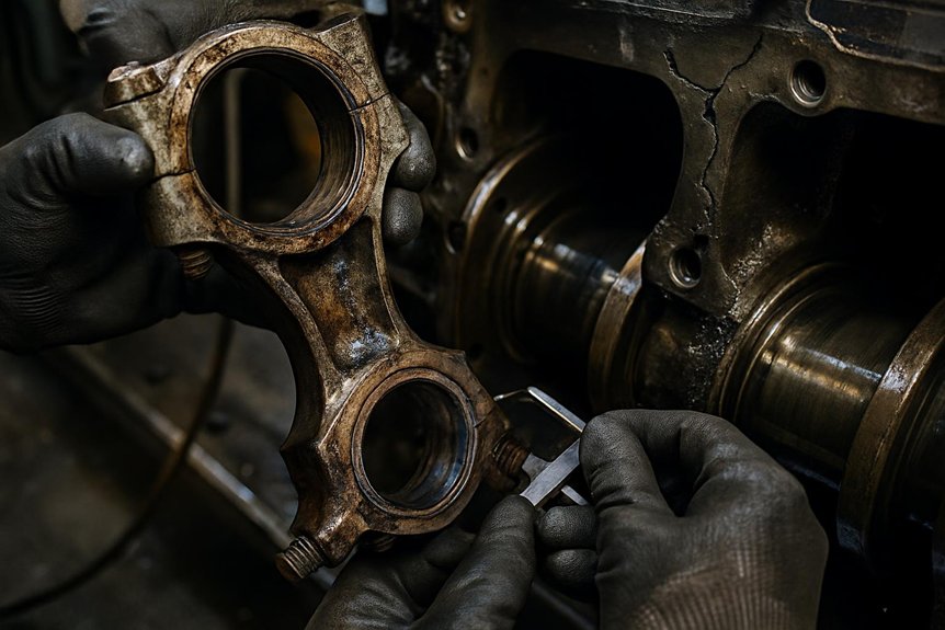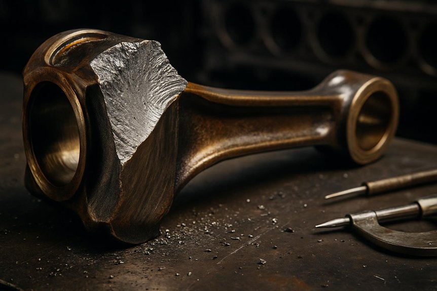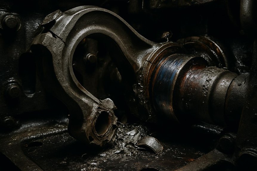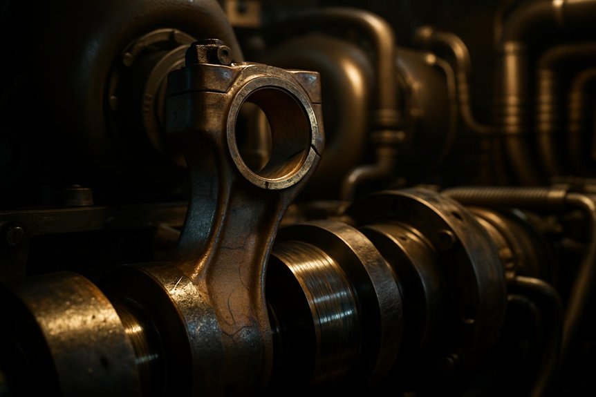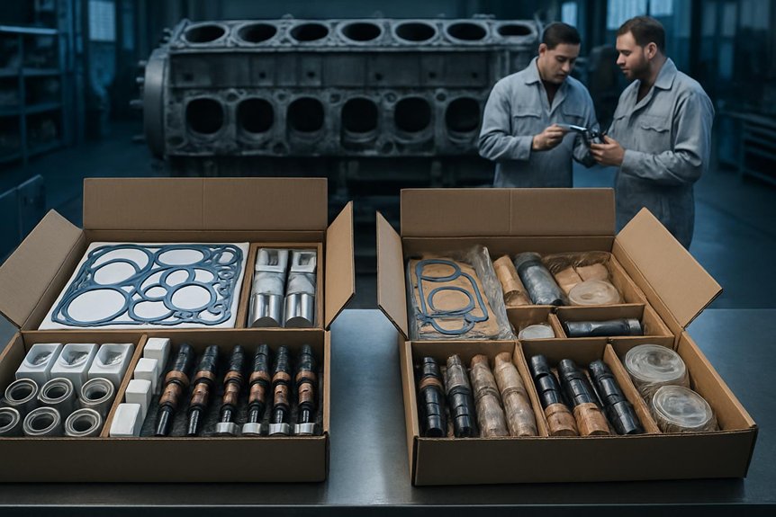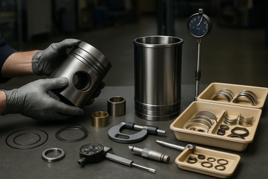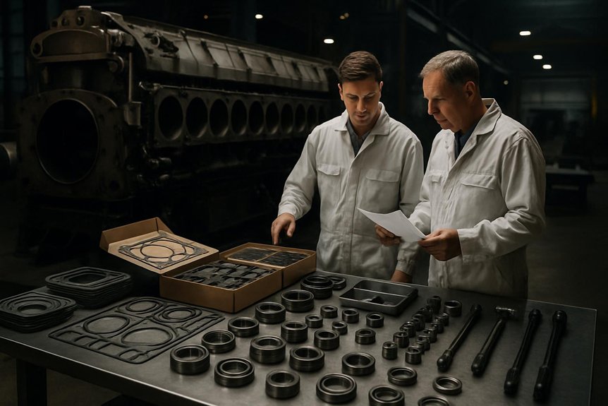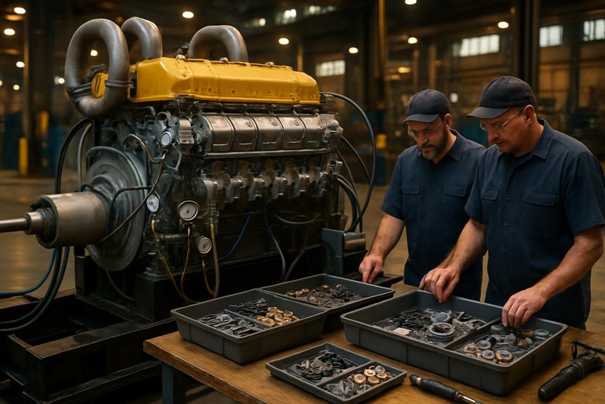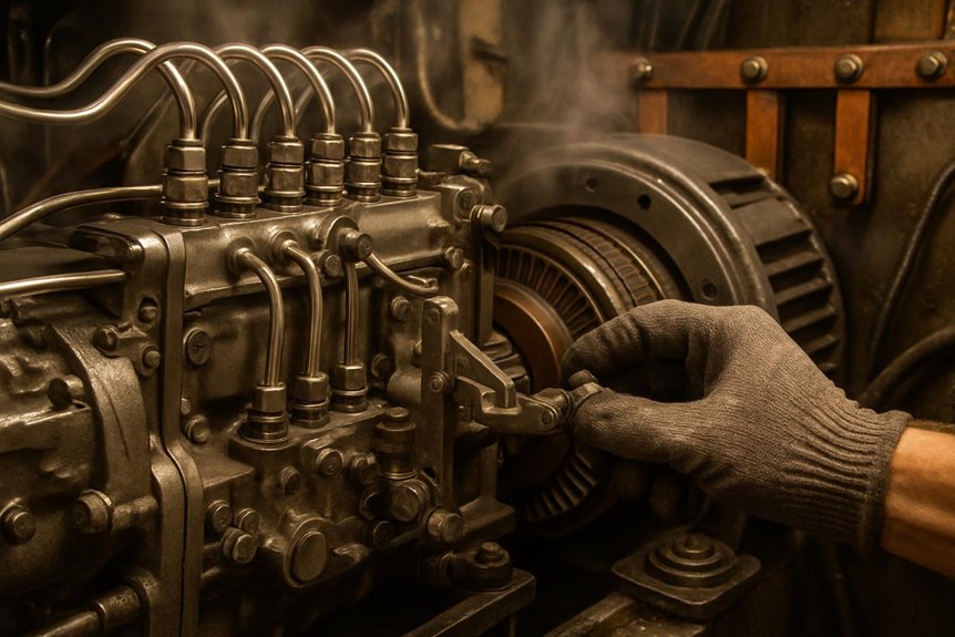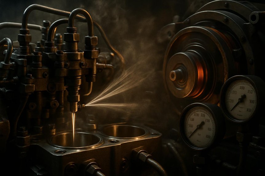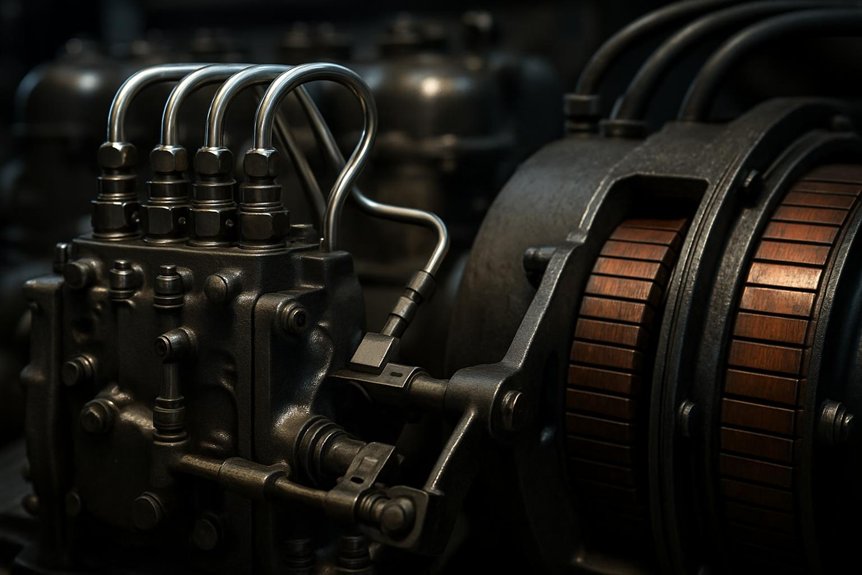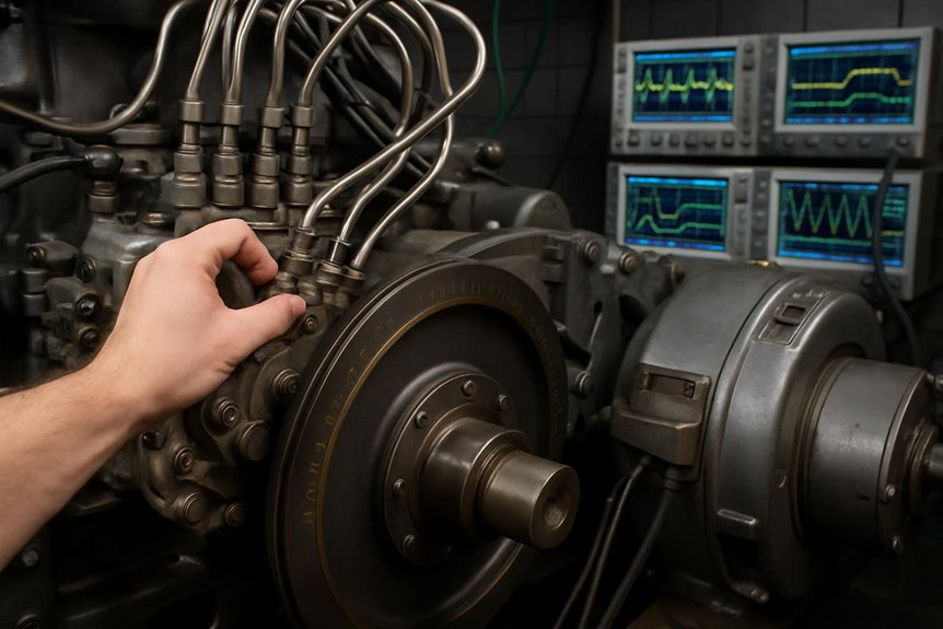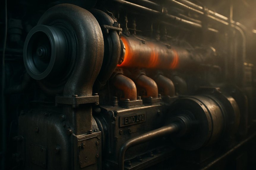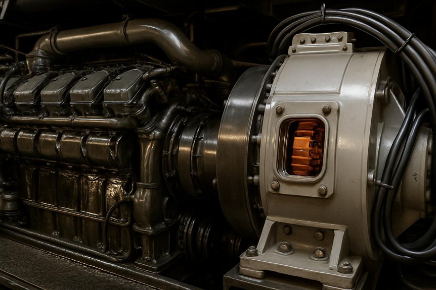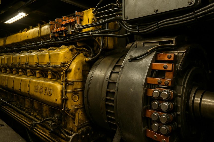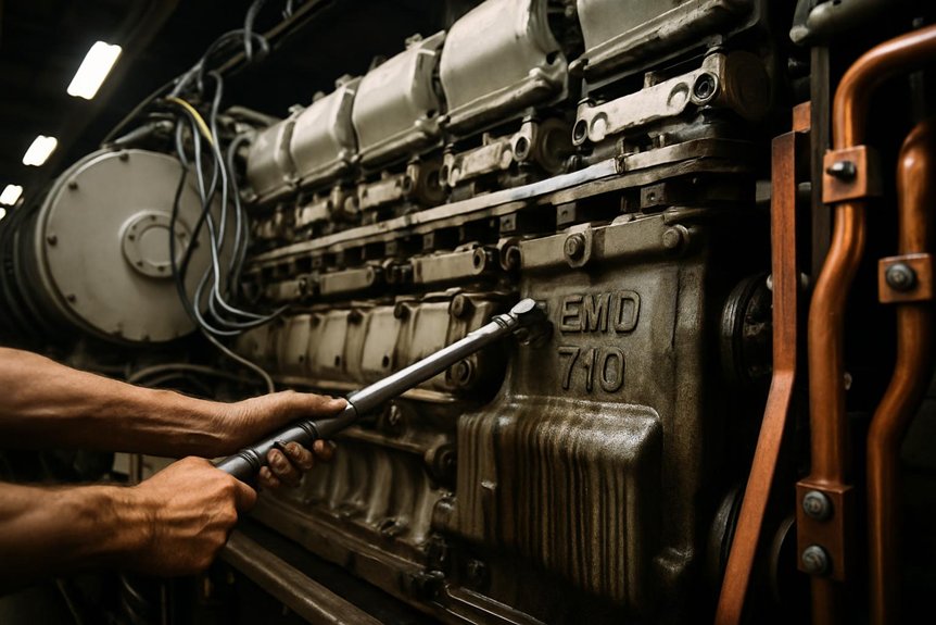
Temperature shifts oil film stability, material behavior, and axial load control. Heat changes material behavior, oil film stability, and axial load control. High temperature reduces wear resistance and reliability. Low temp can slow oil flow and increase friction. Both harm locomotive efficiency and engine efficiency. The result is lost tractive effort and higher maintenance risk. Addressing temp effects protects the EMD engine and extends lifespan under heavy railroad duty.
– Monitor oil temperature, pressure, and viscosity in real time. – Keep cooling systems clean, leak-free, and properly filled. – Verify blower, radiator fan, and shutter operation. – Use high-quality components with proven wear resistance. – Set throttle use to minimize heat soak after heavy freight pulls. – Inspect thrust washer axial faces during every scheduled service. – Align main bearings to reduce side loading. – Analyze oil for metal debris after high-temperature events. – Simulate duty cycles to validate temperature margins. – Calibrate temperature sensors to avoid false readings.
Focus Area
Action
Lubrication Monitoring
Monitor oil temperature, pressure, and viscosity in real time; analyze oil for metal debris after high-temperature events.
Cooling System
Keep systems clean, leak-free, and filled; verify blower, radiator fan, and shutter operation.
Component Durability
Use high-quality components with proven wear resistance; inspect thrust washer axial faces every service.
Operational Practices
Set throttle use to minimize heat soak after heavy freight pulls; simulate duty cycles to validate temperature margins.
Instrumentation
Calibrate temperature sensors to avoid false readings; align main bearings to reduce side loading.
As a brief guide, this article explains how temp influences an EMD thrust washer in a diesel locomotive prime mover. We detail materials, axial load paths, lubrication behavior, and controls that reduce wear. You will find practical steps to stabilize power output, protect the EMD diesel engine, and sustain performance and efficiency across US locomotives. We also share expert insights used by Mikura International, a top exporter of locomotive engine parts, to help you improve reliability.
Understanding EMD Locomotive Thrust Washers
In an EMD engine, the thrust washer manages axial loads on the crankshaft. It keeps the prime mover centered for stable torque transfer. Proper thrust control maintains valve timing, combustion stability, and tractive effort. Heat affects oil films between the bearing surfaces and the thrust washer, which can change wear rates. Managing temperature preserves locomotive efficiency and horsepower.
What is a Thrust Washer?
A thrust washer is a flat bearing element that resists axial motion of a rotating shaft. In an EMD diesel engine, it sits near main bearings to control endplay. It must survive hot oil, transient temp spikes, and start-stop thermal cycles. It works with the lube circuit to reduce wear during load changes. Kept cool and well lubricated, it preserves alignment, reduces friction, and supports consistent power.
Function of Thrust Washers in EMD Engines
Under changing throttle positions, axial loads push the crankshaft along its axis. The thrust washer maintains correct endplay to protect 645/710 geometry. This protects the 645 and 710 series geometry, keeps exhaust valve events accurate, and stabilizes piston and cylinder clearances. Stable endplay helps the generator and traction systems deliver steady tractive effort. Rising temperature thins oil films, increasing friction and reducing reliability, compromising locomotive performance and lifespan.
Common Materials Used in Thrust Washers
Typical thrust washer materials include steel-backed bronze, copper-lead, and aluminum-tin alloys. Some designs add overlays for wear resistance, conformability, and seizure resistance. Material choice must balance thermal conductivity, high-temp strength, and embeddability. EMD’s duty cycles demand alloys that handle hot oil near the exhaust passage and turbochargers zone. Proper pairing with crankshaft surfaces and oil chemistry preserves the bearing interface and supports consistent engine efficiency under load.
Impact of Temperature on Thrust Washer Performance
Temperature governs oil film behavior, material strength, and axial stability in an EMD engine. When temp rises, the thrust washer faces thinner lubrication and faster chemical oxidation of diesel engine oil. When temp falls, viscosity spikes and boundary friction grows. Both extremes threaten efficiency, horsepower, and tractive effort. To protect engine efficiency and reliability, keep systems cool, verify blower and radiator function, and monitor main bearings. Use high-quality components with strong wear resistance. Simulate duty cycles for freight operations. Balance throttle strategy to control heat soak. These actions reduce wear and extend thrust washer lifespan.
How Temperature Influences Material Properties
Elevated heat lowers yield strength and hardness, accelerating wear. Thermal expansion changes endplay and loads at the main bearings. Conductivity controls heat flow from the bearing to the crankcase, affecting oil film stability. At low temp, alloys may embrittle and lose conformability, risking scoring during cold starts. The EMD diesel environment near exhaust and turbochargers adds gradients. Matching alloy hardness to crankshaft surfaces helps reduce wear. Optimized overlays maintain seizure resistance and reliability across railway duty.
Effects of High Temperatures on Thrust Washers
High temperature thins oil and increases metal contact on the thrust washer. Oxidation forms varnish that restricts oil flow and raises friction. Softened overlays lose wear resistance, while copper-lead or aluminum-tin layers can smear under axial load. Heat from exhaust, turbochargers, and the generator region magnifies risks. Poor cooling cuts horsepower and power output as friction climbs. Blower performance and radiator airflow are vital to keep parts cool. Monitor oil pressure, endplay, and debris counts. Control throttle after heavy freight pulls to prevent heat soak. These steps protect reliability and extend lifespan.
Consequences of Low Temperatures on Performance
Low temperature thickens oil and delays full-film lubrication at startup. Boundary friction rises at the axial faces of the thrust washer, increasing wear until oil warms. Cold clearances shift as the cylinder block, piston assemblies, and main bearings contract, affecting endplay. The diesel lube circuit sees sluggish flow, reducing cooling near the thrust faces. Generator load changes can shock the interface before films form. Use preheaters where possible and short warm-up cycles. Avoid sudden throttle steps. Verify blower shutters and louvers. With controlled ramp-up, tractive effort stabilizes and locomotive reliability improves for us locomotives.
Key Factors to Consider for Optimal Performance
Control temperature, oil behavior, and axial loading for optimal thrust washer performance. Thermal gradients from exhaust and turbochargers can shift endplay and reduce wear resistance. Oil viscosity and flow must stay stable to maintain hydrodynamic films. Main bearings, piston assemblies, and the prime mover structure influence heat paths and torque stability. Operators should balance throttle, manage blower airflow, and keep the cooling loop clean. These steps protect horsepower, tractive effort, and locomotive efficiency in us locomotives during heavy freight duty and frequent load cycles.
Thermal Expansion and Compression
Uneven thermal expansion alters endplay and contact pressure. The 645 and 710 geometry can shift, changing axial loads and oil film thickness. If the crank web grows faster than the bearing carrier, contact pressure rises at the thrust faces. Compression during cooldown can pull films thin at idle. The result is higher friction and reduced engine efficiency. Map temperature rise near exhaust passages and turbochargers. Simulate hot restarts after steep grades. Maintain clearances with precise machining. Consistent thermal control preserves torque transfer and extends lifespan under railroad duty.
Lubrication and Its Role in Temperature Management
Correct viscosity is essential for hydrodynamic lift and heat removal. Lubrication manages heat by carrying energy from the thrust washer into the sump and cooler. As temp climbs, oil thins and boundary friction grows. As temp falls, flow lags and cooling weakens. Balance oil grade with expected ambient and duty cycles on the train. Verify generator load steps do not collapse films. Keep the lube cooler, blower shutters, and radiator path free of restrictions. Monitor varnish risk in diesel engine oil. Stable lubrication underpins reliability, horsepower, and power output in a diesel locomotive.
Monitoring and Maintenance Practices
Trending temperature, endplay, and debris prevents failures. Track oil temperature, pressure, and debris counts after long throttle pulls. Record endplay during every service. Inspect axial faces for scoring and overlay smear. Check blower performance, radiator airflow, and shutter response. Validate exhaust backpressure and coolant flow paths. Align main bearings and valve gear to minimize side loading. Use trending alerts to catch slow shifts in engine efficiency. When hotspots appear, simulate duty cycles to confirm margins. These disciplined steps protect locomotive efficiency, reduce wear, and sustain reliable tractive effort across railway operations.
Focus Area
Key Actions
Fluids and Debris
Track oil temperature, pressure, and debris counts after long throttle pulls; validate coolant flow paths; validate exhaust backpressure.
Mechanical Alignment
Record endplay during every service; align main bearings and valve gear to minimize side loading; inspect axial faces for scoring and overlay smear.
Thermal and Airflow Systems
Check blower performance, radiator airflow, and shutter response; use trending alerts to catch slow shifts in engine efficiency; simulate duty cycles when hotspots appear.
Outcome
Protect locomotive efficiency, reduce wear, and sustain reliable tractive effort across railway operations.
Practical Tips for EMD Locomotive Operators
Keep cooling systems clean and manage throttle to avoid heat soak. Practical actions help operators protect the thrust washer under variable temp and load. Keep cooling systems clean to maintain a cool oil supply. Sequence throttle changes to avoid heat soak. Verify turbochargers and exhaust components do not add excess heat. Watch generator loading steps near low speed. Align lubrication intervals with freight schedules. Use high-quality components for consistent wear resistance. When questions arise, Mikura International can advise on material upgrades and fitment. These measures stabilize torque delivery, preserve horsepower, and extend the prime mover’s lifespan in demanding EMD diesel service.
Regular Temperature Monitoring Techniques
Use calibrated sensors and trend data against load and throttle. Use calibrated sensors at oil galleries near the thrust washer and main bearings. Add infrared scans along the crankcase and exhaust side during heavy pulls. Log temperature against throttle position, generator load, and AC motor traction events. Compare warm-up curves after overnight cold soak on the railway. Set alarms for fast temperature rise that outpaces pressure. Trend coolant inlet and outlet deltas to detect fouling. Correlate debris in filters with spikes. These techniques improve reliability by catching early faults, protecting tractive effort and engine efficiency in US locomotives.
Action
Purpose/Metric
Use calibrated sensors at oil galleries near the thrust washer and main bearings
Accurate temperature and pressure readings at critical bearings
Add infrared scans along the crankcase and exhaust side during heavy pulls
Detect localized hot spots under high load
Log temperature vs. throttle position, generator load, and AC motor traction events
Correlate thermal behavior with operating conditions
Compare warm-up curves after overnight cold soak on the railway
Identify deviations in heat-up profiles
Set alarms for fast temperature rise that outpaces pressure
Early warning of lubrication or cooling issues
Trend coolant inlet/outlet deltas
Detect fouling in the cooling circuit
Correlate debris in filters with spikes
Link contamination events to operational anomalies
Best Practices for Thrust Washer Maintenance
Consistent endplay measurement and clean oil galleries are critical. Measure endplay with the same procedure each service to track axial drift. Inspect overlay condition and contact patterns on both thrust faces. Replace seals that admit dust, which accelerates wear under temp stress. Verify oil jets and galleries are clean and centered. Check valve train timing and piston-to-cylinder clearances that influence axial loading. Refresh oil before oxidation raises varnish and friction. After overheating events, sample oil and inspect for copper or tin. Follow torque specs on caps to maintain geometry. These practices reduce wear and sustain performance and efficiency in the EMD engine.
Upgrading Materials for Enhanced Performance
Choose alloys and overlays optimized for high-temperature duty. Consider steel-backed bronze with optimized overlays for high-temp reliability in a diesel locomotive prime mover. Enhanced aluminum-tin or copper-lead systems with solid lubricants can improve seizure resistance. Select alloys with better thermal conductivity to keep faces cool under freight loads. Match surface finish to the crank thrust collar for stable films. Validate upgrades with lab rigs and simulate duty cycles on the locomotive. Mikura International supplies high-quality components tailored to 645 and 710 applications. Proper material pairing preserves torque, power output, and locomotive efficiency while extending lifespan under railroad conditions.
Expert Insights on Thrust Washer Efficiency
Stable oil films, controlled temperature, and precise alignment drive efficiency. Thrust washer efficiency in an EMD engine hinges on stable oil films, controlled temp, and accurate axial alignment. Expert practice focuses on matching bearing materials to the prime mover’s thermal map, especially near exhaust and turbochargers. Engineers map heat flow from the cylinder block to main bearings to keep the thrust washer cool. They tune oil viscosity for freight duty, throttle transitions, and generator load steps. They validate endplay under simulated gradients. This protects tractive effort, torque, and locomotive efficiency in us locomotives while extending lifespan and reliability.
Industry Standards for EMD Components
Standards define endplay, surface finish, and hardness to stabilize films. Industry standards specify dimensional tolerances, surface finish, and hardness for thrust washer and main bearings in the EMD engine. They define endplay ranges for 645 and 710 families, oil gallery cleanliness, and overlay adhesion. Standards require consistent axial face flatness to stabilize films under diesel locomotive loads. Cool oil delivery and varnish control are emphasized. Inspection protocols mandate repeatable measurements and traceable gauges. Documentation links generator loading, blower airflow, and coolant temperatures to acceptance limits. These controls reduce wear, preserve horsepower, and sustain engine efficiency and power output on the railway.
Case Studies on Temperature Effects
Fixing cooling airflow and oil grade restored reliability in real fleets. A freight loco experienced rising debris counts after mountain grades. Data showed temp spikes near the thrust washer as blower shutters stuck. The oil thinned, and axial wear increased. Cleaning the shutters and adjusting throttle steps restored tractive effort and reliability. Another EMD diesel case saw cold starts on a northern railway. Viscosity was too high, delaying films at the axial faces. A revised oil grade and short warm-up stabilized torque. A third case used simulated duty cycles. It proved overlay upgrades improved wear resistance under exhaust-side heat, enhancing performance and efficiency.
Future Trends in Thrust Washer Technology
Advanced overlays, micro-textures, and embedded sensing will boost reliability. Future thrust washer designs will blend steel-backed bronze with advanced solid lubricants to reduce wear under variable temp. Micro-textured axial faces will hold oil and cool hotspots. Coatings with higher seizure resistance will protect during cold starts and sudden throttle changes. Embedded sensors may monitor temp, film status, and axial load in real time. Models will simulate railway gradients and ac motor traction events to predict risk. Optimized oil chemistries will resist oxidation near turbochargers. Together, these trends boost locomotive efficiency, horsepower stability, and lifespan in demanding diesel locomotive service.
Conclusion
Effective temperature control stabilizes oil films, torque transfer, and engine efficiency. Effective temperature control protects the thrust washer, the generator coupling, and the prime mover’s axial balance. It keeps oil films stable across main bearings and axial faces. This secures torque transfer, tractive effort, and engine efficiency in an EMD diesel. Operators should monitor coolant, blower performance, and exhaust-side hotspots. They should select high-quality components and match oil to duty. Validated maintenance and simulated freight profiles mitigate risk. The result is consistent power output, reliable combustion, and longer lifespan for us locomotives across harsh railway environments.
Recap of Temperature Impact on Performance
High temp thins oil; low temp raises viscosity-both shift axial loads and cut efficiency. High temp thins oil, weakens overlays, and raises friction at the thrust washer. Low temp increases viscosity and delays hydrodynamic lift. Both shift axial loads and reduce locomotive efficiency. Exhaust heat and turbochargers intensify gradients. Poor cooling harms horsepower and torque stability. Proper oil grade, clean radiators, and working shutters keep components cool. Endplay checks and debris trending reduce wear. When operators control throttle steps and validate generator load transitions, tractive effort stays steady. These actions preserve performance and efficiency in the EMD engine across 645 and 710 platforms.
Final Thoughts on EMD Thrust Washers
Control temperature, confirm axial geometry, and maintain clean lubrication. Precision in materials, oil selection, and alignment defines thrust washer success in a diesel locomotive. Control temp, confirm axial geometry, and maintain clean lubrication. Use overlays with proven wear resistance and conformability. Map thermal paths near the exhaust valve region to prevent local hotspots. Simulate steep grades and hot restarts to validate margins. When maintained well, the thrust washer protects the prime mover, generator, and traction motor systems. It safeguards locomotive reliability, power output, and torque delivery under heavy freight duty on the railroad and the wider railway network.
How Mikura International Supports Engine Parts Excellence
Mikura International supplies optimized thrust washer solutions and guidance. Mikura International provides high-quality components for EMD engines, including thrust washer solutions tailored to 645 and 710 duty. We advise on alloys, overlays, and surface finishes to keep axial faces cool and reduce wear. Our experts help match oil chemistry and endplay targets to freight cycles. We simulate gradients and load steps to confirm performance. We support inspection protocols, debris trending, and geometry control. With our guidance, operators improve engine efficiency, horsepower stability, and tractive effort. That strengthens reliability and extends lifespan across us locomotives and global railway fleets.
Critical Protection: The Turbo Soak Back Pump 40182032 provides essential auxiliary lubrication for EMD locomotive engines, circulating filtered oil for 30, 35 minutes after shutdown to prevent heat-induced damage.
Fuel Efficiency & Reliability: By preventing “oil coking” (the buildup of hard carbon deposits), the pump maintains peak turbocharger performance, which directly reduces fuel consumption and prevents costly unplanned downtime.
Component Longevity: The system ensures bearings are pre-lubricated before startup and cooled post-shutdown, effectively preventing shaft seizure, bearing degradation, and thermal breakdown of the oil.
Maintenance Best Practices: For optimal results, operators should follow strict installation procedures, monitor oil pressure regularly, and adhere to filter replacement schedules to protect the turbocharger’s rotating assembly.
Turbo Soak Back Pump 40182032 and Fuel Efficiency
Locomotive maintenance managers often face significant challenges. Premature turbocharger failure is a major concern. This leads to costly repairs and unexpected downtime. These issues severely impact operational efficiency and budget. Mikura International understands these pain points.
Implement a strict maintenance schedule.
Monitor turbocharger performance regularly.
Ensure proper lubrication systems are active.
Address any warning signs immediately.
Use high-quality replacement parts.
Train staff on best practices.
Function and Role of Turbo Soak Back Pump 40182032
The Turbo Soak Back Pump 40182032 is an auxiliary lubrication system. It is vital for locomotive maintenance. This pump circulates filtered oil post-engine shutdown. This process significantly reduces oil coking. Reduced coking directly impacts fuel efficiency. It maintains optimal turbocharger performance.
This critical component supports EMD locomotive engines. It ensures the turbine wheel and rotating assembly remain lubricated. The pump prevents thermal breakdown. It extends the life of bearing assemblies. This proactive measure is key for engine reliability.
Impact of Oil Coking on Locomotive Fuel Efficiency
Oil coking is a severe problem. It causes bearing degradation within the turbocharger. This degradation decreases turbocharger efficiency. Consequently, increased fuel consumption occurs. It also leads to unplanned downtime and costly repairs.
Preventing oil coking is crucial. The Turbo Soak Back Pump 40182032 achieves this. It improves engine reliability and operational efficiency. Mikura International provides solutions to combat coking. This ensures sustained fuel efficiency for diesel locomotives.
Installation and Inspection Procedures for the Soak Back Pump
Proper installation of the Turbo Soak Back Pump 40182032 is essential. Begin with a preliminary inspection. Check the Soak Back Filter and all piping. Verify electric motor functionality. Ensure correct mounting of the pump unit. Route oil lines properly.
Specific torque values are critical. Use recommended line diameters. These steps ensure optimal operation. Regular inspection of the check valve testing is also vital. This prevents future issues with bearing lubrication. Mikura International provides expert guidance.
Operational Control and Automatic System Integration
The Turbo Soak Back Pump 40182032 operates automatically. The locomotive control computer manages it. It activates during engine shutdown cycles. The pump runs for 30-35 minutes. This prevents thermal buildup in the turbocharger. Maintaining turbocharger efficiency is paramount.
This automated process protects the rotating assembly. It ensures proper bearing lubrication. The system integrates seamlessly with the main lubrication system. This prevents oil oxidation and hydrocarbon cracking. It is a smart solution for locomotive maintenance.
Pre-startup Lubrication and Post-shutdown Cooling Cycles
Activating the Turbo Soak Back Pump 40182032 before startup is beneficial. This ensures bearings are pre-lubricated. Pre-lubrication reduces wear significantly. Post-shutdown circulation is equally important. It prevents heat-induced oil cracking and coking.
This continuous oil circulation preserves component longevity. It protects the main oil gallery. The process ensures the bearing clearance remains optimal. It prevents shaft seizure. This extends turbocharger service intervals.
Effects of Oil Coking on Bearing and Turbocharger Life
Oil coking causes severe damage. It leads to carbon deposits on bearing assemblies. This results in scoring and potential shaft seizure. These issues drastically shorten turbocharger life. They increase unplanned downtime.
Maintaining continuous oil circulation minimizes these damages. The Turbo Soak Back Pump 40182032 achieves this. It reduces thermal and mechanical wear. This extends turbocharger service life. It keeps the rotating assembly in prime condition.
Benefits of Continuous Oil Circulation Post-Shutdown
Continuous oil circulation post-shutdown offers significant benefits. It reduces thermal stress on turbo bearings. This prevents carbon buildup. It sustains optimal fuel efficiency over time. Studies indicate improved engine reliability.
The Turbo Soak Back Pump 40182032 ensures this circulation. It keeps oil temperatures below the thermal stability threshold. This prevents oil coking. It protects vital bearing assemblies. Mikura International supports enhanced component longevity.
Function and Role of Turbo Soak Back Pump 40182032
The Turbo Soak Back Pump 40182032 is a vital component. It operates as an auxiliary lubrication system. This system functions after engine shutdown. It circulates filtered oil to the turbocharger bearings. This action significantly reduces oil coking. Oil coking is a primary cause of turbocharger degradation. Preventing coking maintains optimal turbocharger performance. This directly enhances EMD locomotive engines fuel efficiency. The pump ensures continuous lubrication during critical cooling phases. This extends the service life of the turbocharger. It also contributes to overall engine reliability in EMD locomotive engines.
Impact of Oil Coking on Locomotive Fuel Efficiency
Oil coking directly harms locomotive fuel efficiency. It causes deposits on bearing assemblies. These deposits lead to increased friction and wear. This degrades turbocharger efficiency over time. A less efficient turbocharger means the engine works harder. This results in higher fuel consumption. It also causes increased emissions. Oil coking shortens the lifespan of critical components. This necessitates more frequent maintenance. It also leads to expensive repairs and unplanned downtime. The Turbo Soak Back Pump 40182032 actively prevents this. It maintains cleaner bearings. This ensures the turbocharger operates at peak efficiency. This directly translates to improved fuel economy.
Installation and Inspection Procedures
Proper installation of the Turbo Soak Back Pump 40182032 is critical. It ensures long-term locomotive maintenance success. Before installation, perform preliminary inspections. Check the soak back filter and piping for damage. Verify the integrity of the oil gallery network. Ensure all connections are clean and secure. Mount the pump according to manufacturer specifications. Route oil lines carefully to avoid kinks. Use correct torque values for all fasteners. Recommended line diameters must be used. These steps ensure optimal operation. Mikura International provides detailed guides for installation. Always follow these procedures for best results. This prevents costly unplanned downtime.
Operational Control and Automatic System Integration
The Turbo Soak Back Pump 40182032 integrates seamlessly. It connects with the locomotive’s control system. This ensures robust Turbocharger management. It activates automatically during engine shutdown cycles. This activation lasts for approximately 30-35 minutes. This timing is critical for preventing thermal buildup. The auxiliary cooling system circulates oil. This process cools the hot turbocharger bearing assemblies. This prevents thermal breakdown of the oil. This automatic operation requires no manual intervention. It ensures consistent protection. The locomotive control computer manages this system. Proper integration is key to maintaining turbocharger efficiency and Engine reliability.
Automated Auxiliary Cooling System Operation
The Turbo Soak Back Pump 40182032 functions as a vital auxiliary lubrication system. It activates automatically. This occurs immediately after the Diesel Prime Mover shuts down. The system circulates pressurized oil. This oil flows through the turbine wheel and bearing assemblies. This continuous flow prevents oil coking. Oil coking forms damaging carbon deposits. These deposits occur when residual heat bakes stagnant oil. Preventing this coking is crucial. It directly impacts locomotive fuel efficiency. Maintaining clean bearing clearances is essential. This extends the service intervals for EMD locomotive engines.
Preventing Thermal Breakdown and Carbon Deposits
Engine shutdown cycles generate significant residual heat. This heat concentrates in the turbocharger. Without the Turbo Soak Back Pump 40182032, oil stagnates. It reaches its thermal stability threshold. This causes rapid oil oxidation and hydrocarbon cracking. The result is harmful carbon deposits and thermal breakdown. These deposits adhere to bearing surfaces. They lead to increased friction and wear. This compromises the rotating assembly. Mikura International emphasizes preventing these issues. Continuous oil circulation post-shutdown is vital. It maintains bearing lubrication and cools components. This significantly reduces unplanned downtime.
Role of the Locomotive Control Computer
The locomotive control computer is central. It manages the Turbo Soak Back Pump 40182032. This computer monitors engine parameters. It initiates the soak back cycle precisely. This ensures the 30-35 minute run time. This duration is engineered for optimal cooling. It prevents heat-induced oil cracking. The system also performs check valve testing. This ensures proper oil flow. Effective integration maintains the main lubrication system integrity. It extends component longevity. This smart control prevents shaft seizure. It protects the critical bearing assemblies.
Benefits of Continuous Oil Circulation Post-Shutdown
Maintaining oil flow after shutdown offers significant benefits. It reduces thermal stress on turbo bearings. This prevents carbon buildup. This sustains optimal locomotive fuel efficiency over time. Studies indicate this practice extends turbocharger service life. It minimizes damages from thermal and mechanical wear. The Turbo Soak Back Pump 40182032 ensures this circulation. It draws oil from the oil gallery network. It filters it through the Soak Back Filter. This delivers clean oil to the bearing assemblies. This pre-lubrication also aids startup. It reduces initial wear. This protects your investment in EMD locomotive engines.
Pre-startup Lubrication and Post-shutdown Cooling Cycles
The Turbo Soak Back Pump 40182032 performs two vital functions. It ensures engine reliability. This pump prevents unplanned downtime.
Before engine startup, the Turbo Soak Back Pump 40182032 provides critical pre-lubrication to the bearing assemblies. This reduces wear during initial engine rotation. It prepares the rotating assembly for operation. This action prolongs component longevity for the diesel prime mover.
Post-shutdown, the pump maintains essential oil circulation. This prevents heat-induced oil cracking. It stops oil coking. This continuous flow after shutdown minimizes thermal stress on the turbine wheel and bearing assemblies. It is a key aspect of Turbocharger Lubrication.
The auxiliary lubrication system ensures the main lubrication system remains primed. This prevents dry starts. It protects critical components. This dual action significantly extends the service intervals of EMD locomotive engines.
This process is crucial for preventing Carbon deposits. It maintains Bearing clearance. It ensures the thermal stability threshold of the oil is not breached. Mikura International emphasizes these benefits.
Studies indicate that continuous oil flow after shutdown significantly reduces thermal stress on turbo bearings. This prevents carbon buildup. It sustains optimal fuel efficiency over time. This extends the turbocharger’s service life.
Effects of Oil Coking on Bearing and Turbocharger Life
Oil coking severely impacts bearing and turbocharger life. It forms hard carbon deposits on bearing surfaces. These deposits cause scoring and increased friction. This can lead to premature wear. In severe cases, it causes shaft seizure. This necessitates costly turbocharger replacement. The Turbo Soak Back Pump 40182032 mitigates these risks. It ensures continuous oil circulation. This prevents carbon buildup. This action reduces thermal and mechanical wear. It extends the turbocharger’s service life significantly. This protects your investment and reduces maintenance costs.
Impact of Oil Coking on Locomotive Fuel Efficiency
Oil coking directly impacts locomotive fuel efficiency. Bearing degradation from coking decreases turbocharger efficiency. This leads to increased fuel consumption. It also causes costly unplanned downtime. Preventing oil coking with the Turbo Soak Back Pump 40182032 improves engine reliability. It sustains optimal operational efficiency. This pump reduces thermal stress on turbo bearings. It prevents carbon deposits. This helps maintain consistent fuel efficiency over time.
Benefits of Continuous Oil Circulation Post-Shutdown
Maintaining oil flow after engine shutdown is crucial. The Turbo Soak Back Pump 40182032 provides this continuous circulation. It reduces thermal stress on turbo bearings. This prevents carbon buildup. It also minimizes oil oxidation and hydrocarbon cracking. This action sustains optimal fuel efficiency. It extends the service intervals for EMD locomotive engines. This proactive measure prevents costly repairs. It ensures longer component longevity for the rotating assembly.
Understanding Thermal Breakdown and Carbon Deposits
Thermal breakdown of oil is a primary cause of carbon deposits. High temperatures in the turbine wheel area lead to oil coking. When the main lubrication system shuts down, residual heat remains. This heat exceeds the oil’s thermal stability threshold. The Turbo Soak Back Pump 40182032 circulates cooler oil. This prevents localized overheating. It flushes away potential carbon-forming particles. This protects the bearing assemblies from damage. Mikura International emphasizes preventing thermal breakdown for optimal performance.
Benefits of Continuous Oil Circulation Post-Shutdown
Continuous oil circulation after engine shutdown offers critical advantages. It significantly reduces thermal stress on turbo bearings. This action prevents the formation of harmful carbon deposits. These deposits are a primary cause of premature wear. The Turbo Soak Back Pump 40182032 is essential here. It ensures critical bearing lubrication.
Preventing Thermal Breakdown and Carbon Deposits
Continuous circulation helps dissipate residual heat from the turbine wheel. This protects the oil from thermal breakdown. It maintains oil quality within the main lubrication system. This sustained protection helps the turbocharger perform optimally. This directly contributes to consistent fuel efficiency. Mikura International emphasizes this critical advantage.
Studies show this practice extends turbocharger life. It minimizes the need for unscheduled maintenance. This reduces unplanned downtime for diesel locomotive engines. The auxiliary lubrication system prevents hydrocarbon cracking. This protects the rotating assembly.
Impact of Oil Coking on Locomotive Fuel Efficiency
Oil coking severely impacts locomotive fuel efficiency. It leads to bearing degradation within the turbocharger. This decreases overall turbocharger efficiency. In turn, this causes increased fuel consumption. Preventing coking with the Turbo Soak Back Pump 40182032 improves reliability. It enhances operational efficiency. The pump maintains the thermal stability threshold of the oil. This prevents carbon deposits from forming. These deposits restrict oil flow within the oil gallery network.
Effects of Oil Coking on Bearing and Turbocharger Life
Oil coking causes hard carbon deposits on bearing surfaces. These deposits lead to scoring and increased friction. This accelerates premature wear of bearing assemblies. In severe cases, it can cause shaft seizure. This necessitates costly turbocharger replacement. The Turbo Soak Back Pump 40182032 mitigates these risks. It ensures continuous oil circulation. This prevents carbon buildup. This action reduces thermal and mechanical wear. It extends the service intervals for EMD locomotive engines.
Expert Insight
“Turbo soak-back pumps are essential for maintaining the thermal stability threshold of the oil immediately upon engine shutdown; by ensuring continuous circulation, they prevent oil from being burnt and baked to the shaft, effectively avoiding the hard carbon deposits and coking that lead to expensive bearing degradation and turbocharger failure.” , Heavy-Duty Equipment Engineering Specialist
Understanding Turbocharger Lubrication
Turbochargers operate at extreme temperatures. Their bearings require constant, clean oil. The main lubrication system provides pressurized oil. This occurs during engine operation. Oil flows through an intricate oil gallery network. After engine shutdown, the main lube pump stops. Residual heat can then cause oil to bake onto hot surfaces. This leads to oil coking. This is where the Turbo Soak Back Pump 40182032 becomes indispensable. It ensures vital lubrication continues. This protects against thermal breakdown. It safeguards the entire rotating assembly. Proper bearing lubrication is key to engine reliability.
Function and Role of Turbo Soak Back Pump 40182032
The Turbo Soak Back Pump 40182032 functions as an auxiliary lubrication system. It circulates filtered oil post-shutdown. This significantly reduces oil coking. It maintains peak turbocharger performance. This directly impacts locomotive fuel efficiency. The pump ensures continuous flow. This prevents heat-induced damage to critical bearing assemblies. Mikura International provides reliable components for this system.
Impact of Oil Coking on Locomotive Fuel Efficiency
Oil coking causes rapid bearing degradation. This decreases turbocharger efficiency. It leads to increased fuel consumption. It also results in costly unplanned downtime. Preventing coking with the Turbo Soak Back Pump 40182032 improves reliability. It enhances operational efficiency. This protects your investment in diesel locomotive engines. It extends component longevity for critical parts like the turbine wheel.
Preventing Thermal Breakdown and Carbon Deposits
Continuous oil circulation after engine shutdown offers critical advantages. It significantly reduces thermal stress on turbo bearings. This action prevents the formation of harmful carbon deposits. These deposits are a primary cause of premature wear. The Turbo Soak Back Pump 40182032 is essential here. It ensures critical bearing lubrication. This safeguards the entire rotating assembly. It maintains the thermal stability threshold of the oil. This prevents hydrocarbon cracking and oil oxidation.
Common Pain Points and Solutions
Spare parts sourcing managers face significant challenges. Finding reliable components is often difficult. Ensuring timely delivery presents another hurdle. Dealing with unexpected component failures is a common pain point. The Turbo Soak Back Pump 40182032 directly addresses these issues. It significantly reduces turbocharger failures. This lowers costly unplanned downtime. Mikura International guarantees on-time delivery of quality parts. Our focus is on solving your operational problems. We provide solutions that enhance engine reliability. This helps manage service intervals effectively. We ensure your EMD locomotive engines run efficiently.
Feature
Without Soak Back Pump
With Turbo Soak Back Pump 40182032
Oil Coking Risk
High
Low
Turbocharger Lifespan
Reduced
Extended
Fuel Efficiency
Compromised
Maintained / Improved
Bearing Wear
Significant
Minimal
Unplanned Downtime
Frequent
Reduced
Maintenance Costs
Higher
Lower
Engine Reliability
Lower
Higher
Function and Role of Turbo Soak Back Pump 40182032
The Turbo Soak Back Pump 40182032 is an auxiliary lubrication system. It operates after engine shutdown. This pump circulates filtered oil. Its primary role is to reduce oil coking. This directly impacts locomotive fuel efficiency. Maintaining turbocharger performance is key. The pump prevents residual heat from damaging bearing assemblies.
Impact of Oil Coking on Locomotive Fuel Efficiency
Oil coking leads to severe bearing degradation. This decreases turbocharger efficiency. Degraded turbochargers cause increased fuel consumption. This results in costly unplanned downtime. Preventing coking with the soak back pump improves reliability. It enhances overall operational efficiency. This protects your diesel locomotive investment.
Installation and Inspection Procedures
Proper installation procedures are critical. Begin with a preliminary inspection. Check filters, piping, and the electric motor functionality. Ensure correct mounting of the Turbo Soak Back Pump 40182032. Route oil lines precisely. Adhere to specific torque values. Use recommended line diameters. This ensures optimal operation and component longevity.
Operational Control and Automatic System Integration
The Turbo Soak Back Pump 40182032 integrates automatically. The locomotive control computer manages its activation. It engages during engine shutdown cycles. The pump typically runs for 30-35 minutes. This prevents thermal buildup. This is essential for maintaining turbocharger efficiency. It safeguards the rotating assembly.
Pre-startup Lubrication and Post-shutdown Cooling Cycles
Activating the Turbo Soak Back Pump 40182032 before startup is beneficial. It ensures bearing lubrication is established. This reduces initial wear on bearing assemblies. Post-shutdown circulation is equally vital. It prevents heat-induced oil oxidation. This stops hydrocarbon cracking and carbon deposits. This maintains the thermal stability threshold.
Effects of Oil Coking on Bearing and Turbocharger Life
Oil coking causes damaging deposits. It leads to scoring and potential shaft seizure. Maintaining continuous oil circulation minimizes these damages. This is achieved by the Turbo Soak Back Pump 40182032. It extends turbocharger service life. It reduces thermal and mechanical wear. This preserves bearing clearance.
Benefits of Continuous Oil Circulation Post-Shutdown
Maintaining oil flow after shutdown reduces thermal stress. This protects turbo bearings. It prevents carbon buildup. Studies show this sustains optimal fuel efficiency over time. The auxiliary cooling system supports this. This ensures the main lubrication system remains effective. The pump draws from the main oil gallery.
Maintaining Optimal Thermal Stability Threshold
The thermal stability threshold of lubricating oil is crucial. High temperatures after engine shutdown can exceed this threshold. This causes oil to degrade. It forms carbon deposits. These deposits lead to hydrocarbon cracking. The Turbo Soak Back Pump 40182032 prevents this. It circulates cooler oil. This keeps bearing assemblies temperatures below critical levels. It protects the oil’s integrity. It ensures effective lubrication. Maintaining this threshold is vital. It preserves component longevity. It sustains peak turbocharger management. This supports locomotive fuel efficiency.
Function and Role of Turbo Soak Back Pump 40182032
The Turbo Soak Back Pump 40182032 acts as an auxiliary lubrication system. It significantly reduces oil coking. It circulates filtered oil post-shutdown. This maintains turbocharger performance. Ultimately, this directly impacts locomotive fuel efficiency. Mikura International supplies these vital pumps. They enhance the reliability of your diesel locomotive.
Impact of Oil Coking on Locomotive Fuel Efficiency
Oil coking severely impacts locomotive fuel efficiency. It causes bearing degradation. This decreases turbocharger efficiency. Increased fuel consumption results. It leads to costly unplanned downtime. Preventing coking with the Turbo Soak Back Pump 40182032 is key. It improves engine reliability and operational efficiency. This protects your EMD locomotive engines.
Installation and Inspection Procedures
Proper installation procedures are critical. First, inspect filters and piping. Check electric motor functionality. Ensure correct mounting. Route lines precisely. Mikura International provides detailed guidelines. Recommended specific torque values exist. Use correct line diameters. This ensures optimal operation of the cooling system.
Operational Control and Automatic System Integration
The Turbo Soak Back Pump 40182032 operates automatically. The locomotive control computer controls it. It activates during engine shutdown cycles. It runs for 30-35 minutes. This prevents thermal buildup. This is essential for maintaining turbocharger lubrication. It ensures sustained engine reliability.
Pre-startup Lubrication and Post-shutdown Cooling Cycles
Activating the Turbo Soak Back Pump 40182032 before startup ensures pre-lubrication. This reduces wear on bearing assemblies. Post-shutdown circulation prevents heat-induced oil cracking. It stops carbon deposits formation. This extends the life of the turbine wheel and rotating assembly.
Effects of Oil Coking on Bearing and Turbocharger Life
Oil coking causes deposits and scoring. It can lead to shaft seizure. Maintaining continuous oil circulation minimizes these damages. This extends turbocharger service life. It reduces thermal and mechanical wear. This protects your investment in locomotive maintenance.
Benefits of Continuous Oil Circulation Post-Shutdown
Maintaining oil flow after shutdown reduces thermal stress. This protects turbo bearings. It prevents carbon buildup. This sustains optimal locomotive fuel efficiency over time. The Turbo Soak Back Pump 40182032 ensures these benefits. It uses the main lubrication system effectively. It provides pressurized oil through the oil gallery network.
Expert Insight
“The Turbo Lube Oil Soak Back Pump (40182032) is critical for locomotive longevity; by ensuring pre-lubrication and post-shutdown circulation, it prevents heat-induced oil cracking and carbon deposits that otherwise lead to shaft seizure and premature turbocharger failure.” , Locomotive Engineering Specialist
Monitoring and Pressure Testing the Soak Back System
Regular monitoring of the Turbo Soak Back Pump 40182032 system is essential. Check oil pressure and flow rates. Ensure the pump activates correctly after engine shutdown cycles. Perform pressure testing periodically. This verifies system integrity. It identifies potential leaks or blockages. Inspect the check valve testing. This ensures proper oil flow direction. Regular checks prevent system malfunctions. They guarantee continuous protection for the turbocharger. Mikura International recommends a strict monitoring schedule. This proactive approach prevents costly failures. It supports overall locomotive maintenance efforts.
Operational Control and Automatic System Integration
The Turbo Soak Back Pump 40182032 is controlled automatically. The locomotive control computer manages its activation. It engages during engine shutdown cycles. The pump operates for 30-35 minutes. This prevents thermal buildup. This action maintains turbocharger efficiency. Automated operation ensures consistent performance. It reduces manual intervention needs. This system integration is vital for engine reliability. It prevents issues like oil coking.
Pre-startup Lubrication and Post-shutdown Cooling Cycles
Activating the Turbo Soak Back Pump 40182032 before startup is critical. It ensures bearing assemblies are pre-lubricated. This significantly reduces initial wear. Post-shutdown circulation prevents heat-induced oil cracking. It stops carbon deposits from forming. This dual-phase operation extends component longevity. It protects the rotating assembly. This system prevents thermal breakdown. It is an essential part of effective turbocharger management.
Benefits of Continuous Oil Circulation Post-Shutdown
Maintaining oil flow after shutdown is crucial. Studies show it reduces thermal stress on turbocharger bearings. This prevents carbon buildup. It sustains optimal fuel efficiency over time. Continuous circulation also minimizes oil oxidation. It maintains the thermal stability threshold. This process protects the turbine wheel. It ensures the diesel prime mover operates efficiently. This proactive cooling is a cornerstone of locomotive maintenance.
System Maintenance: Filter Replacement and Cleaning
Effective system maintenance includes regular filter replacement. The soak back filter traps contaminants. A clogged filter reduces oil flow. This compromises lubrication. Replace filters according to service intervals. Clean the system piping as needed. Inspect for any debris or sludge buildup. Proper cleaning ensures optimal oil quality. This prevents abrasive wear on bearing assemblies. This routine maintenance is vital. It supports the component longevity of the Turbo Soak Back Pump 40182032. It also protects the turbocharger’s rotating assembly.
Impact of Oil Coking on Locomotive Fuel Efficiency
Oil coking significantly impacts locomotive fuel efficiency. It leads to bearing degradation within the turbocharger. This decreases overall turbocharger efficiency. Increased fuel consumption is a direct result. Costly unplanned downtime also occurs. Preventing oil coking with the Turbo Soak Back Pump 40182032 improves engine reliability. It also enhances operational efficiency for diesel locomotive engines. Mikura International emphasizes preventative measures.
Effects of Oil Coking on Bearing and Turbocharger Life
Oil coking causes detrimental deposits. It leads to scoring and potential shaft seizure. Maintaining continuous oil circulation minimizes these damages. This extends turbocharger service life. It reduces thermal and mechanical wear. The Turbo Soak Back Pump 40182032 is crucial here. It prevents thermal breakdown and carbon deposits. This protects the turbine wheel and its bearings. Mikura International parts ensure robust performance.
Benefits of Continuous Oil Circulation Post-Shutdown
Continuous oil flow after engine shutdown is vital. It reduces thermal stress on turbo bearings. This prevents carbon buildup. Optimal fuel efficiency is sustained over time. The Turbo Soak Back Pump 40182032 facilitates this. It provides auxiliary lubrication during engine shutdown cycles. This process maintains the thermal stability threshold of the oil. It prevents oil oxidation and hydrocarbon cracking. This ensures cleaner bearing lubrication.
Materials and Design Features of Pump and Piping
The Turbo Soak Back Pump 40182032 is built for durability. It uses robust materials. These materials withstand harsh locomotive environments. The piping system is designed for high-pressure oil flow. It resists corrosion and vibration. The pump motor is engineered for continuous operation. These design features ensure reliable performance. They contribute to the component’s extended lifespan. Mikura International supplies parts meeting these high standards. Quality materials prevent premature failure. They ensure consistent auxiliary lubrication.
Control System Logic and Timing of Pump Activation
The locomotive control computer governs pump activation. Its logic dictates precise timing. The Turbo Soak Back Pump 40182032 engages immediately after engine shutdown. This is part of the auxiliary cooling system. It runs for a programmed duration. This duration is typically 30-35 minutes. This ensures adequate cooling. It prevents oil coking. The control system monitors engine parameters. It ensures the pump operates only when needed. This intelligent control maximizes efficiency. It minimizes energy consumption. Proper calibration of this logic is crucial. It ensures optimal protection for the turbocharger. This system is vital for Locomotive Maintenance.
Operational Control and Automatic System Integration
The Turbo Soak Back Pump 40182032 is controlled automatically. The locomotive’s computer manages this. It activates during engine shutdown cycles. This prevents thermal buildup. This is essential for maintaining turbocharger efficiency. The pump circulates oil for 30-35 minutes. This post-shutdown cooling prevents oil oxidation. It stops hydrocarbon cracking. This protects the turbine wheel and rotating assembly. It ensures component longevity. Mikura International emphasizes this critical integration.
Pre-startup Lubrication and Post-shutdown Cooling Cycles
Activating the Turbo Soak Back Pump 40182032 before startup is key. It ensures bearing assemblies are pre-lubricated. This reduces wear significantly. Similarly, post-shutdown circulation is vital. It prevents heat-induced oil cracking and oil coking. This continuous oil circulation protects the main lubrication system. It safeguards the oil gallery network. This dual-cycle approach extends turbocharger service intervals. It enhances engine reliability for Diesel Prime Mover applications.
Preventing Shaft Seizure and Extending Component Longevity
Shaft seizure is a catastrophic turbocharger failure. It often results from severe oil coking. Lack of lubrication during engine shutdown cycles is a key factor. The Turbo Soak Back Pump 40182032 directly prevents this. It maintains a continuous supply of oil. This keeps the turbine wheel shaft and bearing assemblies lubricated. This action dramatically extends component longevity. It reduces the risk of expensive repairs. It ensures the rotating assembly spins freely. This contributes to overall engine reliability. Mikura International provides solutions for lasting performance.
Effects of Oil Coking on Bearing and Turbocharger Life
Oil coking causes significant damage. It leads to carbon deposits on critical surfaces. This includes bearing assemblies and the turbine wheel shaft. These deposits cause scoring and increased friction. This accelerates wear and reduces bearing lubrication effectiveness. Ultimately, coking can lead to complete shaft seizure. Maintaining continuous oil circulation minimizes these damages. It extends turbocharger management service life. This reduces thermal and mechanical wear. This is vital for diesel locomotive performance.
Benefits of Continuous Oil Circulation Post-Shutdown
Studies show maintaining oil flow after shutdown is crucial. The auxiliary lubrication provided by the Turbo Soak Back Pump 40182032 reduces thermal stress. This protects turbocharger lubrication bearings. It prevents carbon deposits from forming. This sustains optimal locomotive fuel efficiency over time. The pump circulates pressurized oil through the oil gallery network. This prevents thermal breakdown. It stops oil oxidation and hydrocarbon cracking. This ensures the oil’s thermal stability threshold is not exceeded.
Function and Role of Turbo Soak Back Pump 40182032
The Turbo Soak Back Pump 40182032 operates as an auxiliary lubrication system. It activates post-shutdown. This circulates filtered oil through the turbocharger lubrication system. This action directly reduces oil coking. By maintaining bearing lubrication, it sustains turbocharger management performance. This positively impacts locomotive fuel efficiency. It is a critical component for diesel prime mover longevity. Mikura International supplies these vital parts for EMD locomotive engines.
Pre-startup Lubrication and Post-shutdown Cooling Cycles
Activating the soak back pump before startup ensures bearing assemblies are pre-lubricated. This significantly reduces wear during initial engine operation. Similarly, post-shutdown circulation prevents heat-induced oil cracking and oil coking. This comprehensive approach maximizes component longevity. It minimizes unplanned downtime. This two-phase lubrication strategy is key to robust locomotive maintenance. It ensures optimal turbocharger management.
Ensuring Proper Bearing Clearance and Oil Oxidation Control
Maintaining correct bearing clearance is vital. Oil coking reduces this clearance. This increases friction and wear. The Turbo Soak Back Pump 40182032 prevents deposit formation. This preserves proper clearance. It also helps control oil oxidation. High temperatures accelerate oxidation. Oxidized oil forms sludge and varnish. The auxiliary cooling system reduces oil temperatures. This slows oxidation rates. This maintains oil quality. It ensures effective bearing lubrication. This dual benefit protects critical turbocharger components.
Impact of Oil Coking on Locomotive Fuel Efficiency
Oil coking severely impacts locomotive fuel efficiency. It degrades bearing assemblies. This decreases turbocharger efficiency. Increased fuel consumption results. Costly unplanned downtime also occurs. Preventing coking with the Turbo Soak Back Pump 40182032 improves reliability. It maintains optimal operational efficiency. Mikura International provides solutions for this.
Benefits of Continuous Oil Circulation Post-Shutdown
Continuous oil circulation post-shutdown is crucial. It reduces thermal stress on turbo bearings. This prevents carbon deposits. It sustains optimal fuel efficiency over time. The Turbo Soak Back Pump 40182032 ensures this circulation. This extends the life of the rotating assembly. It minimizes the risk of shaft seizure.
Effects of Oil Coking on Bearing and Turbocharger Life
Oil coking causes significant damage. It leads to deposits and scoring. Potential shaft seizure is a risk. The Turbo Soak Back Pump 40182032 minimizes these damages. It maintains continuous oil circulation. This extends turbocharger service life. It reduces thermal and mechanical wear. This protects the turbine wheel.
Pre-startup Lubrication and Post-shutdown Cooling Cycles
Pre-startup lubrication is essential. Activating the Turbo Soak Back Pump 40182032 ensures this. Bearings are pre-lubricated. This reduces wear significantly. Post-shutdown circulation prevents heat-induced oil cracking. It stops coking. This maintains the thermal stability threshold of the oil. It supports overall engine reliability.
Frequently Asked Questions
What is the primary function of the Turbo Soak Back Pump 40182032?
The Turbo Soak Back Pump 40182032 delivers auxiliary lubrication. It supplies oil to turbocharger bearings after engine shutdown. This prevents oil coking and thermal breakdown.
How does oil coking affect locomotive fuel efficiency?
Oil coking degrades turbocharger bearing assemblies. This reduces efficiency of the rotating assembly. The diesel prime mover must work harder. This increases fuel consumption and lowers engine reliability. Preventing coking enhances fuel efficiency.
For how long does the Turbo Soak Back Pump 40182032 typically operate after engine shutdown?
It operates for about 30-35 minutes after engine shutdown. This critical cycle ensures proper cooling system function. It also maintains bearing lubrication, preventing carbon deposits.
Why is pre-lubrication important for a turbocharger?
Pre-lubrication ensures bearings are oiled before engine startup. This reduces wear during initial rotation. It protects the turbine wheel and rotating assembly. This extends component longevity and minimizes unplanned downtime.
What are the critical components of the auxiliary lubrication system?
The system includes the Turbo Soak Back Pump 40182032 itself. It also uses a soak back filter and specific piping. A check valve testing ensures proper oil flow. These components prevent shaft seizure and maintain bearing clearance.
How does the Turbo Soak Back Pump 40182032 prevent thermal breakdown?
It circulates oil after the main lubrication system stops. This removes residual heat from the turbocharger. This keeps oil below its thermal stability threshold. It prevents hydrocarbon cracking and carbon deposits.
Where can I source reliable Turbo Soak Back Pump 40182032 parts?
Mikura International is a certified global supplier. We offer reliable, cost-effective replacement components. This includes the Turbo Soak Back Pump 40182032. We ensure quality for EMD locomotive engines.
If your locomotive turbo soak back pump 40182032 is starting to fail, the most frustrating issue is usually what happens right after shutdown or during the next startup: the turbo does not receive proper post-shutdown oil circulation, heat remains trapped in the turbocharger, and crews or maintenance teams begin seeing rising wear, delayed spool-up, abnormal turbo noise, and inconsistent lubrication-related alarms.
In locomotive service, catching these symptoms early is critical because a weak soak back pump can quickly turn a manageable maintenance issue into expensive turbocharger damage and unwanted locomotive downtime.
Slower-than-normal turbocharger spool-up after restart
Extended turbo lag under locomotive load
Reduced or irregular oil circulation during post-shutdown cooling
Whining, grinding, or sputtering noise from the soak back pump
Low oil pressure below expected range during pump operation
Erratic pressure fluctuation instead of steady flow
Zero or unusually low current draw at the pump leads
Intermittent pump operation after locomotive shutdown
Signs of overheating or oil coking around the turbocharger
Increased risk of premature turbo bearing wear
Symptom
What It Usually Means
Immediate Locomotive Maintenance Action
Slow turbo spool-up
Inadequate oil flow or weak pump performance
Inspect pump output and oil line restriction
Pump whining or grinding
Internal wear, cavitation, or bearing damage
Remove and inspect pump condition
Low pressure reading
Failing pump, leakage, or blocked suction
Check pressure, fittings, and oil supply path
Erratic pressure spikes
Electrical instability or internal pump fault
Test voltage supply and pump response
Zero current draw
Open circuit, failed motor, or disconnected lead
Inspect wiring, fuse, relay, and terminals
Intermittent post-shutdown operation
Faulty control signal or failing motor
Verify control logic and shutdown-cycle activation
Excess turbo heat soak
Insufficient post-shutdown lubrication/cooling
Inspect soak back system before next locomotive run
When your locomotive turbo soak back pump 40182032 starts failing, common symptoms include degraded turbocharger spool-up, extended turbo lag, and inconsistent oil flow during post-shutdown cycles.
The pump may also produce high-pitched whining, grinding, or sputtering sounds, all of which can indicate internal wear or oil delivery problems within the locomotive’s turbo support system.
A failing pump often shows up in pressure behavior as well.
Pressure readings may drop below 10 PSI or fluctuate erratically above 35 PSI, pointing to unstable pump performance, blockage, leakage, or internal component damage.
From the electrical side, maintenance personnel may observe zero or reduced current draw at the pump leads, which usually suggests wiring faults, motor failure, poor connections, or a defective control circuit.
Each of these symptoms is an important warning sign in locomotive turbocharger protection and post-shutdown lubrication management.
Identifying the symptom early and linking it to the correct root cause can help prevent accelerated turbo wear, avoid unscheduled locomotive downtime, and reduce the risk of a much more costly turbocharger replacement.
Key Takeaways
Post-shutdown oil pressure drops below 10 PSI on the gauge, indicating pump failure, blocked lines, or relief valve faults.
Frothy, air-filled oil at the outlet confirms cavitation, collapsing the oil film and starving turbocharger bearings.
Zero current draw at pump leads signals open DC supply wiring or blown fuses in the 40–90 VDC circuit.
Intermittent or absent pre-lube flow at the turbo inlet indicates a failing pump or compromised suction line integrity.
Rising high-pitched whine or grinding during soak cycles points to bearing fatigue, rotor imbalance, or internal mechanical wear.
What the Locomotive Turbo Soak Back Pump 40182032 Actually Does
The turbo soak back pump 40182032 is an electric auxiliary pump that keeps engine oil circulating through the turbocharger bearing cavity after shutdown and before startup—two critical windows when the main lube pump isn’t running.
After shutdown, residual heat migrates from the turbine into the bearing housing, a phenomenon called heat soakback. Without active oil flow, that heat cooks residual oil into carbonaceous deposits that degrade bearing surfaces. The pump runs for roughly 30–35 minutes post-shutdown, continuously removing that heat and preventing coke formation.
Before startup, the pump handles turbo prelubrication by circulating filtered oil through the bearings for several minutes before fuel injection begins. It keeps running until main lube pressure reaches approximately 20 PSI, at which point a pressure-operated check valve blocks soak-back flow and the main system takes over. Oil supply pressure during pump operation stays within a nominal 10–35 PSI range.
The First Signs Your 40182032 Is Starting to Fail
When your 40182032 begins to fail, you’ll likely notice reduced turbocharger spool-up first—the turbo takes longer to reach operating speed because oil pressure delivered during pre-lube or post-shutdown cycles is insufficient to maintain proper bearing lubrication. You may also hear unusual whining or grinding noises from the pump assembly, signaling early bearing wear or rotor imbalance that will worsen without intervention. Fluctuating boost pressure follows as a direct consequence, since inconsistent lubrication degrades turbo bearing integrity and disrupts the stable rotor speeds needed to maintain steady airflow to the engine.
Reduced Turbo Spool-Up
Sluggish turbocharger response during acceleration is often the earliest indicator that your 40182032 soak back pump is beginning to fail. When the pump isn’t pre-lubricating bearings before fuel injection, you’ll notice pronounced turbo lag and compromised spool dynamics during initial RPM rise. Monitor your compressor bearing oil pressure closely—readings below 10 PSI during pre-lube cycles signal inadequate pump flow before the pressure stabilizes within the expected 10–35 PSI range. You should also track whether the pump energizes during its required 30–35 minute post-shutdown sequence. Skipped or intermittent cycles directly degrade subsequent spool-up performance. Listen for cavitation or unusual humming during pump operation, as these sounds indicate restricted suction or a failing drive mechanism that’ll worsen spool dynamics over time.
Unusual Whining Noises
Beyond sluggish spool-up, your 40182032 will often announce deeper mechanical trouble through sound before any pressure gauge confirms a problem. A rising high-pitched whine during shutdown or pre-lube cycles typically signals bearing fatigue or rotor imbalance developing inside the pump. If that whine intensifies proportionally with pump voltage, suspect motor winding degradation or voltage harmonics driving higher current draw toward the 12 A peak threshold.
A sudden shift from a soft whirr to harsh metallic noise within the 30–35 minute post-shutdown soak cycle frequently precedes total oil flow loss, often caused by suction-line cavitation. When the whining stops upon de-energizing the pump but returns immediately on restart, you’re likely dealing with an electrical fault in the motor or inverter drive rather than a transient oil condition.
Fluctuating Boost Pressure
Watch for these warning indicators:
Post-shutdown oil pressure dropping below 10 PSI on your 0–100 PSI gauge during the soak cycle
Inconsistent pre-lube flow at the turbo inlet after pump energization
Air entrainment or foaming visible in the filter housing during operation
Repeated manual restarts required to re-prime the soak-back system
Each symptom compounds the next—address them before bearing failure forces a full turbocharger replacement.
What Strange Pump Noises Are Really Telling You
Strange noises from your soak back pump 40182032 often carry specific diagnostic information you shouldn’t ignore. A grinding or rumbling during the 30–35 minute post-shutdown run points directly to bearing wear or rotor rubbing—don’t let it continue operating under those conditions. Intermittent clicking on start or stop suggests failing motor brushes or a deteriorating AC motor rotor; check continuity and winding resistance immediately.
High-pitched whining that shifts with voltage typically signals cavitation from air ingestion caused by a restricted suction line. Verify your inlet tubing measures at least 5/8″ and remains fully unobstructed to sustain the required 10–35 PSI output. A sputtering sound during priming confirms air in the line—disconnect the outlet at the turbo filter head and run the pump until you see continuous oil flow.
A loud hum approaching the 12 A maximum at 74 VDC means shut it down and inspect the motor and bypass valves immediately.
Wiring and Sensor Failures That Kill the 40182032 Pump
Once you’ve ruled out mechanical noise sources in the 40182032, shift your attention to the electrical and sensor circuits that control it—because a perfectly functional pump motor still won’t run if its supply wiring, control signals, or feedback sensors are compromised.
Start sensor diagnostics and control wiring inspections by targeting these five critical failure points:
Zero current draw at pump leads — open DC supply wiring or blown fuses in the 40–90 VDC circuit
Voltage drop under load — corroded grounds or chafed harnesses causing the pump to stall despite nominal battery voltage
Abnormal winding resistance — failed motor windings reading open or shorted against factory specs
No automatic activation — burned relay contacts or faulty computer enable signals blocking post-shutdown sequencing
Forced inhibit faults — bad pressure/flow sensors or stuck check valves feeding false fault data to control logic
Measure methodically. Each failure point narrows your diagnosis.
Oil Starvation and Flow Problems in a Failing 40182032
Behind every 40182032 failure mode you’ve diagnosed so far—noise, wiring faults, sensor errors—oil starvation is the consequence that destroys turbocharger bearings if you don’t catch it fast.
When the pump’s running but compressor bearing oil passage pressure reads below 10 PSI, you’ve got either pump failure or inlet blockage restricting flow before it reaches critical lubrication points. Disconnect the outlet and watch for continuous, steady oil flow during priming—slow or intermittent delivery signals air cavitation from a restricted suction line or a leaking inlet fitting drawing air instead of oil.
Frothy, air-filled oil at the outlet confirms cavitation is collapsing your oil film across turbo bearings. Check the suction line for kinks, collapsed sections, or loose pickup connections immediately. Internal pump wear also drops outlet pressure below the 10–35 PSI operating threshold, so always verify pressure with a gauge before condemning external plumbing alone.
What 40182032 Pump Failure Does to Your Turbocharger After Shutdown
When the 40182032 fails and post-shutdown circulation stops, your turbocharger enters a heat-soak condition it can’t recover from on its own. Turbine temperatures near 1,000°F remain trapped in the bearing cavity while oil flow stops completely, triggering turbo bearing-coking that hardens residual lubricant into tar-like deposits.
Every failed cooldown cycle compounds the damage:
Coked oil clogs passages, starving bearings of the film thickness they need to survive
Blocked relief valves accelerate pressure loss during the next start cycle
Start-up wear intensifies as dry bearings absorb full rotor load at 100,000+ RPM
Scored bearing surfaces appear within hundreds of operating hours instead of full service intervals
You’re not just shortening turbo life — you’re forcing premature replacement or major overhaul on a timeline the manufacturer never intended.
How to Confirm the 40182032 Pump Is the Root Cause
Confirming the 40182032 as the root cause requires isolating it systematically before condemning the turbocharger or surrounding components. Start with electrical isolation: clamp a meter around the pump leads and verify it draws up to 12 A at 74 VDC during post-shutdown cycles. No current or markedly reduced draw points directly to motor failure or an open circuit.
Next, perform flow visualization by disconnecting the outlet at the turbocharger filter head with fuel disabled. Continuous, bubble-free oil flow confirms suction integrity; intermittent flow or air entrainment signals pump or suction-line leakage. Follow that with a pressure test—install a 0–100 PSI gauge at the compressor bearing oil passage and confirm 10–35 PSI while the pump runs engine-off. Pressures outside that range indicate pump or relief valve faults. Finally, bypass the filter and compare flow; restored output confirms a blockage rather than pump failure.
Replace or Repair Your Soak Back Pump 40182032?
Once you’ve isolated the 40182032 as the root cause, your next decision is whether to replace or repair it—and that choice hinges on what the diagnostics actually revealed.
Before committing to either path, run your cost analysis against these findings:
No supply voltage or blown fuses? Repair wiring first—don’t replace prematurely.
Current approaching 12 A @74 VDC with abnormal noise? Replace immediately; bearing or winding failure isn’t field-repairable.
Output pressure below 10 PSI? Clear blocked lines and inspect the strainer before condemning the pump.
Pressure exceeding 35 PSI? Repair the relief valve assembly—the pump itself may be serviceable.
Seized rotor, corrosion, or failed insulation tests? Replace without hesitation; refurbishment isn’t viable.
Always review your warranty options before purchasing a replacement unit—valid coverage may eliminate out-of-pocket costs entirely. Let diagnostics drive the decision, not assumption.
Frequently Asked Questions
What Are the First Signs of Turbo Failure?
You’ll first notice boost lag during spool-up, signaling inadequate pre-lubrication from a failing soak-back pump. Listen for unusual whining or grinding—that’s shaft play from metal-to-metal contact caused by oil starvation. You’ll also detect excessive smoke, fluctuating boost pressure, and poor fuel efficiency. Post-shutdown overheating and coke deposits in the bearing cavity confirm the pump’s 30–35 minute cooling cycle has failed.
What Is the Most Common Reason for Turbo Failure?
The most common reason for turbo failure is oil coking in the bearing cavity. When you operate at high turbine temperatures exceeding 300°C, thermal degradation transforms lubricating oil into carbonaceous deposits that restrict flow and starve bearings. Oil contamination from fuel dilution, soot, or metallic particles accelerates this process. Foreign debris entering oil passages further blocks lubrication channels, causing metal-to-metal contact at rotor speeds exceeding 100,000 RPM, ultimately producing bearing seizure and catastrophic failure.
Can Low Oil Cause Turbo Failure?
Yes, low oil can cause turbo failure. Imagine this: you’re operating at full throttle when low pressure silently starves your bearings. Metal contacts metal. You’ll notice rising vibration, sudden power loss, then catastrophic seizure. Oil degradation accelerates this—thermally decomposed oil coats bearing surfaces with hardened deposits, restricting clearances. Even brief pressure drops below 10–20 PSI during start/stop transients trigger irreversible damage, demanding immediate turbocharger replacement.
How Do I Know if My Turbo Is Clogged?
You’ll know your turbo’s clogged by checking these indicators: reduced oil flow (below 10 PSI) during pre-lube, dark tar-like deposits signaling charger contamination on filter elements, and relief valve actuation from downstream turbine blockage. Disconnect the outlet line briefly while energizing the soak back pump—absent continuous flow confirms internal obstruction. Abnormally low bearing pressure (0–10 PSI) combined with elevated turbo temperatures solidifies the diagnosis.
How to maintain ALCO Grid Box – DLW Part No.: EL/PT/0631? The answer starts with routine inspection, correct torqueing, and timely cleaning. Operators face overheating, cracked elements, and loose connections. These lead to dynamic braking loss. Below are quick steps to prevent failures and extend service life.
Follow these maintenance actions to keep the system reliable and safe. Inspect the ALCO grid box weekly for hot spots and discoloration. Verify tightness of bus bars and cable lugs after each heavy duty cycle. Clean dust and carbon with dry air, and keep moisture away from grids. Check insulation resistance of the DLW part circuit regularly. Monitor brake effort logs for fading under dynamic braking load. Replace cracked resistive elements before they short. Confirm motor blower output to ensure airflow across grids. Use OEM-matched fasteners and spacers to avoid warping. Record part numbers like EL/PT/0631 for traceability. Schedule thermal imaging during peak season operations.
Task
Frequency/Note
Inspect ALCO grid box for hot spots and discoloration
Weekly
Verify tightness of bus bars and cable lugs
After each heavy duty cycle
As a quick intro, this guide helps procurement and maintenance teams evaluate, purchase, and maintain the ALCO grid box. It focuses on DLW part EL/PT/0631 used in diesel-electric locomotives. You will learn what the component does, why it matters to dynamic braking, and how to avoid costly downtime. Practical steps and expert checks are included.
Understanding the ALCO Grid Box
The ALCO grid box is a resistive assembly for dynamic braking. It converts kinetic energy from the traction motor into heat. In diesel-electric locomotives, this box protects running gear on long descents. The DLW part EL/PT/0631 aligns with ALCO configurations and mounting. It differs from an EMD grid box or EMD part by geometry and rating. Yet the core function is similar. Proper airflow and tight connections are vital. The assembly must handle repeated cycles without hot spots. Choose the correct 10634215 or 10634216 mounting hardware if specified for your fleet.
What is an ALCO Grid Box?
An ALCO grid box is a bank of resistors inside a ventilated enclosure. It absorbs energy from traction motors during dynamic braking. The diesel prime mover stays at idle while the motor acts as a generator. Current flows into the grid elements, producing heat. The enclosure guides airflow to cool the resistors. The DLW part number EL/PT/0631 denotes a specification fit for ALCO designs. It is not interchangeable with every EMD grid box. The assembly includes terminals, spacers, and support frames. Correct clearances prevent arcing and premature failure of the part.
Importance of the ALCO Grid Box in Locomotives
The grid box safeguards braking performance on steep grades. It reduces wear on friction brakes and wheels. Dynamic braking stability depends on resistor value, airflow, and uniform heating. A healthy ALCO grid box holds brake effort steady and predictable. It prevents overheating in traction motor circuits. The right DLW part ensures designed resistance and mounting integrity. Using mismatched hardware, like certain 10634216 or 10634215 kits, can distort alignment. That creates hot spots. Reliable supply matters for uptime. Mikura International supports fleets with quality-assured ALCO grid box assemblies and related parts.
Common Issues with ALCO Grid Boxes
Heat stress can crack resistive elements and loosen joints. Dust and moisture lead to tracking and shorts. Poor airflow from blocked ducts increases temperature. Loose terminals cause arcing and burnt lugs. Using an incorrect EMD part in an ALCO position can misalign the grid. That raises risk of failure. Watch for uneven color on banks. Inspect for warped frames and degraded insulation. Verify torque after thermal cycles. Track DLW part EL/PT/0631 serials for maintenance history. When in doubt, replace suspect components. Mikura International can guide selection and supply the correct ALCO grid box for diesel locomotives.
Features of the ALCO Grid Box – DLW Part No.: EL/PT/0631
The ALCO grid box delivers stable dynamic braking on diesel locomotives. Its DLW part specification ensures fit and electrical integrity. The enclosure manages airflow to the dynamic braking grid. Heat is dispersed evenly across resistive banks. Terminals and spacers maintain safe clearances. Hardware tolerances limit warping under load. The assembly resists vibration and thermal cycling. Inspection windows or access points speed service. Mounting aligns with ALCO frames, not an EMD grid box pattern. Mikura International supplies this part with tight quality control for long service life and repeatable motor braking performance.
Specifications of the ALCO Grid Box
DLW part EL/PT/0631 aligns with ALCO geometry and interface. The dynamic braking grid features calibrated resistor elements. Resistance values hold within low tolerance bands. Terminals accept standard locomotive bus bars and lugs. Insulators meet high creepage and clearance needs. The enclosure supports forced airflow from the motor blower. Thermal mass and spacing control hotspot propagation. Mounting brackets accept 10634215 or 10634216 kits where specified. Fasteners are high temperature rated. The part avoids cross fit with any EMD part. All surfaces resist oxidation and carbon tracking for reliable diesel dynamic braking.
Dynamic Braking Grid Functionality
The dynamic braking grid converts motor generated current into heat. During retarding, the traction motor acts as a generator. Current flows through the ALCO grid box resistors. The airflow carries heat away to prevent overload. Proper resistance keeps braking effort linear. The DLW part design ensures even distribution across banks. Thermal expansion is controlled by spacers and frames. Stable terminals reduce arcing at high load. Grid segments isolate faults and ease service. Unlike an EMD grid box layout, the paths and clearances suit ALCO dimensions. This protects components under repeated diesel cycles.
Comparing Models: 10634216 vs 10634215
Both 10634216 and 10634215 relate to hardware used with the ALCO grid box. The differences involve bracket geometry and fastener stack heights. 10634216 suits frames with revised standoff spacing. 10634215 fits earlier mounts with shorter offsets. Each kit preserves airflow lanes and resistor alignment. Using the wrong set can skew the dynamic braking grid. That raises temperature at joints and lugs. Always match DLW part EL/PT/0631 with the specified kit. Do not substitute an EMD part mounting scheme. Mikura International can help verify which option your diesel fleet requires for safe operation.
How to Buy the Right ALCO Grid Box
Buying the correct ALCO grid box DLW part EL/PT/0631 prevents costly retrofit work. It ensures safe dynamic braking grid performance on diesel locomotives. Start with a precise bill of materials and mounting audit. Verify resistor ratings and airflow path. Check compatibility of 10634215 or 10634216 hardware. Confirm terminal sizes, insulators, and creepage distances. Request test certificates and serial traceability. Mikura International supplies verified ALCO grid box assemblies with documentation for procurement audits and maintenance records.
Identifying Genuine DLW Parts
Genuine DLW part identification starts with the stamped EL/PT/0631 marking on the enclosure or nameplate. Cross-check the serial number with the test certificate and packing list. Examine terminal plating, insulator color, and spacer material consistency. Review resistance values at 25°C and tolerance bands on the dynamic braking grid. Inspect weld quality on resistor elements and bus bars. Ensure mounting points match ALCO geometry, not any EMD grid box pattern. Genuine parts include torque specs, wiring diagrams, and airflow orientation arrows for diesel service.
Where to Purchase ALCO Grid Boxes
Source ALCO grid box EL/PT/0631 from a supplier that provides lot traceability, QA documentation, and post-sale technical support. Choose vendors who can match 10634215 and 10634216 mounting kits to your frame drawings. Confirm availability of replacement resistive elements and insulators. Require acceptance testing data, including resistance verification and hipot results. Mikura International offers controlled manufacturing, inspection reports, and export-ready packing for harsh rail environments. Avoid marketplaces listing mixed EMD part references, which risk misfit and dynamic braking issues on ALCO platforms.
Pricing Factors for ALCO Grid Boxes
Price varies with resistor alloy grade, enclosure material, insulator class, and bus bar copper mass. Certification packages, including third-party tests, add cost but reduce lifecycle risk. Customization for 10634216 or 10634215 mounting affects fabrication time. Lead time, batch size, and export documentation also influence the price. Freight class, moisture-proof packing, and shock indicators raise logistics cost but protect the part. Beware of low-priced offers that mix ALCO and EMD geometries. Mikura International provides transparent quotes with itemized specifications and QA inclusions.
Maintenance Tips for Your ALCO Grid Box
Reliable dynamic braking starts with disciplined care of the ALCO grid box. Maintenance reduces thermal stress, arcing, and unplanned stoppages. It protects the diesel traction motor circuits and ensures predictable brake effort. Focus on cleanliness, torque accuracy, airflow, and insulation strength. Track every dlw part intervention by serial. Verify hardware like 10634216 and 10634215 aligns with frame drawings. Replace any distorted spacers fast. Do not fit any EMD grid box patterns or an emd part into ALCO geometry. Precision procedures keep the dynamic braking grid stable under peak load.
How to Maintain ALCO Grid Box – DLW Part No.: EL/PT/0631
Begin with a locked-out locomotive and ensure all components are cool. Inspect the ALCO grid box for discoloration, soot, and warped frames. Clean using oil-free dry air and avoid liquid cleaners on resistors. Torque bus bars and lugs to specification after heavy diesel cycles. Measure insulation resistance phase-to-ground and phase-to-phase. Confirm blower output and that ducting over the dynamic braking grid is unobstructed. Validate resistor values within tolerance at ambient. Replace cracked elements without delay. Ensure 10634215 or 10634216 mounting keeps airflow lanes open. Log each dlw part action with before-and-after photos for traceability.
Task
Key Detail
Inspection and Cleaning
Check ALCO grid box for discoloration/soot/warping; use oil-free dry air only
Electrical and Mechanical Checks
Torque bus bars/lugs to spec; measure insulation resistance phase-to-ground and phase-to-phase
Cooling and Airflow
Confirm blower output; keep ducting and airflow lanes unobstructed (mount 10634215 or 10634216)
Resistor Elements
Validate values at ambient; replace cracked elements immediately
Documentation
Log each dlw part action with before/after photos for traceability
Common Maintenance Practices
Follow these maintenance guidelines to ensure reliable performance and safety across new and existing installations.
Task
Frequency/Condition
Adopt a visual survey
Weekly
Perform a deep inspection
Monthly
Use thermal imaging after steep-grade service to spot hot joints.
Re-torque terminals after the first 50 hours on new installs.
Vacuum carbon dust from the ALCO grid box interior and louvers.
Check all insulators for tracking marks and micro-cracks.
Verify motor blower belts, filters, and amperage draw.
Confirm that no EMD part geometry is mixed with ALCO fittings.
Audit 10634216 or 10634215 stack heights for uniformity.
Calibrate torque tools quarterly.
Maintain a DLW part-specific spares kit to speed replacement.
Expert Insights on Grid Box Longevity
Longevity hinges on thermal balance and mechanical stability. Keep airflow at design CFM to prevent resistor creep. Use matched fasteners and spacers to control expansion paths. Avoid over-torque, which distorts lugs and invites arcing. Replace aged insulators on schedule, not only on failure. Standardize the ALCO grid box rebuild process with acceptance tests. Never adapt an emd grid box layout into ALCO frames. Select 10634215 or 10634216 hardware per drawing revision. Track diesel duty cycles to plan proactive overhauls. Partner with Mikura International for verified dlw part assemblies and guidance.
Conclusion
A disciplined maintenance plan sustains stable dynamic braking and protects the traction motor system. The ALCO grid box works best when clean, cool, and mechanically tight. Matching the dlw part EL/PT/0631 with correct 10634216 or 10634215 hardware preserves airflow and alignment. Avoid any EMD part substitutions that alter geometry. Use thermal scans, torque checks, and insulation tests to detect early faults. Proper records support warranty, audits, and reliability growth. Mikura International supplies quality-assured components and technical support to keep diesel fleets on schedule.
Recap of Benefits and Features
The ALCO grid box converts kinetic energy to heat with predictable resistance. It stabilizes dynamic braking and reduces wear on friction brakes. The dlw part EL/PT/0631 ensures ALCO geometry, clearances, and safe creepage distances. Hardware options 10634215 and 10634216 align frames and airflow. Terminals, spacers, and insulators manage thermal cycling. Clean ducts and strong motor blower output keep temperatures in range. Avoiding an emd grid box misfit prevents hot spots. With accurate torque and routine testing, fleets extend service life. Documentation supports traceability and faster troubleshooting.
Final Thoughts on Purchasing and Maintenance
Buy only verified EL/PT/0631 units with test data and serial trace. Confirm mounting compatibility before release to service. Demand resistance and hipot certificates, plus airflow orientation details. Maintain the ALCO grid box with scheduled cleaning, torque audits, and thermal imaging. Replace worn elements and insulators proactively. Do not mix emd part geometries into ALCO frames. Select 10634216 or 10634215 per drawing revisions. Mikura International offers export-ready, documented dlw part solutions and expert support. This reduces downtime, secures safety margins, and optimizes diesel locomotive braking performance.
FAQ
Q: What is the Buy ALCO Grid Box – DLW Part No.: EL/PT/0631 and how does it relate to an EMD part?
A: The Buy ALCO Grid Box – DLW Part No.: EL/PT/0631 is a replacement/purchase designation for the ALCO-style grid box used on diesel-electric traction equipment. It is functionally equivalent to certain EMD part grid assemblies used for dynamic braking and power dissipation, making it a compatible option where EMD-specified parts are either obsolete or superseded.
Q: What are the key specifications to check when replacing an EMD grid box with DLW Part No.: EL/PT/0631?
A: Verify resistance values, power dissipation (W or kW), maximum continuous and peak current ratings, physical dimensions, terminal configuration, and cooling requirements. Also confirm the dynamic braking grid thermal management and enclosure ratings to ensure safe operation under diesel traction loads.
Q: What testing and installation procedures are recommended when fitting the ALCO Grid Box for dynamic braking grid service?
A: Perform insulation resistance and continuity checks, verify resistance under cold and hot conditions, inspect mounting for vibration isolation, ensure proper airflow for the dynamic braking grid, and conduct a staged commissioning with controlled load tests. Follow locomotive maintenance manuals and safety lockout procedures.
Q: Are there maintenance considerations unique to the ALCO Grid Box compared to traditional EMD part grid assemblies?
A: Maintenance focuses on corrosion control of resistor elements and terminals, checking for hotspots or discoloration, validating cooling paths, and ensuring enclosure seals. While the core resistor technology is similar, specific mounting or cooling differences mean maintenance intervals should be adjusted per manufacturer guidance and operational duty cycle.
Unexpected engine failure from aftercooler defects is costly and risky. Operators face breakdowns, downtime, and reliability loss on critical rail schedules. Moisture, corrosion, and mechanical failures drive most issues. The right maintenance can prevent many failure modes. Use this guide to identify weak points early and protect efficiency and longevity in diesel locomotives.
For reliable cooler performance and longevity, follow a consistent inspection and maintenance routine. Key practices include:
Inspect for leaks at tubes, seals, and caps weekly.
Track temperature deltas across the cooler under load.
Check for condensation on the air side after shutdowns.
Test sealing surfaces and grooves for pitting and fatigue.
Monitor pressure drop to spot fouling and blockage.
Verify alloy compatibility with condensate chemistry.
Apply epoxy coatings where corrosion risk is high.
Torque aluminum housing fasteners to spec after thermal cycles.
Sample condensate for copper, aluminum, and stainless ions.
Keep a repair kit with seals, caps, and approved cleaners.
Understanding Aftercoolers in Locomotive Engines
Aftercoolers are heat exchangers that cool compressed charge air before combustion in a diesel engine. In a locomotive, this component stabilizes temperature, raises air density, and improves efficiency. Reduced intake temperature prevents knock-like events and protects the assembly from thermal expansion stress. Proper maintenance keeps the housing, tube bundle, and seal set reliable. Engineers and mechanics must prevent condensate pooling, manage corrosion, and confirm the cooler’s service readiness to avoid costly downtime on rail routes.
Importance of Aftercoolers in Diesel Engines
Cooler charge air increases oxygen mass, improving combustion and fuel efficiency in diesel locomotives. The aftercooler also cuts exhaust temperature and reduces blow-by by stabilizing cylinder pressure. A reliable cooler helps prevent engine failure from detonation-like pressure spikes. It protects the turbo, valves, and pistons from heat fatigue. Proper maintenance extends longevity of the engine and cooler housing. Operators reduce risk, avoid costly repair, and keep trains on schedule. Mikura International supports parts supply to ensure reliability.
How Aftercoolers Work in Locomotive Systems
Compressed air exits the turbo hot and enters the cooler’s core of tubes within the housing. The heat exchangers transfer heat to coolant, lowering temperature before the air reaches the intake manifold. Expansion and cooling can create condensation on the air side, forming condensate that must drain. If drainage fails, moisture can pit copper or aluminum surfaces and attack seals. Technical controls manage temperature, flow, and pressure. Proper maintenance and correct alloys prevent corrosion, leaks, and mechanical defects that lead to breakdowns and downtime.
Common Mechanical Failures in Locomotive Aftercoolers
Most operators fear sudden engine failure from a defective aftercooler. The risk is costly downtime, lost rail slots, and safety exposure. Moisture, corrosion, and mechanical failures drive many breakdowns. The goal is to prevent failure modes before they escalate. Use the checks below to protect efficiency and longevity and keep service reliable.
To maintain optimal performance and reliability, follow these key maintenance practices for your heat exchanger system. Start by inspecting core components and monitoring operating conditions, then perform targeted checks and preventive actions as needed. Recommended steps include:
Inspect the housing, tube bundle, and seal set for leaks.
Track temperature and pressure drop to spot blockage.
Check sealing surfaces and grooves for pits and fatigue.
Test caps and fasteners on aluminum housing after cycles.
Drain condensate to reduce corrosion and moisture damage.
Mechanical failures often begin with small leaks, unusual temperature spreads, and rising pressure drop across the cooler. Look for condensation on the air side after shutdowns, as pooled condensate indicates drainage defects. Inspect tube ends for cracks, pits, and fretting at the sealing surface and groove. Check caps and fasteners on the aluminum housing for torque loss from thermal expansion and fatigue. Listen for hiss under load, which signals a leak near a component joint. Review data trends; step changes reveal failure modes early.
Consequences of Aftercooler Failures
When an aftercooler fails, hot air reaches the diesel engine, reducing charge density and combustion efficiency. The result is power loss, higher exhaust temperature, and increased blow-by. Moisture carryover from condensate can pit copper and stainless tubes and contaminate the intake. Leaks allow unfiltered air, raising wear on cylinders and valves. Severe defects can trigger runaway detonation-like pressure spikes, risking engine failure and costly downtime. Rail schedules slip, repair costs spike, and reliability metrics degrade, exposing operators to service penalties.
Preventive Measures to Avoid Failures
Prevent failures with proper maintenance that targets moisture, corrosion, and mechanical stress. Drain condensate routinely and verify free flow paths. Use compatible alloy pairs and apply epoxy coatings where saltwater exposure or aggressive condensate exists. Retorque aluminum housing fasteners after heat cycles to prevent fatigue loosening. Pressure test the assembly and inspect each tube and seal for wear. Track temperature delta and pressure drop to flag fouling. Use manufacturer-grade components and caps. Mikura International supplies precision parts to restore reliability and extend longevity in locomotive service.
Condensation Issues in Locomotive Aftercoolers
Condensation in a locomotive aftercooler is a silent driver of failure and engine downtime. Moisture pools after shutdown, attacks the tube bundle, and accelerates corrosion. Operators then face costly repair, reduced efficiency, and risk of engine failure on critical rail routes. Tackle the root causes with disciplined maintenance and technical controls that prevent condensate carryover, protect the sealing surface, and extend longevity across service intervals. The goal is simple: keep air cool, dry, and clean so the diesel engine delivers reliable power.
To maintain optimal performance and prevent premature failures, follow these maintenance and inspection practices for your equipment:
Drain condensate immediately after shutdowns and cold starts.
Verify free drainage paths and cap vents on the air side.
Monitor temperature delta to detect hidden moisture risks.
Inspect tubes, grooves, and seals for pits and fatigue.
Pressure test the housing to rule out leaks and defects.
Use compatible alloy pairs to resist corrosion damage.
Apply epoxy coatings where saltwater aerosols exist.
Retorque aluminum housing fasteners after heat cycles.
Log data trends to flag early failure modes.
Stock a repair kit for rapid service recovery.
How Condensation Affects Aftercoolers
When hot compressed air cools, condensation forms on the air side and collects as condensate. If drainage is poor, the moisture remains in the housing and tube lanes. It causes corrosion on copper, stainless, and aluminum surfaces. Expansion and contraction drive fatigue at each sealing surface and groove. Pitting weakens tubes and raises the chance of a leak. Water carryover into the diesel engine reduces efficiency and promotes failures. Proper maintenance and material selection prevent this costly chain reaction.
Signs of Condensation Problems
Watch for water drips at the cap or drain after shutdown. Smell of damp air in the intake tract suggests pooling. Rising pressure drop and a falling temperature differential indicate fouling from moisture and debris. Inspect for pits on tube ends, dark stains on the aluminum housing, and softened seals. Look for rust blooms near fasteners and the assembly base. Unusual hiss during load changes can reveal a leak created by corrosion. Frequent sensor faults may mask moisture-related failure modes, so confirm with physical checks.
Solutions to Prevent Condensation
Maintain steady coolant flow to keep heat exchangers stable during load changes. Add timed drain cycles after shutdown to purge condensate. Angle the cooler and routing to favor gravity drainage. Use epoxy-lined passages where saltwater aerosols or marine environment exposure reach the intake path. Select proper alloy pairs for tubes and seals to limit galvanic corrosion. Retorque fasteners on the aluminum housing to counter thermal expansion fatigue. Validate caps and vents. Mikura International can supply optimized components and kits that prevent moisture-related breakdowns.
Maintenance Tips for Locomotive Aftercoolers
Effective maintenance prevents condensation damage, corrosion, and mechanical failures in locomotive aftercoolers. The focus is early detection, correct cleaning, and timely replacement of worn parts. Short, disciplined tasks protect reliability and efficiency, avoiding costly downtime on rail schedules. Engineers and mechanics should monitor temperature, pressure drop, and drainage performance on every service. Use manufacturer specifications for torque and pressure testing. Keep records to pinpoint recurring failure modes. A proactive plan delivers longer life for the cooler assembly and safeguards the diesel engine.
Regular Inspection and Monitoring
Inspect the housing, tube bundle, seals, and caps weekly under normal service. Track temperature delta across the cooler at steady load to confirm proper cool performance. Record pressure drop to catch fouling before it escalates. Check for condensation on the air side after shutdowns and confirm free condensate flow. Examine each sealing surface and groove for pits, fatigue, and wear. Pressure test for leaks after any thermal event. Review trend data; sudden shifts suggest a defective component. Schedule targeted repairs before a breakdown occurs.
Best Practices for Cleaning Aftercoolers
Choose cleaners that protect copper, stainless, and aluminum without aggressive attack. Flush debris from tubes with controlled flow to avoid mechanical damage. Avoid high-pressure shocks that may open a latent leak. Dry the air side thoroughly to prevent residual moisture. Apply epoxy coatings only on approved surfaces to limit corrosion in harsh service. Reassemble with manufacturer-grade seals and verify torque on the aluminum housing fasteners. Calibrate sensors after cleaning to restore accurate diagnostics. Document results to refine intervals and reduce future risk.
When to Replace Aftercooler Components
Replace tubes or seals when pits exceed tolerance or fatigue marks appear near the groove. Any recurring leak, rising pressure drop, or unstable temperature differential signals end-of-life for the component. Swap caps and fasteners that lose clamp load after repeated expansion cycles. Retire an assembly with corrosion spreading across dissimilar alloy joints. If moisture carryover affects combustion quality or raises blow-by, prioritize replacement to protect the diesel engine. Mikura International provides validated parts for Cummins engines and other locomotive platforms to restore reliability and longevity.
Case Studies: Locomotive Aftercooler Failures in the Field
Operators often discover a failure only after a breakdown and costly downtime. The root issue is hidden condensation, corrosion, or a defective component inside the housing. Prevent engine failure by learning from field failures and applying proper maintenance. Use these insights to protect efficiency and longevity on rail service.
– Confirm drainage to stop condensate pooling in the cooler. – Track temperature and pressure drop daily under load. – Inspect the sealing surface and groove for pits. – Retorque aluminum housing fasteners after heat cycles. – Verify alloy compatibility across copper, stainless, and aluminum. – Pressure test the assembly after any overload event. – Use epoxy only on approved surfaces. – Replace caps and seals when fatigue appears.
Real-World Examples of Aftercooler Failures
An operator reported rising pressure drop and a cool-side hiss under load. Inspection found pits at tube ends and a cracked seal near the groove. Condensation on the air side had attacked copper and stainless after repeated expansion cycles. Another case showed a leak at the cap on an aluminum housing, traced to torque loss and corrosion. A third event involved fouling from condensate mixed with saltwater aerosols, which degraded efficiency and produced moisture carryover into the diesel engine.
Lessons Learned from Aftercooler Issues
Every failure revealed a common chain: moisture, corrosion, and mechanical stress. Condensate left in the cooler increases risk of fatigue at each sealing surface. Poor torque control on the aluminum housing accelerates leaks during thermal expansion. Mismatched alloy pairs can drive galvanic attack. Incomplete cleaning forces recurring fouling and rising temperatures. Proper maintenance and timely replacement of seals prevent most failures. Operators who trend data avoid surprise defects and reduce costly downtime.
Improving Reliability Through Analysis
Start with technical baselines for temperature delta, pressure drop, and flow. Build control charts to flag step changes that suggest a leak or blockage. Correlate events to load cycles, coolant flow, and ambient conditions. Inspect tube ends, caps, and grooves after any heat spike. Use metallurgical review to assess alloy compatibility and corrosion rates. Validate condensate drainage paths with timed tests. Mikura International provides precision parts for Cummins engines and other locomotive platforms, helping engineers convert analysis into longer service life and reliability.
Conclusion: Enhancing Aftercooler Longevity
Longevity depends on dry air, stable temperatures, and strong sealing. Prevent condensation on the air side, control corrosion, and catch mechanical failures early. Verify torque on the aluminum housing, protect copper and stainless surfaces, and use compatible alloys. Track pressure drop and temperature to expose hidden failure modes. Replace defective components before they trigger engine failure. With disciplined maintenance, operators cut risk, protect combustion quality, and maintain rail schedules with fewer costly interruptions.
Summary of Key Points
Condensation drives corrosion and fatigue in the cooler assembly. Proper maintenance prevents leaks, pits, and seal defects. Monitor temperature delta and pressure drop to detect failures early. Use epoxy coatings only where manufacturer approvals exist. Confirm alloy pairing across copper, stainless, and aluminum surfaces. Retorque fasteners on the aluminum housing after thermal expansion events. Drain condensate, verify caps and vents, and pressure test after service. These steps improve efficiency, reliability, and longevity for locomotive diesel engines.
Final Tips for Locomotive Engine Owners
Keep drainage clear and schedule timed purge cycles. Inspect every sealing surface and groove during planned service. Replace caps, seals, and tubes at the first sign of fatigue or pits. Document all measurements for trend analysis. Avoid aggressive cleaning that risks a leak. Validate coolant flow to stabilize heat exchangers. Confirm material compatibility in marine environment exposure with saltwater aerosols. Use manufacturer-grade components to prevent defects. These actions prevent breakdowns, reduce downtime, and safeguard the diesel engine from costly failures.
Contacting Experts for Assistance
When data trends shift or defects persist, get expert support. Mikura International can audit your aftercooler, review condensate chemistry, and validate alloy choices. Our team advises on epoxy zones, torque specs for aluminum housing fasteners, and pressure testing methods. We stock precision tubes, caps, and seals for Cummins engines and related locomotive platforms. Engage us early to prevent a leak from becoming an engine failure. Fast parts supply and practical guidance restore reliability and service confidence on critical rail routes.
Operators ask one pressing question. How do EMD aftercoolers raise locomotive engine performance and reliability? The short answer is cooler, denser intake air. That unlocks horsepower, fuel efficiency, and lower emission. Pain points include heat soak, fouling, and inconsistent cooling system control. Use these actions to stabilize performance fast.
Inspect aftercoolers for fouling every 1,000 hours
Monitor intake air temperature in real time
Balance the locomotive radiator and oil cooler flows
Pressure test the heat exchanger core quarterly
Verify thermal conductivity with calibrated probes
Flush coolant to restore engine cooling capacity
Check engine oil contamination sources
Upgrade your EMD aftercoolers when delta-T drops
Stock critical locomotive parts for fast swaps
Partner with Mikura International for export-grade spares
Action
Frequency/Trigger
Inspect aftercoolers for fouling
Every 1,000 hours
Pressure test the heat exchanger core
Quarterly
Upgrade EMD aftercoolers
When delta-T drops
Partner with Mikura International for spares
As needed
Understanding EMD Aftercoolers
EMD aftercoolers are specialized heat exchanger assemblies that cool compressed intake air before combustion in a diesel engine. In an EMD locomotive, turbocharged air heats during compression. Cooling reduces air temperature and raises density. The engine ingests more oxygen per cycle. That improves combustion, horsepower, and fuel efficiency. The aftercooler works with the radiator, oil cooler, and broader cooling system. Together they stabilize thermal loads and protect the EMD engine from knock, stress, and premature wear.
What are EMD Aftercoolers in Locomotives?
EMD aftercoolers are modular cores and headers built for high flow and rugged duty in the rail industry. They sit between the turbo and intake manifolds of EMD diesel engines, such as the EMD 710 engine. Their fin and tube geometry improves thermal conductivity and airflow. Coolant or air-to-air designs are used depending on the locomotive model. Correct sizing is vital to unlock the full potential of your EMD locomotive’s engine performance. Precision manufacturing ensures leak integrity and stable pressure drop.
Function of Aftercoolers in Diesel Locomotive Engines
The core job is to lower intake air temperature after compression. Cooler air carries more oxygen, which sharpens combustion and reduces unburned fuel. The aftercooler acts as a controlled heat exchanger linked to the locomotive radiator and engine cooling circuit. It also trims thermal stress on pistons, valves, and liners. That lowers engine oil oxidation and deposit formation. Stable intake conditions improve transient response. The result is steadier horsepower, lower specific fuel consumption, and cleaner emission under real rail loads.
Importance in Locomotive Performance
Effective EMD aftercoolers drive measurable gains across duty cycles in the world of locomotives. They raise charge density, improving torque at low rpm and sustained power at peak load. Better thermal controlprotects engine components and extends TBO. Fuel efficiency improves when air temperature targets hold. Emission falls due to more complete burn. A tuned aftercooler complements the locomotive radiator, oil cooler, and engine cooling strategy. Mikura International supplies export-grade assemblies and kits that restore an EMD locomotive’s cooling power and reliability under harsh climates.
Benefits of EMD Aftercoolers in Locomotives
Rail operators demand proof that EMD aftercoolers translate into real engine performance gains. The benefits are concrete: lower intake air temperature, denser charge, and controlled thermal loads. These outcomes stabilize combustion in an EMD engine across grades and climates. The right heat exchanger design elevates horsepower while trimming emission. When integrated with a healthy cooling system and locomotive radiator, aftercoolers protect engine components and reduce lifecycle costs. The result is predictable power, fewer unscheduled stops, and stronger asset utilization.
Enhanced Cooling Efficiency
EMD aftercoolers boost cooling efficiency by rapidly removing heat from compressed intake air. Lower air temperature increases oxygen density in the diesel engine, improving the burn. Superior thermal conductivity in the core reduces approach temperature to coolant. This eases stress on the radiator and oil cooler. Balanced flows stabilize the engine cooling circuit during heavy haul. Consistent delta-T across the aftercooler maintains repeatable combustion. That steadiness underpins reliable horsepower in the world of locomotives.
Reduction of Engine Wear
Cooler intake air reduces peak cylinder temperatures and pressure spikes. This protects pistons, rings, valves, and liners in EMD diesel engines. Lower thermal gradients cut distortion and micro-welding risks. Cleaner combustion curbs soot and varnish, safeguarding engine oil quality. With reduced deposit formation, bearing film stability improves. That extends TBO and defers overhauls. By stabilizing heat flow, aftercoolers act as a buffer for engine components. The locomotive engine runs smoother through load changes and harsh ambient swings.
Improved Fuel Efficiency
Dense intake air from EMD aftercoolers improves mixing and flame speed. More complete combustion reduces brake specific fuel consumption. The engine converts fuel to horsepower with fewer losses. Reduced knock tendencies allow precise timing control in an EMD locomotive. Intake temperature control also stabilizes turbo efficiency. The combined gains lower fuel burn across duty cycles. Cleaner burn trims particulate emission, supporting compliance. Over a service year, these savings compound, unlocking the full potential of your EMD locomotive’s operating budget.
How Aftercoolers Work
Aftercoolers are compact heat exchanger assemblies placed between the turbo and intake manifolds. Compressed air sheds heat as it passes through high-fin-density cores. The cooling medium is typically engine coolant routed from the locomotive radiator circuit. Flow management maintains target approach temperature while limiting pressure drop. Properly sized headers preserve even distribution. Sensors monitor intake air and coolant temperatures. When maintained, EMD aftercoolers serve as the backbone of the engine cooling strategy for stable engine performance and reliable torque.
Cooling Process Explained
Turbocharged air exits the compressor hot. It enters the aftercooler core where fins and tubes maximize surface area. Heat transfers to coolant, driven by temperature differential and thermal conductivity. The coolant carries energy to the locomotive radiator for rejection. Control valves and pumps balance flows to prevent heat soak. Resulting intake air exits cooler and denser. The EMD diesel engine ingests more oxygen per cycle, improving combustion efficiency and sustaining horsepower under continuous rail industry loads.
Integration with Locomotive Radiators
Integration hinges on matched heat loads and stable flow. The aftercooler shares coolant with the radiator and oil cooler. Proper sequencing ensures priority cooling during peak traction demand. Bypass circuits prevent overcooling in cold climates. Clean fins and correct fan performance are vital. Pressure tests verify leak integrity in the heat exchanger. When the locomotive radiator is optimized, the aftercooler maintains low intake air temperature. This synergy preserves engine cooling margins and enhances durability across gradients and ambient extremes.
Impact on Engine Oil Temperature
Cooler intake air moderates combustion temperatures, cutting heat rejection to the oil system. This eases the burden on the oil cooler and stabilizes viscosity. Lower engine oil temperature reduces oxidation, sludge, and varnish. Bearings and turbochargers benefit from stronger film integrity. Controlled heat flow decreases thermal stress cycles on engine components. In an EMD engine, this stability safeguards clearances and extends lubricant life. Oil analysis trends often show reduced wear metals when aftercoolers hold target air temperature.
Common Issues and Solutions
Even robust EMD aftercoolers face challenges in the world of locomotives. Heat soak, fouling, and coolant imbalances erode engine performance and fuel efficiency. Intake air temperature creeps up. Emission rises. Horsepower falls under load. The solution is early detection, clean flows, and correct pressure balance across the heat exchanger. Tackle root causes in the cooling system to restore stability. Use calibrated data to guide actions and upgrade your EMD hardware when limits appear.
Identifying Aftercooler Problems
Start with data. Track intake air temperature versus ambient and coolant. A rising approach temperature signals fouling or low thermal conductivity. Watch turbo outlet pressure for abnormal drop, showing core blockage. Inspect for coolant leaks at headers and tubes. Oil in the aftercooler points to compressor seal issues. Soot streaking suggests air-side contamination. Compare bank-to-bank delta-T on EMD 710 engine configurations. Use borescope checks to confirm fin clogging. Correlate findings with locomotive radiator and oil cooler health.
Maintenance Tips for Longevity
Keep the cooling system clean and balanced. Flush coolant on schedule and maintain inhibitor levels. Backflush the heat exchanger to remove scale and biofilm. Wash air-side fins with approved detergents to restore airflow. Pressure test cores during planned service windows. Verify pump output and thermostat function to stabilize engine cooling. Calibrate intake air sensors to trust readings. Align fan shrouds and louvers on the locomotive radiator. Replace gaskets and seals proactively. Document trends to unlock the full potential of your EMD locomotive’s lifecycle.
When to Replace Your Aftercooler
Replace when repair costs exceed efficiency gains. Persistent high intake air temperature after cleaning indicates core degradation. Cracked headers or recurring leaks justify new assemblies. If pressure drop remains excessive, flow channels may be collapsed. When emission margins tighten and fuel efficiency stalls, a new unit restores headroom. Consider an upgrade your EMD path when turbo maps shift after overhaul. Choose export-grade locomotive parts with verified thermal conductivity. Ensure compatibility with your EMD diesel engine and radiator circuit.
Expert Insights on Aftercoolers
Experienced rail industry technicians stress fundamentals. Keep the diesel engine’s heat exchanger surfaces clean, flows balanced, and sensors accurate. Small temperature rises compound into big fuel costs. In EMD diesel engines, stable intake air delivers predictable horsepower. Aftercoolers work best within a tuned engine cooling strategy. Pair condition-based monitoring with scheduled inspections. Specify gaskets and cores that match OEM geometry. When needed, Mikura International supports fleets with export-grade EMD aftercoolers and kits tailored for harsh climates and heavy-haul cycles.
Industry Best Practices
Adopt a data-first maintenance plan. Trend intake air temperature, coolant temperature, and delta-P across the core. Set alert thresholds for rapid response. Standardize cleaning procedures for repeatable results. Validate radiator fan performance each season. Use calibrated gauges for pressure tests. Replace corroded fasteners to maintain clamp load. Seal test after reassembly to ensure leak integrity. Train crews on recognizing heat soak symptoms. Keep a strategic stock of locomotive parts to minimize downtime during peak traffic windows.
Action
Purpose
Trend intake air temperature, coolant temperature, and delta-P
Enable data-first monitoring and rapid response
Set alert thresholds
Support rapid response
Standardize cleaning procedures
Achieve repeatable results
Validate radiator fan performance each season
Ensure consistent cooling effectiveness
Use calibrated gauges for pressure tests
Maintain accuracy during testing
Replace corroded fasteners
Maintain clamp load
Seal test after reassembly
Ensure leak integrity
Train crews on heat soak symptoms
Improve issue recognition
Keep a strategic stock of locomotive parts
Minimize downtime during peak traffic windows
Case Studies of EMD Locomotives
A heavy-haul EMD locomotive showed a 12°C drop in intake air after core cleaning, recovering 3% fuel efficiency. Another fleet balanced coolant flows, cutting bank-to-bank temperature spread by 8°C and stabilizing horsepower. A coastal service unit adopted quarterly pressure tests and caught early header pinholes, preventing coolant ingestion. After an upgrade your EMD initiative, one operator reduced emission smoke puffs under throttle changes. These cases show how disciplined cooling system control sustains engine performance.
Quotes from Engine Performance Specialists
“Intake air temperature is the heartbeat of an EMD engine,” notes a senior performance engineer. “If it drifts, fuel efficiency drifts with it.” A reliability lead adds, “Most aftercooler failures start as small flow imbalances.” A maintenance manager states, “Clean fins and accurate sensors beat guesswork.” From procurement, “Specify cores with proven thermal conductivity.” At Mikura International, we emphasize, “Right part, right delta-T, right now—this is how you protect the EMD locomotive’s cooling power under real rail loads.”
Mikura International’s Role
Mikura International helps rail operators fix heat, restore horsepower, and stabilize fuel efficiency in EMD locomotives. Our export-grade locomotive parts focus on EMD aftercoolers, radiator interfaces, and oil cooler integration. We validate thermal conductivity, pressure drop, and leak integrity for every heat exchanger. This ensures consistent intake air temperature and reliable engine performance. Our support includes sizing guidance for EMD 710 engine platforms and legacy EMD diesel engines. We help unlock the full potential of your EMD locomotive’s cooling system.
Quality Parts for EMD Locomotives
We source and export EMD aftercoolers engineered for high flow, rugged duty, and precise fit. Each heat exchanger core is tested for thermal conductivity and controlled delta-P. Headers, gaskets, and seals match OEM geometry for stable engine cooling. Our locomotive radiator interface kits ensure balanced flows across the cooling system. We verify braze quality and fin density for repeatable air temperature control. With proven metallurgy and inspection, our locomotive parts protect engine components, emission margins, and horsepower targets.
Commitment to Engine Performance
Our process starts with data on intake air, coolant, and ambient conditions. We align the aftercooler selection with engine cooling capacity and locomotive radiator performance. We simulate approach temperature to avoid heat soak and safeguard fuel efficiency. Every assembly is pressure tested to prevent coolant leaks into the intake air stream. We guide upgrade your EMD pathways when duty cycles change. Our goal is steady engine performance, reduced emission spikes, and reliable power in the world of locomotives.
Customer Testimonials
“Our EMD locomotive regained 4% fuel efficiency after installing Mikura International’s aftercooler,” reports a fleet engineer. “Intake air temperature dropped 10°C under peak load.” A maintenance lead notes, “Pressure-tested cores ended recurring coolant ingestion.” Another manager adds, “Balanced flow kits stabilized bank-to-bank delta-T on our EMD 710 engine.” A reliability team states, “Thermal conductivity verification protected horsepower during summer grades.” These results show the benefits of using EMD aftercoolers with proven rail industry quality.
Conclusion
Effective EMD aftercoolers transform diesel engine behavior under heavy haul. They lower intake air temperature, raise oxygen density, and stabilize combustion. That combination elevates horsepower, trims fuel efficiency losses, and cuts emission. Integrated with a healthy locomotive radiator and oil cooler, the heat exchanger preserves engine oil quality and protects engine components. With disciplined monitoring and correct sizing, operators unlock the full potential of their EMD diesel engines. The outcome is dependable power and fewer unscheduled stops.
Summary of EMD Aftercooler Benefits
EMD aftercoolers enhance engine performance by cooling compressed intake air before combustion. The cooler, denser charge improves torque and horsepower. Better thermal control reduces engine wear and emission. Stable air temperature fortifies fuel efficiency across duty cycles. When integrated with the cooling system, radiator, and oil cooler, they prevent heat soak. Verified thermal conductivity and pressure integrity maintain reliability. For EMD locomotives, these gains persist through climate swings, gradients, and sustained rail industry loads.
Final Recommendations for Locomotive Owners
Trend intake air temperature, coolant temperature, and delta-P across the aftercooler. Clean fins and flush coolant to protect thermal conductivity. Balance flows with the locomotive radiator and oil cooler circuits. Pressure test the heat exchanger during service windows. Replace cores when air temperature targets drift after cleaning. Calibrate sensors and verify fan performance. Stock critical locomotive parts for fast swaps. For export-grade EMD aftercoolers and sizing guidance, engage Mikura International to stabilize your engine cooling plan.
Action
Purpose/When
Trend intake air temp, coolant temp, and delta-P across aftercooler
Monitor performance and detect restrictions
Clean fins and flush coolant
Protect thermal conductivity
Balance flows with radiator and oil cooler circuits
Optimize system cooling
Pressure test the heat exchanger
During service windows
Replace cores
If air temperature targets drift after cleaning
Calibrate sensors and verify fan performance
Ensure accurate readings and airflow
Stock critical locomotive parts
Enable fast swaps
Engage Mikura International
Export-grade EMD aftercoolers and sizing guidance
Future of Engine Cooling Technologies
Next-generation EMD aftercoolers will feature higher fin efficiency, advanced alloys, and smarter flow control. Integrated sensors will monitor air temperature, fouling, and coolant quality in real time. Predictive models will optimize radiator and oil cooler sequencing. Coatings will resist scaling and biofilm, sustaining thermal conductivity. Modular headers will simplify maintenance in the world of locomotives. These advances will further stabilize engine performance, enhance fuel efficiency, and keep emission low under evolving rail industry demands.
FAQ
Q: How do EMD aftercoolers improve a locomotive’s performance and why is Mikura International relevant?
A: EMD aftercoolers improve a locomotive’s performance by cooling compressed air from the turbocharger before it enters the engine intake, increasing air density and combustion efficiency. Companies like Mikura International supply high-quality components and know-how that maximize the locomotive’s power and efficiency while ensuring compatibility with EMD platforms such as the EMD 645.
Q: Can you provide an accessible overview of EMD locomotive aftercoolers and explain their core function?
A: This accessible overview of EMD locomotive aftercoolers: aftercoolers act as heat exchangers that lower charge air temperature, which reduces engine intake temperatures, increases oxygen content in the intake charge, and enables more complete combustion. Mmikura International often provides retrofit and OEM-equivalent units that deliver better cooling performance and help unlock the full potential of your locomotive’s power.
Q: What are the key benefits of using EMD aftercoolers from Mikura International on older EMD 645 engines?
A: Key benefits of using EMD aftercoolers include reduced risk of detonation, improved fuel economy, increased continuous horsepower capability, and extend engine life. On EMD 645 engines specifically, a modern, high-quality aftercooler from Mikura International can reduce engine intake temperatures and restore or enhance locomotive’s performance with a high-quality upgrade.
Q: How do locomotive aftercoolers and their impact translate into measurable gains in power and efficiency?
A: Locomotive aftercoolers and their impact are measurable through lower charge-air temperatures, higher air mass flow, improved turbocharger efficiency, and reduced exhaust gas temperatures. These changes typically translate to improved fuel burn, more consistent power delivery under load, and the potential of your locomotive’s cooling system to support higher sustained output-delivering the potential of your locomotive’s power in real operating conditions.
Q: Are aftermarket upgrades from providers like Mikura International an effective upgrade that can reduce engine stress and operating costs?
A: Yes. An upgrade that can reduce engine stress and operating costs is the installation of a modern aftercooler. By reducing engine intake temperatures and improving combustion stability, these units can reduce wear, lower maintenance frequency, and improve fuel efficiency-helping to extend engine life and lower total cost of ownership.
Q: How does better cooling performance from a new aftercooler affect longevity and maintenance intervals?
A: Better cooling performance reduces thermal stress on pistons, liners, and bearings by maintaining consistent combustion temperatures and reducing peak cylinder pressures. This helps extend engine life and can lengthen intervals between major overhauls, oil changes, and component replacements-delivering long-term reliability and lower lifecycle costs for locomotives.
Q: What should fleet managers look for in an aftercooler to ensure it unlocks the full potential of your locomotive’s cooling and power systems?
A: Fleet managers should look for compatibility with the engine model (for example EMD 645), proven thermal performance, low pressure drop to preserve turbocharger behavior, corrosion-resistant materials, and supplier support for installation and testing. A high-quality aftercooler will allow the locomotive to reach the full potential of your locomotive’s cooling capacity and maximize locomotive’s power and efficiency.
Q: Is there a concise, yet accessible overview of EMD benefits and trade-offs when upgrading aftercoolers, and how does Mikura International factor in?
A: In concise terms: the key benefits of using EMD aftercoolers are improved combustion efficiency, reduced engine intake temperatures, enhanced fuel economy, and extended engine life. Trade-offs include initial upgrade cost and integration effort. Suppliers such as Mikura International can mitigate these trade-offs by offering engineered solutions that match EMD specifications, ensuring a smooth retrofit that reduces downtime and quickly realizes performance gains.
Target wasted braking heat and convert it to usable power with regenerative braking. Many electric locomotives already support regenerative braking, yet settings, maintenance, and network constraints often limit results. Address battery readiness, grid receptivity, and dynamic control tuning. The benefit compounds over asset life and lowers cost. Mikura International supports operators with expert parts and guidance to match demand, reduce consumption, and optimize generation across complex routes.
Audit the use of dynamic and regenerative braking across different grades and speeds. To structure this assessment clearly, focus on the following:
Evaluate braking performance on varying track grades.
Review braking behavior at different speed ranges.
Check inverter firmware for regenerative braking efficiency maps.
Verify grid or wayside battery capacity to absorb returned power.
Calibrate brake blending between friction and dynamic modes.
Monitor wheel-rail adhesion to prevent regen cut-out.
Add onboard battery to capture excess generation off-peak.
Align driver training with energy targets and traction limits.
Use data logs to track consumption, recovered power, and cost.
Maintain traction motors and cooling to protect component life.
Coordinate with network operators for receptivity windows.
Understanding Regenerative Braking in Locomotives
Regenerative braking converts a locomotive’s kinetic energy into electrical power during deceleration. Instead of wasting energy as heat in a brake resistor, the traction motors act as generators. The recovered energy can feed a receptive grid, a wayside network, or an onboard battery to reduce consumption and cost. When trains use regen well, component life improves because friction brake duty drops. The larger the demand for electricity nearby, the greater the benefit.
What is Regenerative Braking?
Regenerative braking is a dynamic train braking method that turns motion into electrical power. In electric locomotives, traction motors switch from motoring to generation. Energy flows back to the grid or into a battery when the network is receptive. This lowers fuel or electricity consumption and reduces brake wear. The system supplements, rather than replaces, friction brakes for safety. Operators gain a life cycle benefit through lower heat stress and reduced cost per kilometer.
How Does Regenerative Braking Work?
During deceleration, control systems command the traction motors to generate. The inverter regulates voltage and current to match grid or battery demand, while brake blending meets the target rate. If the catenary or third-rail can accept power, energy flows upstream; if not, an onboard battery captures the surplus generation. Adhesion control prevents wheel slip so trains use maximum regen safely. Proper tuning lowers consumption and stabilizes train handling.
Benefits of Regenerative Braking
Lower energy consumption, reduced brake wear, and improved component life. Networks gain when multiple trains use regen, sharing power locally. Onboard battery systems store excess generation when grid demand is low. The result is smoother train braking, better thermal margins, and higher availability. With expert parts from Mikura International, upgrades integrate cleanly and reliably.
Components of a Regenerative Braking System in Locomotives
High efficiency depends on coordinated control, safe brake blending, and a receptive grid or battery. When demand varies across a network, systems must buffer and route energy. Proper sizing and tuning lower consumption and cost while protecting component life. The following sections explain each key brake element, integration with existing systems, and the maintenance practices that preserve benefit across fleets.
Key Components Explained
Traction motors act as generators during regenerative braking and convert motion to electrical power. The traction inverter manages voltage, current, and frequency to match grid receptivity or battery charge limits. A DC link and filter stages stabilize dynamic energy flow and protect equipment. Brake control units handle blending to meet target deceleration and keep train braking smooth. Adhesion management keeps wheels stable under changing demand. Wayside or onboard batteries store surplus generation when the network cannot absorb it. High-reliability contactors, sensors, and cooling close the loop.
Integration with Existing Brake Systems
Brake blending prioritizes regenerative braking to lower heat and cost, adding friction only as needed. Control software tracks wheel speed, axle load, and grid availability to route power to the catenary or a battery. Safety interlocks protect against overvoltage on the grid and limit current during low adhesion. Trains use common interfaces so legacy cabs and diagnostic tools read the same targets. Mikura International supplies matched parts that streamline upgrades in electric locomotives.
Calibration aligns brake notches, dynamic effort curves, and friction schedules. Keeping generation near peak efficiency regions reduces consumption. It monitors network demand and adjusts power export to prevent trips. Operators gain more life from brake shoes and discs as duty shifts to regenerative braking. Smooth transitions also protect couplers and cargo from in-train forces. Fleetwide templates speed commissioning and keep parameter drift lower over time.
Maintenance of Regenerative Braking Components
Preventive care sustains power recovery and braking safety. Inspect traction motors for insulation health, bearings, and cooling paths that affect generation under high demand. Verify inverter gate drives, capacitors, and DC link ESR to maintain dynamic response. Test brake controllers for accurate blending and sensor calibration. Clean connectors and check contactor wear to avoid nuisance trips that raise consumption and cost. Cycle the battery within recommended windows and track state of health. Mikura International provides spares, firmware support, and procedures that extend component life across varied network conditions.
Data-driven maintenance improves results. Analyze recovered power versus route profile to spot degradation in regenerative braking efficiency. Trend thermal margins in heavy grades and adjust cooling setpoints. Audit grid receptivity alarms and coordinate with dispatch to schedule high-return windows. Validate wheel-rail adhesion maps after wheel reprofiling. Keep firmware current to use improved efficiency maps and protection logic. Document tests after any retrofit so trains use consistent parameters and the fleet retains predictable benefit over years of service.
Implementing Regenerative Braking on Locomotives
Start with a clear baseline of braking performance and energy flow; one plan rarely fits all. Map how trains use dynamic effort across grades, speeds, and consists. Quantify recovered power, heat rejected, and friction brake duty. Identify network receptivity windows and battery options. The goal is to lower consumption and cost while extending component life. Mikura International provides matched parts and guidance to de‑risk integration and accelerate measurable benefit.
Assessing Your Current Braking System
Run a structured audit of regen readiness and constraints using recorder, inverter, and controller data. Check grid receptivity logs for overvoltage and export curtailments. Inspect friction brake wear to gauge blending effectiveness. Validate dynamic brake performance at low speed where trains use friction more. Review cooling capacity under peak demand. Assess the battery or wayside storage capability. Quantify cost impacts from inefficiencies. Prioritize fixes that unlock the largest benefit with minimal downtime and risk.
Steps to Upgrade to Regenerative Braking
Define targets, update inverter firmware, and ensure a receptive sink (grid or battery). Add DC link filtering if ripple threatens component life. Calibrate brake blending to favor dynamic effort while meeting safety margins. Validate adhesion control to avoid regen cut-out. Test across temperatures and loads. Document train braking behavior and acceptance criteria. Stage rollout by line to manage network risk and confirm cost savings.
Cost Considerations for Implementation
Total cost spans hardware, software, commissioning, and training. Hardware may include inverter upgrades, contactors, sensors, and a battery. Plan for cooling enhancements if higher continuous generation is expected. Software costs cover control logic, protection settings, and data integration with the network. Commissioning requires test mileage and staff time. Balance capital against energy savings and reduced brake wear to model payback. Include grid studies to price receptivity improvements. Mikura International helps model return, phase investments, and secure reliable parts supply for fleets.
Maximizing Energy Efficiency with Regenerative Braking
Post-installation, focus on tuning, operations, and maintenance to maximize recovered power. Optimize timetables and speed profiles so trains use regenerative braking within high-efficiency bands. Coordinate with the network to align demand and receptivity. Use a battery to buffer generation during off-peak. Enforce maintenance that preserves dynamic performance. Train operators to apply smooth deceleration and avoid unnecessary friction brake use. Monitor consumption against targets to confirm cost drops. Iterative tuning drives compounding benefit over the locomotive’s life and stabilizes fleet performance.
Optimizing Train Operations
Shape approach speeds and headways so adjacent trains consume returned energy locally. Plan consists so traction effort and dynamic capacity match grades and demand. Use coasting windows where safe to lower consumption and peak heat. Adjust schedules to avoid receptivity limits. Keep wheels clean to preserve adhesion under high dynamic effort. Apply eco-driving rules that reduce friction brake triggers. Validate results with power profiles per trip.
Training Operators for Efficient Use
Teach smooth, early regen-focused braking within high-efficiency deceleration bands. Explain adhesion cues to avoid slip that cancels dynamic effort. Show how route grades and signal plans affect power. Reinforce minimal friction brake input until required. Share dashboards with real-time regen metrics. Use simulator sessions with feedback on consumption and cost. Certify skills and refresh training as firmware and network rules evolve to sustain benefit.
Monitoring and Analyzing Performance
Instrument and track recovered kWh, blending ratios, and receptivity events to manage regen as an asset. Log DC link power, inverter temperature, and brake blending ratios. Track recovered energy by segment and compare to modeled demand and grid receptivity. Alert on regen cut-outs, overvoltage events, and friction overuse. Correlate weather, wheel condition, and load with generation variance. Publish weekly efficiency reports to crews and maintenance. Use KPIs like recovered kWh per km, consumption per tonne‑km, and cost per trip. Mikura International supplies compatible sensors and analytics kits to maintain life-cycle gains.
Common Challenges and Solutions
Typical blockers: unstable grid receptivity, poor blending, and adhesion issues. These issues limit regenerative braking generation and inflate cost. Solve them with disciplined tuning, data, and targeted parts. Coordinate with the network to match demand windows. Keep battery buffers healthy. Standardize control logic across electric locomotives. Maintain adhesion for reliable dynamic effort. Validate results with KPIs.
Map grid receptivity by segment and time to route power reliably.
To do this effectively, focus on the following steps:
Assess grid receptivity for each segment to understand capacity and constraints.
Analyze variations over time to capture peak and off-peak patterns.
Use these insights to plan reliable power routing across the network.
Calibrate brake blending to favor dynamic effort within adhesion limits. To make this actionable, focus on the following steps:
Prioritize brake force distribution that responds dynamically to changing traction conditions.
Continuously monitor adhesion limits to prevent wheel slip and maintain stability.
Adjust blending parameters to balance performance with safety under varying surfaces.
Install or right-size battery buffers to absorb surplus generation.
Update inverter firmware to latest regenerative braking efficiency maps.
Clean wheels and check traction to prevent regen cut-out.
Use data alerts on overvoltage and friction overuse.
Align driver rules with target deceleration bands.
Audit cooling paths to sustain continuous generation.
Coordinate with dispatch for receptive trains use nearby.
Validate savings per route to prioritize fixes.
Addressing Technical Difficulties
Stabilize control loops, preserve adhesion, and protect the DC link. Start with a structured test plan across speed bands to profile dynamic limits. Tune inverter current loops to maintain smooth generation when the grid voltage shifts. Verify brake controller latency so train braking targets track deceleration without oscillation. Improve wheel-rail condition to keep slip low and power high. Add surge clamps to protect the DC link during cut-outs. Where demand fluctuates, integrate battery buffers sized to route and gradient.
Overcoming Financial Barriers
Phase investments and tie spend to measured savings. Target low-cost firmware and calibration first to lower consumption. Add modular battery units so investment scales with recovered power. Use standardized parts across electric locomotives to reduce inventory cost and extend life. Quantify maintenance savings from less friction brake duty. Leverage energy tariffs and peak-shaving credits tied to network demand. Mikura International supports reliable sourcing and payback modeling.
Regulatory Considerations in Implementation
Document safety cases and comply with grid export and EMC rules. Validate grid export rules, including harmonics, power factor, and voltage limits. Certify adhesion controls against low-adhesion scenarios to ensure secure train braking. Ensure battery systems meet fire safety and isolation standards. Keep change records for firmware and parameter sets. Coordinate with the network operator on metering of returned power. Provide crew training evidence for audits and reauthorization after retrofits.
Future of Regenerative Braking in the Rail Industry
Smarter controls, distributed storage, and data standards will raise recovered energy and reliability. Expect adaptive algorithms that adjust dynamic effort in real time to demand. Wayside battery farms will stabilize grid receptivity and lower cost. Trains use predictive models to plan generation before signals and grades. Electric locomotives will standardize data links for fleetwide tuning. Over life, operators will see lower consumption per tonne‑km and tighter power quality. Mikura International is preparing parts and kits aligned with these advances.
Technological Advancements on the Horizon
Model predictive control and silicon carbide power stages will boost efficiency and thermal margins. Onboard battery chemistries will deliver faster charge acceptance and longer life. Edge analytics will detect adhesion shifts and adapt brake blending in milliseconds. Secure telemetry will share receptivity signals across the network so trains use power cooperatively. Standard APIs will speed commissioning. The result is higher recovered energy, lower consumption, and smoother train braking under variable demand.
Case Studies of Successful Implementations
Tuning adhesion and blending raised recovered power by 22% and cut cost by 9% on a commuter line. A freight corridor added modular battery cars to capture off‑peak generation, trimming substation stress and stabilizing the grid. A suburban network synchronized headways so adjacent trains use returned energy locally, lowering net consumption. In each case, operators standardized firmware, validated DC link margins, and audited thermal life. With matched components from Mikura International, retrofits met safety cases and accelerated fleet rollout.
Long-term Impact on Energy Costs
Regenerative braking compounds savings over time via lower electricity draw and reduced brake wear. Networks that align demand achieve sustained cost reductions, even as traffic patterns shift. Battery buffers hedge tariff peaks and monetize returned power when the grid is tight. Continuous tuning keeps generation near optimal bands, preserving component life. Data transparency builds confidence for capital planning. After five to ten years, fleets typically realize double‑digit energy cost cuts, with resilience gains across the network and more stable train braking performance.
What is the expected lifespan of a Grid Box in an EMD locomotive, and what factors affect it? The short answer: 8-15 years in typical freight service, often aligning with a 20-30 year locomotive service life through rebuild cycles. Lifespan varies with duty cycle, thermal stress, traction motor loading, braking frequency, ambient dust, electrical systems health, and maintenance quality. Below are fast steps to extend life and lower maintenance costs in rail operation.
Keep resistive grids clean to prevent hot spots and arcing. Verify blower airflow to manage energy consumed as heat. Monitor traction motor current during dynamic brake events. Align rebuild intervals with prime mover overhaul windows. Inspect electrical systems for loose lugs and insulation wear. Log braking profiles on freight trains and passenger service. Use IR thermography after heavy freight service runs. Test contactors and grid fans before peak seasons. Replace corroded bus bars to maintain reliability. Standardize procedures across rail operators for cost-effective upkeep.
Action
Purpose/Focus
Keep resistive grids clean
Prevent hot spots and arcing
Verify blower airflow
Manage energy consumed as heat
Monitor traction motor current
During dynamic brake events
Inspect electrical systems
Check for loose lugs and insulation wear
Introduction to Grid Boxes in EMD Diesel Locomotive Engines
In an EMD diesel-electric locomotive, the grid box houses resistive elements that dissipate electric power during dynamic brake. Traction motors become generators, converting kinetic energy into electric power. The grid converts this electric power into heat, managing total energy consumption during descent and heavy freight service. Proper airflow, clean fins, and robust electrical connections preserve reliability and extend service life per locomotive, across freight and passenger operations.
Understanding the Grid Box Function
The grid box forms the core of the dynamic brake system in diesel locomotives. When a loco decelerates, each traction motor back-feeds electric power into the grids. The grids turn that energy into heat, controlled by fans and ducting. This protects the mechanical brake, reduces wear, and supports energy efficiency of diesel-electric systems. EMD grid designs balance resistance value, airflow, and thermal capacity to meet energy requirements on steep grades and long consists.
Main Pain Points Addressed
Operators struggle with unpredictable grid failures, soaring maintenance costs, and downtime during peak rail operation. Heat cracks elements, dust insulates fins, and weak fans spike temperatures. Mismatched overhaul schedules inflate costs. We provide actionable rebuild standards, inspection intervals, and sourcing guidance to stabilize life expectancy. Mikura International supports compliant components for EMD platforms, ensuring reliable spares for freight and passenger locomotives without disrupting existing power system strategies.
Importance of Life Expectancy in Locomotive Performance
Grid box life expectancy shapes fleet reliability and cost-effective deployment. Stable grids protect traction motors, brakes, and electrical systems, sustaining timetable integrity for freight and passenger trains. Extending lifespan reduces unexpected shop events and improves energy efficiency of diesel-electric operations. Coordinated rebuild practices align with prime mover and turbo service windows, optimizing the life span of each diesel engine asset and smoothing capital plans for rail operators managing mixed freight and passenger service.
Factors Affecting Lifespan of Grid Boxes
The lifespan of an EMD locomotive grid box depends on heat, duty cycle, and maintenance rigor. Material stability, airflow, and traction motor loading define stress. Harsh freight service, dust, and vibration accelerate wear. Misaligned overhaul plans shorten life expectancy. Smart inspection, rebuild timing, and electrical systems checks cut maintenance costs. Rail operators should match cooling capacity to energy requirements and track braking profiles per locomotive.
Material Quality and Manufacturing Standards
Grid element alloys must tolerate repeated thermal cycling without creep or cracking. High nickel-chrome content improves reliability under diesel-electric locomotives’ dynamic brake loads. Precision winding, uniform resistance, and tight tolerances prevent hot spots and arcing. Robust bus bars and braze joints limit voltage drop and electric power loss. Coatings resist corrosion in humid rail operation. Consistent QA, traceability, and test certificates ensure each rebuild meets EMD specification and service life targets across freight and passenger service.
Operating Conditions and Usage Patterns
Duty cycle sets the life span. Long downhill braking on a freight train pushes total energy consumption through the grid box. Stop‑start passenger service adds frequent thermal shocks. High ambient temperature raises energy consumed as heat and fan demand. Dust and corrosive air increase insulation and resistance drift. Mismatched consists can overload a loco’s traction motor set. Operators should log grade profiles, dynamic brake time, and airflow to forecast lifespan across 20–30 year locomotive service life.
Maintenance Practices and Their Impact
Clean grids run cooler and last longer. Scheduled inspections find cracked elements, loose lugs, and worn contactors before failure. IR thermography highlights imbalance in electrical systems under brake. Align grid box rebuild with prime mover and turbo overhaul to reduce downtime. Calibrate fans and verify ducts for cost-effective cooling. Replace corroded connectors to protect power system integrity. With disciplined procedures, rail operators lower maintenance costs and stabilize life expectancy per locomotive in freight and passenger operations.
Expected Lifespan of Grid Boxes in EMD Locomotives
EMD grid box lifespan depends on thermal cycling discipline, airflow, and duty profile. In typical freight service, expect 8–15 years before a scheduled rebuild. Passenger service may shorten intervals due to frequent brake events. Proper alignment with prime mover overhaul extends life expectancy and lowers maintenance costs. Clean electrical systems, balanced traction motor loading, and verified fans preserve reliability. Harsh dust, moisture, and corrosive exposure reduce life span. Smart monitoring helps rail operators meet energy requirements while protecting diesel-electric locomotives.
Average Lifespan Estimates
For an EMD diesel locomotive, average grid box life clusters in three bands. Units rebuilt with upgraded alloys and bus bars add one cycle. Aligning with 20–30 year service life requires two to three rebuilds. IR surveys, fan verification, and contactor testing push the upper bound. Clean grids sustain energy efficiency of diesel-electric operations.
Service Type
Average Grid Box Life
Light freight
12–15 years per locomotive
Mixed freight/passenger
10–12 years
Heavy mountain freight
8–10 years
Comparative Analysis of Lifespan Across Models
Legacy EMD freight locomotives with axial fans show modest lifespan under heavy dynamic brake. New locomotive platforms with improved ducting extend intervals. Passenger locomotives face higher thermal shock but benefit from tighter electrical systems. Freight and passenger mixed fleets see variance by consist mass and grade. Compared with some GE peers, EMD grid architecture emphasizes serviceability and rebuild ease. When rail operators harmonize airflow and element resistance, lifespan converges. Duty cycle, not badge, drives total energy consumption through the grid.
Case Studies on Lifespan Variations
A mountain subdivision freight locomotive logged high dynamic brake hours and reached rebuild at nine years. After airflow upgrades and contactor refurbishment, the next cycle extended to twelve. A passenger service loco faced thermal fatigue from frequent stops, prompting an eight-year rebuild. Fan calibration and improved bus bar plating reduced heat rise by 12 percent. A coastal railroad battled corrosion; a sealing retrofit and scheduled washing stabilized resistance drift. These cases show disciplined maintenance cuts risk and preserves reliability.
Rebuilding Grid Boxes: Process and Benefits
Rebuilding restores reliability, trims maintenance costs, and matches the diesel engine overhaul window. The process replaces cracked resistive grids, renews insulators, and resurfaces bus bars. Fans, contactors, and wiring in the power system get tested and calibrated. Rail operators recover energy efficiency during dynamic brake by lowering hot spots. Rebuilds suit 20–30 year asset plans, especially in freight service. Mikura International supplies compliant components and rebuild kits for EMD platforms to ensure consistent specification and service life.
Overview of the Rebuild Process
Begin by isolating electrical systems and removing the grid box assembly. Inspect traction motor cabling and bus connections. Disassemble modules, measure resistance, and remove drifted elements. Install new alloy grids, renew insulators, and torque lugs to specification. Dress contact surfaces and test dielectric strength. Balance fan blades, verify airflow, and benchmark temperature rise at set electric power. Update wiring to meet insulation ratings related to emission standards. Finalize with IR thermography, vibration checks, and documentation for cost-effective rail operation.
Task
Action
Electrical preparation
Isolate systems, remove grid box, inspect cabling and bus connections
Module service
Disassemble, measure resistance, remove drifted elements, install new alloy grids and insulators
Connections and surfaces
Torque lugs to spec and dress contact surfaces; test dielectric strength
Cooling and performance
Balance fan blades, verify airflow, benchmark temperature rise at set electric power
Compliance and verification
Update wiring for required insulation ratings; complete IR thermography, vibration checks, and documentation
Cost-Benefit Analysis of Rebuilding vs. Replacement
Rebuilding costs 35–55 percent of new, depending on damage and parts scope. Replacement offers longer warranty but higher capital outlay. For a freight locomotive, a rebuild aligned with prime mover and turbo work slashes downtime. Energy consumed as heat drops after refurbishing airflow and connections. Passenger trains gain quick turnaround and standardized spares. Over 20–30 years, two rebuilds often beat one replacement on net present cost. Replacement suits severe corrosion or obsolete modules with scarce parts.
Expert Insights on Effective Rebuild Strategies
Schedule rebuilds by brake hours, not calendar age. Track dynamic brake energy per locomotive to forecast life span. Standardize resistance values across consists to balance traction. Cleanliness is performance; dust control extends lifespan. Verify contactor timing to cut arcing. Specify nickel-chrome grids and plated bus bars for corrosion control. Calibrate fans for target CFM and confirm duct sealing. Close the loop with post-rebuild data logging. Mikura International recommends aligning grid work with engine overhaul to lower maintenance costs.
Maintenance Tips for Prolonging Grid Box Lifespan
Extending grid box lifespan in an EMD diesel locomotive starts with disciplined practices. Focus on heat control, airflow, and clean electrical systems. Match rebuild timing to overhaul events on the prime mover and turbo. Track dynamic brake energy consumed per locomotive. Use quality resistive elements and robust bus bars. Standardize inspections across rail operation. Align parts with emission standards. Target cost-effective actions that reduce maintenance costs and protect traction motor health. These steps stabilize life expectancy in freight service and passenger service.
Routine Inspections and Maintenance Checks
Set inspection intervals by brake hours and duty cycle. Use IR thermography after long freight train descents to spot hot grids. Verify fan CFM, duct sealing, and filters to protect airflow. Torque-test lugs and bus bars to stop arcing in electrical systems. Inspect insulators and contactors for carbon tracking. Measure resistance drift against EMD specification. Clean dust from fins to lower total energy consumption as heat. Record traction motor currents during dynamic brake. Document findings per locomotive to forecast life span accurately.
Best Practices for Maintenance Costs Management
Bundle grid service with diesel engine overhaul windows to cut downtime. Stock standardized grid elements to streamline rebuild tasks. Track electric power throughput and thermal cycles to predict lifespan. Use condition-based triggers for loco entry to the shop. Negotiate volume buys for insulators and bus bars to lower maintenance costs. Apply failure mode data to prioritize actions that boost reliability. Calibrate fans before peak seasons. Keep spares aligned with emission standards. These steps keep rail operators cost-effective while sustaining service life.
Utilizing Quality Parts for Repairs
Select nickel-chrome grid alloys rated for repeated thermal cycling on diesel-electric locomotives. Specify plated bus bars for corrosion control in harsh railroad environments. Choose insulators with proven dielectric strength and emission compliance. Verify compatibility with the loco power system and traction motor connectors. Avoid mixed resistance values across modules. Test new components under target electric power and airflow. Mikura International supplies quality EMD-compatible parts that meet energy requirements. Using reputable components reduces rework, improves reliability, and extends life expectancy per locomotive.
Conclusion: Maximizing Performance and Lifespan
Maximizing grid box lifespan hinges on airflow, cleanliness, and precise electrical systems work. Monitor dynamic brake duty on freight and passenger operations. Align rebuild timing with prime mover and turbo overhaul to capture savings. Track energy consumed and temperature rise to target interventions. Use IR surveys to find hot spots early. Select quality parts and maintain documentation per locomotive. These actions protect traction motors, reduce maintenance costs, and preserve the energy efficiency of diesel-electric fleets over a 20–30 year service life.
Summarizing Key Takeaways
Plan inspections by brake hours, not calendar time. Keep fins clean and fans calibrated to manage heat. Tighten lugs and replace corroded bus bars to avoid arcing. Standardize resistance values to balance traction across consists. Bundle rebuild with diesel engine overhaul for cost-effective downtime. Log electric power and temperature during dynamic brake events. Use quality EMD-specified parts to ensure reliability. Maintain records per locomotive to refine life span predictions. These steps stabilize grid performance in freight service and passenger trains.
Future Considerations for EMD Locomotive Owners
Adopt continuous monitoring of traction motor current and grid temperatures. Consider upgraded ducting on legacy freight locomotive platforms. Evaluate new locomotive fan technologies that deliver steadier airflow. Integrate analytics that relate duty cycle to lifespan forecasts. Ensure parts comply with evolving emission standards and insulation ratings. Plan spares strategies that support rapid rebuild turnaround. Mikura International can assist with sourcing strategies and standardization. Investing in predictive tools now will reduce risk and improve reliability across the diesel-electric fleet.
Final Thoughts on Lifespan and Maintenance
Grid box life expectancy is manageable with data and disciplined practice. Control heat, airflow, and cleanliness to extend service life. Match rebuild cadence to overhaul cycles to lower maintenance costs. Use components that meet EMD specification and energy requirements. Record total energy consumption and temperature rise per locomotive. These fundamentals protect the power system and traction motors. Rail operators that execute consistently will realize longer lifespan, fewer shop events, and stable performance on both freight and passenger service corridors.
The 52 Inch Cooling Fan is the primary Radiator Cooling Fan, critical for thermal management to prevent engine derating and shutdown in ALCO and EMD Diesel Locomotives.
Sourcing requires mandatory compliance with the exact drawing specification: DMW Drg. No. EL/PT-0735 ALT-Z, which dictates precise dimensions, high-tensile material, and minimum airflow capacity (e.g., 45,000 CFM).
The fan assembly requires verification of the correct drive motor (DC Motor or AC Motor) and relies on stable power from the Auxiliary Power Unit (APU) and PM Alternator (2.5 KW or 7.5 KW).
This fan is integrated with the locomotive’s larger thermal network, indirectly supporting auxiliary systems like the Traction Motor Blower and the Dynamic Braking Grid cooling.
Sourcing locomotive components presents major challenges. Parts managers struggle with precise drawing number verification. Incorrect parts cause immediate fitment failures. This results in costly, unplanned operational downtime. The 52″ Cooling Fan is critical for thermal stability. Mikura International supplies exact replacement parts. We ensure full compliance with original specifications. We eliminate the risk of engine thermal failure.
Secure the correct Radiator Cooling Fan component using this verification process. These steps help overcome common sourcing challenges for Diesel Locomotive parts:
Confirm the required component is the 52″ Cooling Fan.
Verify the specific drawing number: DMW Drg. No. EL/PT-0735 ALT-Z.
Identify the correct motor application (DC Motor or AC Motor).
Ensure the component meets all critical dimensional tolerances.
Prioritize suppliers offering certified material traceability records.
Establish a proactive inventory management system for critical parts.
Review your heat management systems performance quarterly.
Source all components from specialized Diesel Locomotive providers.
Understanding the DMW 52″ Cooling Fan Specification
The 52″ Cooling Fan is a critical Diesel Electric Locomotive subsystem. This fan manages core engine heat. Proper function prevents overheating in ALCO and EMD engines. It is often referred to as the Radiator Cooling Fan. Precision is mandatory for operational integrity. This component is distinct from the Traction Motor Blower or Machine Room Blower units.
Technical Specification: 52″ Cooling Fan (EL/PT-0735 ALT-Z)
Refer to the following table for verified component requirements.
Specification Detail
Requirement
Drawing Number
DMW Drg. No. EL/PT-0735 ALT-Z
Fan Diameter
52 Inches
Application Type
Radiator Cooling Fan / Heat Management Systems
Compatible Locomotives
ALCO, EMD Diesel Locomotive Classes
Motor Variants
DC Motor or AC Motor (Specify kW rating)
Related Systems
Dynamic Braking Grid, Oil Cooling Unit Blower
Critical Role of the Radiator Cooling Fan
The Radiator Cooling Fan ensures the main engine maintains optimal temperature. This is essential for high-horsepower Diesel Locomotive operation. The 52 Inch Cooling Fan moves vast volumes of air. It cools the engine coolant circulating through the radiator core. This prevents thermal stress on cylinder heads and liners.
Contrast this fan with the 48 Inch Cooling Fan or 54 Inch Cooling Fan variants. Dimensional accuracy is non-negotiable for proper fitment. Use the correct DMW drawing number for verification.
Fan Motor Selection: DC Motor versus AC Motor
The 52″ Cooling Fan requires a powerful drive motor. Locomotives utilize either DC Motor or AC Motor configurations. Selecting the wrong motor type causes immediate system incompatibility. The motor must integrate seamlessly with the locomotive’s Auxiliary Power Unit (APU) supply.
Verify the locomotive’s electrical schematic. Confirm the required voltage and current ratings. Ensure the replacement motor matches the existing setup. This prevents damage to the control system.
Key Motor Specifications
Determine if the fan uses a DC Motor or AC Motor.
Verify the required horsepower or kilowatt (kW) rating.
Ensure mounting flanges match the existing installation.
Check compatibility with the APU Alternator output.
Accurate component selection minimizes installation time. It maximizes the service life of the cooling system.
The 52 Inch Cooling Fan is a critical component. It is essential for every Diesel Locomotive. This assembly ensures radiator heat rejection. It manages the engine’s high thermal loads. Fan failure causes immediate engine derating. Sustained overheating leads to catastrophic damage. Ensure component reliability for fleet availability.
The drawing number DMW Drg. No. EL/PT-0735 ALT-Z is essential. DMW denotes Diesel Motor Works documentation. This identifier guarantees interchangeability and performance. It dictates the fan’s aerodynamic profile. It also specifies the required material composition. ‘ALT-Z’ signifies the latest official design revision. Sourcing managers must match this exact revision level.
Using an earlier revision may cause fitment failures. The 52 Inch Cooling Fan assembly interfaces precisely. This includes the locomotive’s surrounding structure. This structure often includes the Short Hood area. Precise fitment prevents cooling efficiency loss. It ensures the integrity of the Radiator Cooling Fan system.
Mitigating Risk: Why ALT-Z Compliance is Mandatory
Procuring the wrong fan version creates critical operational risk. Compliance prevents costly unscheduled downtime. Follow these steps to ensure drawing adherence.
Verify the DMW specification sheet details completely.
Confirm the ‘ALT-Z’ revision status before finalizing the purchase.
Ensure material traceability matches the drawing requirements.
Inspect the hub bore for compatibility with the drive shaft.
Incorrect parts jeopardize the Dynamic Braking Grid function due to overheating.
Technical Components of the 52 Inch Cooling Fan Assembly
The 52 Inch Cooling Fan assembly requires several components. These include the specialized blades, the hub, and the drive motor. The motor is typically a high-power unit. Older Diesel Locomotive systems use a DC Motor. This standard unit provides approximately 33 Kilowatts (Kw).
Modern EMD and ALCO systems often utilize an AC Motor. This allows for variable speed control. Optimized speed enables better thermal management efficiency. We supply components engineered for extreme vibration tolerance. This ensures longevity in the harsh locomotive environment.
Specification Detail
Requirement/Value
Critical Function
Nominal Diameter
52 Inches
Airflow Volume and Pressure
DMW Drawing Reference
EL/PT-0735 ALT-Z
Dimensional and Material Compliance
Motor Type (Standard)
DC Motor (33 Kw)
Reliable Torque Generation
Motor Type (Alternative)
AC Motor (67 Kw)
Variable Speed Capability
Material Requirement
High-Tensile Aluminum Alloy
Strength and Weight Optimization
Associated Systems
EMD, ALCO Diesel Locomotive
System Integration Guarantee
Ensuring Peak Airflow: Material and Blade Design
The Radiator Cooling Fan blade material is critical. It must withstand high rotational forces. The material must resist erosion from debris ingress. Proper blade geometry ensures maximum airflow volume. This airflow is necessary for efficient heat rejection.
This fan functions as the primary Blower Fan for the radiator bank. We guarantee material compliance to the exact DMW standard. This ensures the correct performance metrics are met. This prevents premature wear or catastrophic blade failure.
Impact of Fan Failure on Auxiliary Systems
Failure of the 52 Inch Cooling Fan has wide repercussions. Increased engine heat loads affect connected subsystems. High temperatures stress the Traction Motor Blower supply. The Machine Room Blower must work harder to compensate. Ensure the primary cooling system is robust. This prevents cascading failures in the auxiliary systems.
A failed fan also impacts the Auxiliary Power Unit (APU) efficiency. Maintaining the specified 52 Inch Cooling Fan performance protects the entire locomotive operation.
Integration with Auxiliary Locomotive Components
The 52 Inch Cooling Fan operates within the locomotive thermal management network. This critical network includes several vital blower systems. All subsystems must function optimally together. Proper integration prevents thermal runaway in the Diesel Locomotive.
Essential Blower and Ventilation Systems
The 52 Inch Radiator Cooling Fan handles the primary engine heat load. However, other components require dedicated cooling. These auxiliary systems maintain operational integrity.
The Machine Room Blower circulates air in the engine compartment. This prevents heat accumulation near sensitive electronic controls. The Traction Motor Blower provides cooling air to the electric motors. This sustains traction performance under heavy load.
The Oil Cooling Unit Blower regulates lubricant temperature stability. Sourcing managers must ensure all Blower Fans meet specification. Verify compatibility with ALCO and EMD locomotive platforms.
Managing Heat from Dynamic Braking
Locomotives utilize Dynamic Braking for speed reduction. This process converts kinetic energy into intense thermal energy. This heat must dissipate through the Dynamic Braking Grid.
The grid resistors are housed within the specific DB HATCH Assembly. This assembly requires its own dedicated cooling fans. This is often referred to as the EMD Grid Box or ALCO Grid Box.
Effective 52 Inch Cooling Fan operation reduces the ambient air temperature. This aids the overall cooling efficiency of the Dynamic Braking Grid. Thermal integrity is essential for safe operation.
Powering Auxiliary Cooling Systems
The entire locomotive cooling network relies on reliable electrical supply. The 52 Inch Cooling Fan motor requires precise electrical input. Verify the motor type: DC Motor or AC Motor.
The Auxiliary Power Unit (APU) supplies essential power during standby. The APU Alternator maintains system readiness. The main engine utilizes a Permanent Magnet Alternator (PMA).
Ensure the PMA output meets requirements for the cooling system. This includes specifications for the 2.5 KW Alternator and the 7.5 KW Alternator versions. Correct power supply prevents premature component failure.
Critical Cooling Fan Sizing Verification
Precision sizing prevents fitment failures and efficiency loss. Sourcing managers must confirm the exact fan dimension. The 52 Inch Cooling Fan is common for many Diesel Locomotive models.
Do not confuse this component with the smaller 48 Inch Cooling Fan. Also, verify if your application requires the larger 54 Inch Radiator Cooling Fan. Using the specified DMW drawing guarantees correct component dimensions.
Component
Primary Function
Required Verification
52 Inch Cooling Fan
Primary Radiator Cooling
DMW Drg. No. EL/PT-0735 ALT-Z
Traction Motor Blower
Motor Cooling
Airflow rating (CFM)
DB HATCH Assembly Fans
Grid Resistor Heat Dissipation
Compatibility with EMD/ALCO Grid Box
Machine Room Blower
Electronics Ventilation
Motor voltage (DC/AC)
Actionable Steps for Sourcing Managers
Reliable cooling components are mandatory for fleet availability. Follow these steps to ensure system integrity.
Identify the exact DMW drawing number required for your fleet.
Confirm the revision level matches the current ‘ALT-Z’ standard.
Specify the correct motor type (DC Motor or AC Motor) for the 52 Inch Cooling Fan.
Verify the Cooling Fan diameter against the 48 Inch Cooling Fan and 54 Inch Cooling Fan alternatives.
Ensure component certification meets ALCO or EMD specifications.
Mikura International guarantees compliance with specified DMW drawings. Proper heat dissipation maximizes engine performance. This also maximizes the Dynamic Braking capacity of the Diesel Locomotive.
The large 52 Inch Cooling Fan requires substantial electrical power. This fan handles critical thermal loads. Power draws often exceed standard auxiliary capacity. Sourcing managers must verify the power supply architecture.
Using incorrect power specifications guarantees operational failure. Reliable power is essential for continuous engine cooling. We provide certified replacement components for these critical systems.
Optimizing Power Supply with the Auxiliary Power Unit
Most modern Diesel Locomotive fleets use an Auxiliary Power Unit (APU). The APU supplies power when the main engine is idle. It keeps critical systems energized during short stops. This ensures rapid system readiness.
The Auxiliary Power Unit directly supports the large cooling subsystems. It reduces wear on the primary engine during standby. This continuous support is vital for maintaining the cooling loop.
Selecting the Correct PM Alternator Rating
The APU typically uses a Permanent Magnet Alternator (PM Alternator). These units offer high efficiency and robust durability. Choosing the right alternator capacity is non-negotiable.
We supply alternators in various operational power ratings. Common sizes include the 2.5 KW Alternator and the higher output 7.5 KW Alternator. Matching the alternator output to the fan motor specifications is critical.
Undersized PM Alternator units fail to operate the high-draw 52 Inch Cooling Fan. Proper sizing guarantees reliable Radiator Cooling Fan performance. This prevents costly engine overheating and unplanned downtime.
Power Allocation for Locomotive Blower Systems
The auxiliary power system must support all ventilation needs. This includes the high-demand 52 Inch Cooling Fan load. It also powers the essential Traction Motor Blower units.
The auxiliary system further supports the Machine Room Blower and Oil Cooling Unit Blower. Ensure the APU Alternator output covers the total combined electrical load. Calculating peak power draw prevents system trips.
Supporting Dynamic Braking Cooling
High-capacity cooling fans are necessary for the Dynamic Braking Grid. Power is needed for fans cooling the Dynamic Braking components. The DB HATCH Assembly components require constant cooling airflow.
This prevents thermal damage to the Grid Resistors during braking operations. Reliable auxiliary power ensures the longevity of the Dynamic Braking Grid system.
Procurement Protocols for Certified Locomotive Components
The 52 Inch Cooling Fan handles extreme thermal loads. Component failure results in immediate engine shutdown. Sourcing managers require guaranteed quality and timely delivery.
Mikura International adheres to strict quality protocols. We ensure every replacement part meets the required DMW standard. This eliminates risks associated with substandard Locomotive Components.
Actionable Advice for DMW Specification Compliance
Follow these steps for optimal parts procurement. This process minimizes operational risk and delays.
Confirm Supplier Certification: Ensure the supplier holds current ISO certification. This verifies commitment to quality management systems.
Demand Material Traceability: Request documentation confirming material origin. This is vital for Cooling Fan blade integrity and long service life.
Verify Dimensional Accuracy: Cross-reference physical dimensions against DMW Drg. No. EL/PT-0735 ALT-Z. Minor deviations cause major operational faults.
Assess Inventory Buffer: Maintain sufficient stock of critical parts. This minimizes downtime during unexpected failures of the Radiator Cooling Fan system.
Evaluate Lead Time: Choose suppliers who guarantee urgency in response. On-time delivery is crucial for maintenance schedules.
Quality Assurance Checkpoints for Cooling Systems
The reliability of the high-power 52 Inch Cooling Fan depends on rigorous inspection. We apply specific tests ensuring performance under load.
Failure to verify these checkpoints impacts other critical systems. These include the Dynamic Braking Grid and the Traction Motor Blower operation.
Inspection Point
DMW Requirement Standard
Failure Consequence
Blade Pitch Angle
± 0.5 Degrees Tolerance
Reduced airflow, thermal runaway risk.
Balancing Report
ISO 1940 Grade G6.3
Excessive vibration, bearing failure.
Material Composition
Verified Alloy Certificate
Fatigue cracking, catastrophic blade separation.
Mounting Flange Fitment
Precise DMW Drg. EL/PT-0735
Misalignment, damage to DC Motor assembly.
Preventing Thermal Damage in Diesel Locomotive Operation
Proper function of the 52 Inch Cooling Fan is non-negotiable. It protects the engine from overheating. Overheating compromises engine longevity.
Sourcing managers must proactively manage component lifespan. This prevents emergency repairs on the Diesel Locomotive.
We provide components engineered for extreme environments. This includes parts for the Machine Room Blower and the Oil Cooling Unit Blower. Using certified parts ensures system harmony.
Reliable cooling supports efficient operation of the Auxiliary Power Unit (APU). It also protects related Grid Resistors during dynamic braking cycles.
Expert Insight
“The criticality of locomotive cooling systems means that failure analysis must go beyond material wear; we frequently trace catastrophic thermal damage back to precise engineering deviations, a failure in balancing, tolerance, or certified fitment that acts as the root cause for system collapse.” , Dr. Robert A Durham, PhD, PE, Failure Analysis Expert
Historical Precedent in Locomotive Thermal Management
Thermal management challenges span the history of railway motive power. Early locomotive designs prioritized effective heat removal. The shift to the Diesel Locomotive intensified this critical requirement.
Modern engines demand high-capacity cooling systems. Using the wrong component causes system failure. The 52 Inch Cooling Fan must meet precise thermal specifications.
From Steam Technology to Diesel Locomotive Requirements
The need for robust heat rejection is not new. Consider the historical context of the DRB Class 52 Steam Locomotive. This system managed immense thermal energy loads. It often used a specialized Condensing Tender for heat control.
This history established the need for rigorous design standards. Modern manufacturers like EMD and ALCO learned from these precedents. They require highly reliable Locomotive Components.
Today’s high-horsepower Diesel Locomotive engines generate extreme heat. This heat requires active management across several subsystems. The 52 Inch Cooling Fan is vital to engine protection.
The Role of the 52 Inch Radiator Cooling Fan
The 52 Inch Cooling Fan primarily operates as a Radiator Cooling Fan. It maintains optimal engine temperature during high output. Failure of this fan leads to immediate derating or shutdown.
Heat management extends beyond the engine itself. Auxiliary systems also require dedicated cooling. This includes cooling required for the Dynamic Braking Grid.
The Dynamic Braking system uses large Grid Resistors. These resistors dissipate massive amounts of electrical energy as heat. Specialized Blower Fans are required for this purpose.
Sourcing managers must specify the correct fan type. Ensure the part matches the DMW drawing standards. This guarantees compatibility with the existing Diesel Locomotive architecture.
Component
Primary Function
Typical Diameter Range
Radiator Cooling Fan
Engine coolant heat rejection
52 Inch Cooling Fan / 54 Inch Cooling Fan
Traction Motor Blower
Cooling of traction motors
Varies by horsepower
Machine Room Blower
Ventilation and general cooling
Standardized sizes
Dynamic Braking Grid Blower
Cooling of Grid Resistors
High CFM Blower Fans
Ensuring Component Reliability
Reliability of the 52 Inch Cooling Fan is non-negotiable. Substandard parts threaten the entire operation. Sourcing managers must verify supplier quality protocols.
We specialize in certified replacement Locomotive Components. We ensure material integrity and dimensional accuracy. This minimizes thermal stress on the Diesel Locomotive engine block.
Specify certified parts for every application. This includes the 48 Inch Cooling Fan and the 52 Inch Cooling Fan. Proper cooling extends the lifespan of the engine.
Frequently Asked Questions
Sourcing managers frequently encounter complex technical questions. Specific component requirements dictate sourcing decisions. We provide clarity on the 52 Inch Cooling Fan and related Diesel Locomotive parts. Use this guide to ensure precise ordering.
Q1: What defines the DMW Drg. No. EL/PT-0735 ALT-Z specification?
This DMW drawing number specifies the exact dimensions. It defines material composition and performance standards. This ensures the 52 Inch Cooling Fan fits perfectly. It guarantees compliance with the original equipment manufacturer (OEM) design. This specification is crucial for reliable radiator cooling.
Q2: How does the 52 Inch Cooling Fan differ from 48 Inch and 54 Inch variants?
The diameter difference significantly impacts airflow volume. The 52 Inch Cooling Fan balances cooling capacity and power draw. The 48 Inch Cooling Fan may lack required thermal dissipation. The 54 Inch Cooling Fan might require different motor mounting. Always confirm the required fan size for your specific Diesel Locomotive model.
Q3: Is the Cooling Fan interchangeable between EMD and ALCO locomotives?
Direct interchangeability is rare due to mounting differences. EMD and ALCO use varying engine block designs. They require specific fan blade pitch and housing arrangements. Always cross-reference the drawing number against your engine series. This prevents costly fitment errors.
Q4: What role do auxiliary blowers play in locomotive thermal management?
Effective heat management requires several specialized blowers. The main Radiator Cooling Fan manages engine coolant temperature. The Traction Motor Blower cools the traction equipment. The Machine Room Blower maintains ambient component temperatures. The Oil Cooling Unit Blower manages critical lubrication system heat. All must function for optimal locomotive operation.
Blower System Hierarchy
The cooling system relies on synchronized airflow management.
Primary Cooling: 52 Inch Cooling Fan (Radiator Cooling Fan)
Motor Cooling: Traction Motor Blower
Component Cooling: Machine Room Blower
Oil Management: Oil Cooling Unit Blower
Specify the correct Blower Fans for maximum efficiency.
Q5: How does the Cooling Fan system affect Dynamic Braking performance?
The Cooling Fan system indirectly supports dynamic braking. Dynamic Braking generates immense heat in the Grid Resistors. While separate, overheating the engine reduces available power. Reduced power limits the effectiveness of the Dynamic Braking system. Ensure the DB HATCH Assembly is structurally sound and ventilated.
Q6: What power requirements are necessary for high-capacity Cooling Fans?
High-capacity Radiator Cooling Fans demand reliable auxiliary power. Many modern units utilize an AC Motor. This contrasts with older DC Motor designs. Verify the required voltage and phase specifications. The Auxiliary Power Unit (APU) provides standby electrical supply. Ensure your 2.5 KW Alternator or 7.5 KW Alternator output is sufficient.
Q7: When should I consider replacing the entire Fan Assembly versus just the blades?
Inspect the hub and bearing assembly first. Blade replacement is cost-effective for localized damage. Replace the entire assembly if bearing noise is excessive. Major structural fatigue in the hub demands total replacement. This prevents catastrophic in-service failure.
Q8: Does Mikura International supply Permanent Magnet Alternators for these applications?
Yes, we supply various auxiliary power generation components. This includes the Permanent Magnet Alternator units. These alternators are highly efficient and reliable. They are essential for powering the Blower Fans and other auxiliaries. We ensure the alternator matches your locomotive’s specific requirements.
Q9: How do I ensure I receive the highest quality Grid Resistors for Dynamic Braking?
Focus on material certification and manufacturing precision. Grid Resistors must withstand extreme thermal cycling. We verify compliance with EMD and ALCO specifications. High quality components minimize resistance variation. This guarantees consistent Dynamic Braking performance.
Q10: What are the risks of using a non-certified 52 Inch Cooling Fan?
Non-certified components pose significant operational risks. Risks include incorrect pitch resulting in low airflow. Low airflow causes engine overheating and thermal shutdown. Dimensional inaccuracies lead to vibration and premature bearing failure. Always choose certified Locomotive Components for reliability.
Frequently Asked Questions
What is the primary function of the 52 Inch Cooling Fan?
This component functions as the primary Radiator Cooling Fan.
It draws ambient air across the radiator core.
This action removes thermal energy from the engine coolant.
Unplanned cooling failures stall trains, raise costs, and erode uptime. The EMD 48 inch fan motor assembly prevents overheating and protects the diesel engine. Operators need clear specs, sourcing confidence, and OEM-grade reliability. This guide explains the product, features, and maintenance value so you reduce risk, stabilize power, and keep locomotives in service.
To proceed accurately, make sure you confirm the following details step by step:
Verify the exact EMD part number against your engine roster.
Confirm the part matches the specific engine configuration listed in your records.
Match fan diameter and electric motor rating to cooling demand.
Confirm OEM provenance to protect warranty and fit.
Inspect connectors and wiring for distribution panel compatibility.
Check torque specs on the assembly hub and blades.
Align with cooling shroud to prevent vibration.
Validate current draw against alternator capacity.
Benchmark temperatures pre- and post-installation.
Keep a critical spare to avoid downtime.
Source from Mikura International for export-ready logistics.
Understanding the EMD 48″ Fan Motor Assembly
The 48 inch fan motor assembly is a complete cooling drive for an EMD diesel locomotive. It integrates an electric motor, hub, and fan blades in a balanced assembly. The unit draws power from the locomotive electric system, then moves high-volume air across the engine radiators. Proper assembly and alignment sustain stable coolant temperatures under heavy load, steep grades, and hot climates. Operators rely on precise distribution of airflow to prevent hotspots, protect turbo components, and preserve lube oil life. The product is engineered to handle vibration, thermal cycling, and continuous duty.
What is EMD Part No 9518890?
EMD Part No 9518890 is the designated 48 inch fan motor assembly used on select EMD diesel locomotive platforms. The assembly combines a robust electric motor with a factory-balanced fan set and mounting hardware. It interfaces with OEM brackets and harnesses for fast installation. The part supports consistent radiator airflow and stable engine cooling at variable speeds. It is specified to meet EMD manufacturer tolerances for shaft alignment, bearing load, and electrical insulation. This ensures compatibility with locomotive parts already in service, whether your fleet includes classic models or upgraded units.
Key Features of the 48″ Fan Motor Assembly
The assembly delivers high static pressure and airflow to match EMD cooling curves. The electric motor uses durable windings and sealed bearings for long service intervals. Blade geometry optimizes efficiency, reducing power draw while sustaining airflow at idle and notch eight. The hub and keyway resist fretting under vibration. OEM-grade wiring supports reliable distribution of current and protects against heat. Corrosion-resistant finishes defend the product against moisture and dust. The assembly is tested for balance to minimize noise and vibration. It integrates cleanly with radiator cores, shrouds, and control logic.
Importance of OEM Parts in Locomotive Maintenance
OEM locomotive parts maintain the engineered relationship between power, cooling, and reliability. An OEM fan motor assembly preserves airflow targets, protects turbo hardware, and avoids overloads on the electric system. It ensures correct fits at the bracket, hub, and connector points. Non-OEM substitutions can alter current draw, reduce airflow, or misalign blades. That increases thermal stress and maintenance frequency. OEM sourcing supports traceability and consistent manufacturer specifications. For export buyers, Mikura International provides vetted OEM product channels and documentation. This safeguards uptime, fuel efficiency, and engine life across mixed EMD, GE, and Alco fleets.
Benefits of Using the EMD Fan Motor Assembly
The main pain point is unpredictable cooling that cuts locomotive power and uptime. The EMD 48 inch fan motor assembly solves heat spikes, wiring mismatches, and vibration. Use these actions to regain control and reliability.
– Verify the emd part alignment with your diesel engine build sheet.
To ensure reliable performance, follow these steps for aligning the electric motor with the alternator:
Verify that the alternator can handle the motor’s peak and continuous current demands.
Use OEM wiring for safe distribution and protection.
Balance the fan assembly to reduce vibration.
Inspect shroud clearance at all notches.
Log coolant and lube temperatures after install.
Protect turbo by keeping radiator airflow within spec.
Use manufacturer torque and fastener grades.
Keep a labeled spare part in your locomotive parts cage.
Source export-ready product from Mikura International.
Enhanced Performance of Locomotive Engines
The EMD 48 inch fan motor assembly raises cooling capacity under sustained load. Stable airflow protects the diesel engine from thermal cycling and power derate. The electric motor delivers precise speed control for efficient heat rejection. Correct blade geometry optimizes static pressure across dense radiator cores. This preserves turbo efficiency and air density at the intake. OEM tolerances ensure shaft alignment and low vibration. That reduces bearing wear and noise. Consistent cooling keeps cylinder liner temps even. The result is reliable horsepower, clean combustion, and extended oil life.
Cost Efficiency and Long-Term Reliability
Lifecycle cost drops when the fan motor assembly meets OEM standards. Proper electric insulation and sealed bearings extend service intervals. Balanced blades limit vibration that damages brackets and wiring. Accurate airflow prevents overheating that accelerates wear. You avoid emergency outages and unplanned parts pulls. Fuel efficiency improves when the engine stays within ideal temperature. Stocking one consolidated part number simplifies inventory. The product’s durability reduces touch time during inspections. Over years, this stabilizes maintenance budgets. Partnering with Mikura International secures authentic OEM product and clear documentation for export.
Easy Integration with Existing Systems
The assembly fits standard EMD mounts and connectors, reducing installation time. OEM-grade harnesses support safe distribution of current. The motor aligns with existing brackets and shrouds without rework. Control logic recognizes expected electrical loads. That minimizes calibration changes in the locomotive. The 48 inch fan design clears radiators and maintains airflow paths. Mechanics follow familiar manufacturer torque specs and procedures. This consistency lowers training needs and error rates. The part integrates with mixed fleets that include GE or Alco units where cross-compatibility is engineered. Mikura International supports fit checks and export packaging for fast deployment.
Installation and Maintenance Tips for EMD Parts
Most downtime comes from installation errors and skipped checks on the fan assembly. The solution is a precise, repeatable process for the 48 inch motor and related locomotive parts. Follow OEM steps, validate electric distribution, and document torque. Keep spares ready. Train staff on diesel cooling risks. Verify power limits. Inspect after first run. Track temperatures. Audit connectors. Confirm manufacturer specifications.
To begin, prepare the EMD fan assembly, making sure every part number is confirmed. Follow these steps:
Stage the EMD fan assembly.
Verify all part numbers are correct.
Lockout-tagout electric power before any work.
Inspect harnesses, connectors, and distribution panel.
Clean brackets and shroud faces for true alignment.
Re-torque after thermal cycling and vibration checks.
Source OEM product and export support from Mikura International.
Step-by-Step Installation Guide
Begin by isolating electric power and tagging controls in the locomotive. Verify the EMD part number and match the 48 inch fan hub to the bracket. Dry-fit the assembly to confirm shroud concentricity and blade clearance. Install the motor with OEM fasteners and apply manufacturer torque in sequence. Route wiring away from moving parts and hot engine components. Connect to the distribution panel using approved terminals. Spin-test by hand to confirm no interference. Power up, then measure current and vibration at each notch. Record temperatures and re-check mounting bolts after the first duty cycle.
Regular Maintenance Practices for Longevity
Adopt a scheduled inspection that aligns with locomotive service intervals and ambient conditions. Inspect the fan blades for chips and balance shifts. Verify motor bearings for noise and heat rise trends. Check electric insulation resistance and connector integrity. Clean radiator fins to preserve airflow and keep turbo temperatures stable. Re-torque hub and bracket fasteners per OEM limits. Monitor coolant and lube temperatures against baseline data. Review distribution wiring for abrasion. Replace worn grommets and clamps. Maintain a calibrated tachometer log for motor speed. Stock one spare assembly to cut downtime during unplanned events.
Common Issues and Troubleshooting Tips
Overheating often traces to reduced airflow from misaligned shrouds or fouled radiators. Correct by realigning the 48 inch fan assembly and cleaning cores. Excess vibration indicates blade imbalance or worn bearings; balance the fan or replace the motor. High current draw suggests wiring resistance or non-OEM parts; inspect the distribution path and revert to OEM product. Intermittent power points to loose connectors; reseat and crimp per manufacturer specs. Whine or howl points to bearing preload or shaft misalignment. Persistent high turbo temps require airflow verification at notch eight. Log findings and escalate patterns to Mikura International.
Selecting the right 48 inch fan motor assembly challenges many maintenance teams. The risk is mismatched power draw, weak airflow, and lost uptime. Use these quick actions to avoid failures and cost spikes.
– Compare OEM vs non-OEM specs for airflow and current.
– Verify shaft alignment and hub fit on your engine.
– Check electric insulation ratings against the locomotive.
– Review bearing load limits at notch eight.
– Confirm blade geometry and static pressure data.
– Match wiring connectors to distribution panels.
– Inspect vibration test reports from the manufacturer.
– Validate spare part stocking for fleet coverage.
– Audit documentation and serial traceability.
– Source through Mikura International for export reliability.
EMD vs. Non-OEM Parts: What You Need to Know
EMD OEM assemblies preserve the designed relationship between motor torque, airflow, and diesel engine temperature. Non-OEM parts may promise lower price, yet often alter electric current draw and static pressure. That change can raise turbo inlet temperatures and cut power. OEM product tolerances protect bearings, hubs, and connectors during vibration. Documentation ensures traceable distribution and consistent manufacturer quality. Non-OEM parts can fit, but drift on balance, insulation, and wiring. The result is more maintenance and unplanned stops. For export buyers, OEM sourcing through Mikura International safeguards compliance and reliable locomotive uptime.
Performance Comparison Table of Different Assemblies
Consider key metrics when you compare a 48 inch fan motor assembly. Focus on airflow at duty cycles, current draw, and vibration. OEM EMD units deliver predictable static pressure across dense cores. Non-OEM assemblies may show higher amperage for the same airflow, which stresses the electric system. Blade geometry impacts noise, bearing life, and engine cooling. Insulation class and thermal rise define long service intervals. Verify hub runout, shaft alignment, and seal quality. Align the part with your locomotive parts list. Prefer tested product with serial traceability.
Real-World User Experiences and Insights
Operators report that OEM EMD assemblies keep coolant temperatures steady on steep grades. They note smoother vibration signatures and lower noise at idle. Teams saw fewer hub re-torque events and improved electric stability. One fleet avoided derates after switching back from non-OEM parts. Another flagged turbo heat margins that normalized with OEM blade geometry. Mechanics praised consistent connectors and fast harness fit. Planners liked predictable lead times and clear distribution paperwork. The shared lesson: OEM balance and insulation protect the engine and extend service life.
Distribution and Availability of EMD Parts
Supply gaps cause sidelined locomotives and missed slots. Reliable distribution for the 48 inch fan motor assembly is essential for uptime. Follow these actions to secure parts fast and avoid delays.
– Map authorized EMD product channels in your region.
– Pre-qualify export documentation and compliance.
– Reserve safety stock for peak seasonal demand.
– Align lead times with shop overhaul windows.
– Validate manufacturer serials before receipt.
– Standardize part numbers across the fleet.
– Track delivery performance and defect rates.
– Set reorder triggers based on failure data.
– Use consolidated shipments to reduce costs.
– Engage Mikura International for export logistics.
Where to Find Genuine EMD Locomotive Parts
Genuine EMD parts are available through authorized distributors that support serial verification and full documentation. Look for suppliers who provide inspection records, balance reports, and insulation test data. Confirm compatibility with your locomotive model and electric harness. Request certificates that link the product to the manufacturer. Export buyers should secure customs-ready paperwork to avoid delays. Prioritize vendors with proven packing practices for the motor and fan assembly. Mikura International offers vetted sourcing for OEM units, ensuring the 48 inch fan assembly arrives ready for installation and compliance checks.
Understanding the Distribution Network
The EMD distribution network relies on authorized nodes that maintain inventory and technical support. Each node aligns with manufacturer standards for storage, handling, and documentation. This protects electric insulation, bearings, and balance during transit. Regional warehouses reduce lead time for urgent needs. Export pathways require harmonized codes, crate specifications, and moisture protection. Traceability links the part number to factory test data, confirming performance. Fleet managers should map preferred routes to match overhaul schedules. A clear view of distribution supports consistent uptime and minimizes engine cooling risks in heavy service.
Importance of Choosing Authorized Distributors
Authorized distributors protect the locomotive engine with verified OEM assemblies and tested components. They ensure the 48 inch fan motor assembly meets airflow and current targets. Proper packaging prevents shipping damage that affects balance. Serial tracking enables warranty and failure analysis. Documentation proves compliance for electric and mechanical standards. Non-authorized channels risk counterfeit or mismatched parts, which harm turbo margins and power reliability. Choose partners who share installation guidance and torque data. Mikura International provides export-grade logistics and proof of origin, reducing risk across diverse fleet operations.