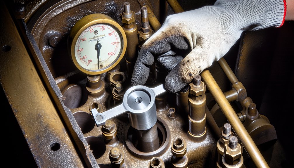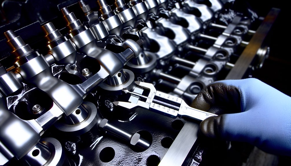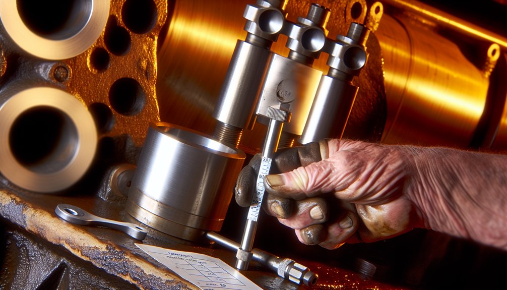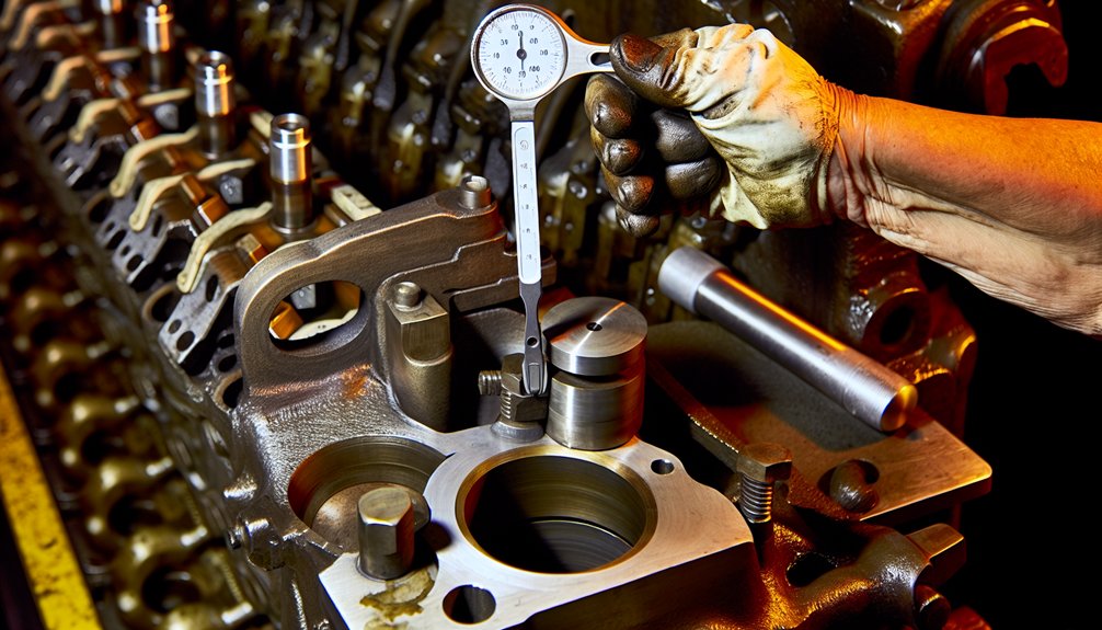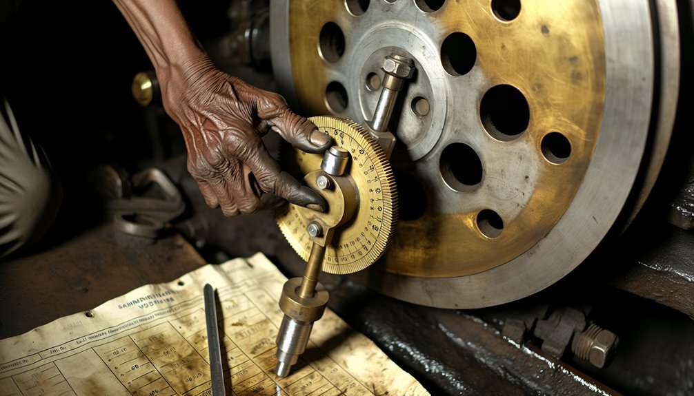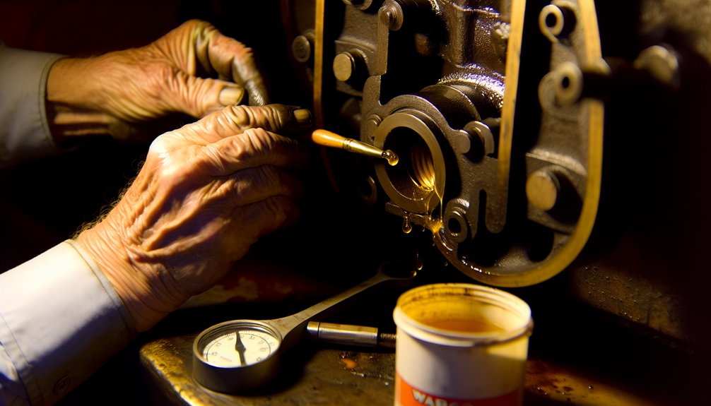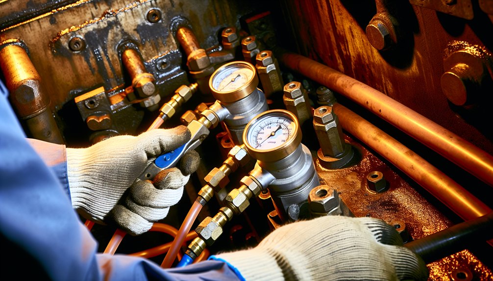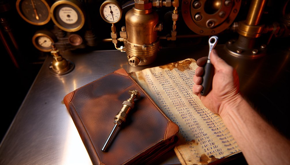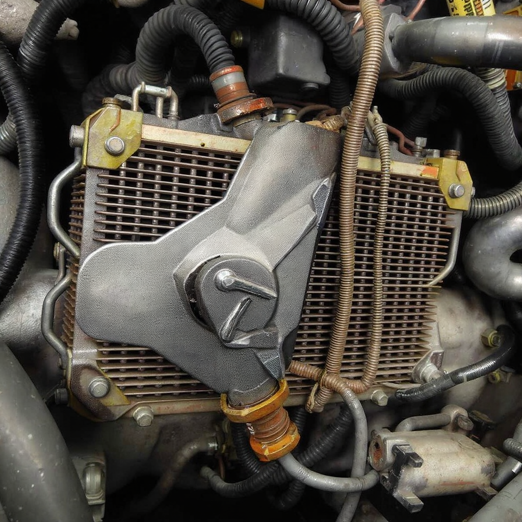
EMD Thrust Washer Replacement: Diesel Locomotive Engine Part

EMD Thrust Washer Replacement: Diesel Locomotive Engine Part

How do you ensure compatibility when replacing an EMD locomotive thrust washer?

Match the engine model, verify part data, and measure end float. The wrong thrust washer can lead to rapid wear, heat buildup, oil starvation, and loss of engine power. We provide a practical solution path to make sure your EMD engine continues to run with top reliability and efficiency on track.

When working with EMD engines and thrust bearing components, follow these key steps to ensure compatibility, correct installation, and reliable operation. Start by confirming the model and component lineage, then verify measurements and assembly details that affect performance.

  1. Match the EMD model family first: EMD 645 vs EMD 710
  2. Verify original part numbers and approved supersessions
  3. Measure crankshaft end float per standard before and after change
  4. Confirm thrust washer material specs for heat and oil compatibility
  5. Check block and bearing cap alignment for front and rear thrust faces
  6. Use OEM drawings and electro-motive diesel service bulletins
  7. Inspect for scoring on thrust surfaces and address root cause
  8. Ensure correct oil clearance and spring-loaded bearing retention
  9. Validate direction of installation: lead-in chamfers to correct side
  10. Source from a trusted exporter like Mikura International

Understanding Issues in Thrust Washers in Diesel Locomotives

Understanding Issues in Thrust Washers in Diesel Locomotives

In a locomotive diesel engine, the thrust washer controls axial movement of the crankshaft. Excess thrust causes damage, heat, and oil degradation that reduce reliability and efficiency. If not corrected early, the issue can break the thrust faces apart. The result is poor efficiency, higher fuel use, and reduced reliability for both industrial and passenger railway operations.

Common Issues Related to Thrust Washers

  • Common issues include improper end float, wrong part selection for the EMD engine model, and contaminated oil.
  • Debris scoring and incorrect materials accelerate wear and heat.
  • Misalignment in the loco block reduces contact area.
  • Front or rear location errors cause uneven thrust.
  • Slow oil delivery at idle worsens damage.
  • Ignoring early vibration signs is not worth the risk.
  • Inspectors should always verify clearances and tolerances against the OEM specifications before assuming the unit is serviceable.
  • Regular oil analysis will catch rising particle counts and viscosity shifts that precede catastrophic failure.
  • Use magnetic plugs and particle counters to monitor ferrous contamination; ferrous wear often signals bearing distress or gear misalignment.
  • When vibration is detected, perform a phased-array or modal analysis to isolate the source — unbalanced rotating assemblies, loose fasteners, or resonance in the frame all produce distinct signatures.
  • Torque values on thrust bearings and bolted joints must be checked at temperature, not cold, to ensure proper preload.
  • Corrective actions include immediate shutdown on detection of abnormal pressure, temperature, or vibration alarms, followed by a borescope inspection of bearing surfaces and journals.
  • Replace suspect bearings with OEM-approved parts and re-establish oil flow paths: clean or replace strainers, verify pump clearances, and confirm relief valve settings.
  • If contamination is present, perform a controlled flush of the sump and cooling passages and recondition or replace filters; simply topping up oil is insufficient.
  • Preventive practices reduce recurrence:
    • Maintain a strict parts-lot traceability program.
    • Establish torque and alignment checklists for reassembly.
    • Implement an oil-change schedule driven by oil analysis results rather than calendar alone.
    • Train crews to recognize early cues — subtle noise changes, minor temperature drift, or brief pressure transients — and empower them to act.
    • Document every inspection and repair so pattern failures are visible; small trends unchecked become major overhauls.

How to Ensure Compatibility When Replacing EMD Locomotive Thrust Washers

How to Ensure Compatibility When Replacing EMD Locomotive Thrust Washers

Compatibility requires accurate identification, measurement, and documentation. Start with the EMD model: EMD 645 or EMD 710. Verify whether the engine is configured for front or rear thrust. Confirm the original part and approved replacement. Make sure the thickness stack matches the standard end float spec. Assess oil system health to ensure proper lubrication. Align the bearing caps and check runout. Use only parts built to the right engineering tolerances for your diesel locomotive.

Key Factors to Consider for Compatibility

Key factors include engine family, thrust face location, and material composition. Confirm the engine build standard and any field service updates. Measure end float with a dial indicator and compare to limits. Evaluate oil viscosity and cleanliness for the service environment. Consider train duty cycle and heat load. Ensure proper chamfer orientation in the direction of rotation. Validate that the component meets electro-motive diesel requirements for load and life.

Identifying the Right Part Numbers

Identify part numbers by cross-referencing the engine data plate and service records. Use the original number and check approved supersessions for your model. Note if the washer set includes front and rear halves with different leads. The best practice is to confirm with engineering drawings. Make sure thickness and oil groove patterns match the specified standard. For commercial buyers, Mikura International can help verify the correct replacement solution.

Consulting Technical Documentation

Consult EMD service manuals, parts catalogs, and technical bulletins for your diesel engine. These documents define end float limits, material specs, and installation direction. Follow torque values, alignment steps, and inspection criteria. Use photos and schematics to ensure proper orientation. Confirm any updates for heavy-duty or passenger service. Document measurements before and after the change. This disciplined use of documentation ensures reliability and longer engine life.

Step-by-Step Guide to Replacing EMD Locomotive Thrust Washers

Step-by-Step Guide to Replacing EMD Locomotive Thrust Washers

This step-by-step guide gives a clear path to replace the thrust washer on an EMD engine. The procedure fits EMD 645 and EMD 710 diesel locomotive models. It helps you ensure correct fit, direction, and end float. Follow the sequence to avoid heat, oil starvation, and early wear. The steps reduce risk of damage to the block and rear or front faces. Use this as a practical maintenance solution to improve reliability, power, and efficiency on track for heavy railway service.
Tools Required for the Replacement

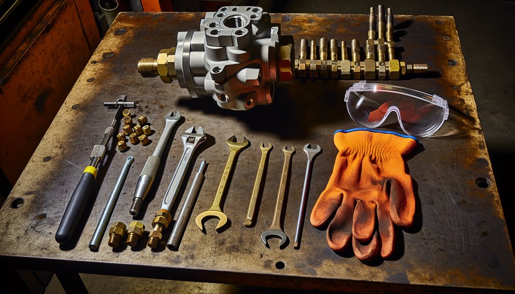
 You will need a dial indicator with magnetic base to measure float. Prepare feeler gauges, a torque wrench, and a micrometer for thickness checks. Use a straightedge, plastigage, and a flashlight to inspect the thrust faces and oil grooves. Have solvent, lint-free wipes, and assembly oil ready. A soft-faced mallet, pry bar, and suitable pullers help with careful disassembly. Keep alignment pins, thread chasers, and marking pens. Use clean trays to protect each component during the change. Select only standard, calibrated tools for consistent results.

PurposeTools/Items
Measurement and inspectionDial indicator with magnetic base, feeler gauges, torque wrench, micrometer, straightedge, plastigage, flashlight
Disassembly and handlingSoft-faced mallet, pry bar, suitable pullers, alignment pins, thread chasers, marking pens, clean trays
Cleaning and assemblySolvent, lint-free wipes, assembly oil

 Optional items improve the work quality. A borescope helps inspect the block and bearing cap in tight areas. Use a paint marker to tag front and rear parts to avoid reverse installation. A low-range torque adapter supports accurate fastener control. A precision straightedge can detect small high spots on the thrust line. A portable heater can warm oil for slow climates. Keep EMD service manuals, torque charts, and electro-motive diesel drawings at hand. These tools ensure a precise and repeatable replacement process.

Preparation Steps Before Replacement

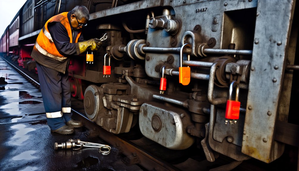
First, confirm the EMD model and the original part number with service records. Make sure the replacement thrust washer matches the engineering build standard. Drain oil to a clean container and filter it to check for metal. Lock out the locomotive and record baseline end float. Remove covers to access the crankshaft thrust location. Clean the surrounding area to keep debris out. Record baseline end float with a dial indicator. Note front or rear thrust placement and the correct direction of the lead-in chamfer.

Inspect the crankshaft thrust faces for scoring, heat marks, or uneven wear. Check the bearing cap alignment and look for any spring-loaded retainer features. Measure the washer thickness and compare to the standard. Review electro-motive diesel service bulletins for updates to the model. Prepare assembly oil and verify oil supply passages are clear. Mark components so they return to the same position if reused. If you need sourcing guidance, Mikura International can help identify the ideal replacement solution with top reliability.

Replacement Procedure Explained

Support the crankshaft to relieve thrust load. Remove the bearing cap at the thrust location. Note the orientation of the existing thrust washer halves, front and rear. Carefully slide the old component out to avoid scratching the block. Clean the cap and block faces with solvent. Check the oil grooves and lead chamfers on the new washer. Match chamfer direction to rotation and oil flow. Lightly coat the surfaces with assembly oil. Install the new halves and seat them flush without forcing the fit.

Reinstall the bearing cap and torque fasteners to the standard values. Rotate the engine by hand to settle the parts. Measure end float and verify within guide limits. Use plastigage if needed to confirm oil clearance. Verify smooth movement with no drag or binding. Prime the oil system and check pressure on first run. Monitor heat, noise, and vibration. Record all measurements in the maintenance log. This disciplined approach ensures performance, efficiency, and longer service life for your diesel locomotive engine.

Maintenance Tips for EMD Train Engine Thrust Washers

Maintenance Tips for EMD Train Engine Thrust Washers

How do you ensure compatibility when replacing an EMD locomotive thrust washer? Control end float and confirm original build data for EMD 645 or 710. The aim is to prevent heat, oil starvation, and early thrust wear. Use disciplined inspection and precise measurement to protect power and reliability in diesel locomotive service on track. This section provides a practical guide to keep your thrust component in spec and extend engine life.

To maintain optimal performance and prevent premature wear, follow these recommendations during service and inspection:

  1. Verify end float at every major service interval.
  2. Match washer material to the oil and heat profile.
  3. Inspect front and rear faces for scoring and lead wear.
  4. Use Electro-Motive Diesel specifications for torque and fit.
  5. Keep oil clean and monitor viscosity and contamination.
  6. Align bearing caps to standard to prevent thrust line mismatch.
  7. Confirm the direction of chamfers to avoid reverse installation.
  8. Document measurements and compare them to model guide limits.
  9. Replace at the first small sign of rapid wear.
  10. Source validated replacements from Mikura International.

Regular Inspection and Monitoring

Schedule thrust inspections with each oil change and valve set on the loco. Trend crankshaft end float readings over time. Inspect the front and rear thrust faces for small lines, heat tint, or uneven contact. Check oil pressure and temperature during run-up to catch slow flow issues early. Review vibration data for axial movement indicators. Confirm bearing cap alignment to the block using a straightedge. Compare readings to electro-motive diesel limits for your engine model and service duty.

Best Practices for Maintenance

Use clean assembly oil and lint-free wipes to protect the thrust surface. Follow the guide torque sequence and standard values to prevent cap distortion. Orient the lead-in chamfer correctly relative to rotation and oil flow. Validate the washer thickness stack to achieve the ideal float range. Keep debris away from the component during change to avoid scoring. Align the cap dowels and check for spring-loaded retainer features. Record all measurements, including before and after numbers, for reliability and performance tracking.

Signs of Wear and When to Replace

Rising end float, heat discoloration, and scoring are early warning signs. Early symptoms include low idle oil pressure impact on axial control, abnormal noise, and slight power loss. Check for metal in oil filters and any scoring on the block contact surface. If the float approaches the upper limit, plan a replacement before the washer wears apart. Replace immediately if you see uneven wear on front or rear halves. Mikura International can supply a validated replacement solution matched to your EMD engine model and duty profile.

Engineering Solutions for Locomotive Thrust Washer Issues

Engineering Solutions for Locomotive Thrust Washer Issues

Engineering solutions focus on controlling end float, heat, and oil flow to protect the EMD engine. Ensure even load sharing across block, cap, and thrust faces. Use electro-motive diesel specifications to guide alignment and torque. Validate the direction of lead chamfers to avoid reverse installation. Address small scoring early to stop wear from growing. This approach boosts power, reliability, and efficiency in railway service.

Innovative Materials Used in Thrust Washers

Modern thrust washer materials blend steel backings with advanced overlays for heat and oil stability. Choose materials matched to model, duty cycle, and oil chemistry. Copper-lead and tri-metal systems resist seizure under high thrust at slow idle. Polymer-modified overlays reduce friction during start and protect the engine when oil is thin. Solid lubricant additives help in short oil starvation events. Engineers match hardness to the crank and block for balanced wear. The best material choice depends on the EMD 645 or EMD 710 model, duty cycle, and oil chemistry. Always ensure compatibility with electro-motive diesel standards.
Advanced Manufacturing Techniques

Precision manufacturing ensures the thrust washer holds tolerance across the thrust line. CNC machining produces consistent thickness and controlled oil groove geometry. Laser texturing improves oil film stability under variable load. Sputter or electroplated overlays add uniform wear layers for longer service. Automated inspection verifies flatness and parallelism for front and rear halves. Controlled heat treatment stabilizes the steel backing against distortion. These methods reduce early run-in wear, support correct end float, and deliver reliable performance on track for industrial and passenger locomotives.

Expert Insights on Thrust Washer Performance

Experts stress three factors: end float control, oil cleanliness, and correct installation direction. Excess float lets the crank move and concentrates load on a small area. That creates heat and accelerates wear. Clean oil keeps debris away from the thrust face and grooves. The lead chamfer must face the intended flow to prevent starvation. Match material to the engine model and build standard. Monitor idle oil pressure for a slow drop that signals risk. Small corrections early prevent parts from wearing apart and protect efficiency.

Recap of Key Points

Mikura Engine Parts - EMD Thrust Washer

Reliability depends on disciplined measurement, correct materials, and precise assembly. Start with the original part data for your EMD 645 or EMD 710 engine. Verify the float, the front and rear washer orientation, and the chamfer direction. Use approved electro-motive diesel limits and torque values. Keep oil clean and aligned to service conditions. This guide gives a practical solution path to improve power and fuel efficiency. For commercial sourcing and engineering support, Mikura International provides validated replacement options for diesel locomotive applications.

Measure crankshaft end float before and after the change to ensure compatibility. Confirm the model, build standard, and original part supersession. Choose the right material for heat and oil profile. Align the block and bearing cap to avoid thrust line errors. Install with correct orientation and lead direction. Monitor oil pressure and temperature during run. Address small scoring early to avoid rapid wear. Follow electro-motive diesel service guidance. These steps raise reliability, maintain power, and extend diesel engine life on track.

Final Thoughts on EMD Locomotive Thrust Washer Maintenance

A thrust washer is a small component with a critical job in the locomotive engine. Its performance hinges on controlled float, clean oil, and precise assembly. The best results come from verifying part data, using calibrated tools, and documenting each service. Keep the washer within standard limits to protect the block and crank. Never ignore early heat signs or a slight vibration. With consistent practices, your EMD engine will run longer, use less fuel, and deliver dependable power for railway operations across heavy duty cycles.

Contact Information for Further Assistance

For technical clarification, replacement verification, or bulk procurement, contact Mikura International. We support EMD 645 and EMD 710 diesel locomotive thrust washer selection and compatibility checks. Our team helps confirm end float targets, material choices, and installation direction for your service duty. Request engineering drawings, tolerance data, and inspection guides. Get a rapid quote and lead time aligned to your maintenance window. Ensure a smooth replacement that meets electro-motive diesel standards and keeps your locomotive reliable and efficient on track.

Prevent Premature Thrust Washer Failure in EMD Locomotive Diesel Engines

Prevent Premature Thrust Washer Failure in EMD Locomotive Diesel Engines

How can you prevent premature failure of an EMD locomotive thrust washer?

Start by controlling axial loads, lubrication quality, and alignment during assembly. Many engine failures begin with small errors in diesel engine operation. These escalate under high-speed duty and heavy load cycles. Focus on clean lubricant, precision engineering, and predictive maintenance. This reduces downtime and maintenance costs and protects critical components. Keep oxidation and corrosion in check. Monitor wear during overhaul. Confirm cylinder head geometry. Validate injector timing and exhaust valve function.

For reliable performance, focus on the following:

  • Use OEM-grade thrust washer alloy.
  • Ensure the correct surface finish.

Verify crankcase oil cleanliness and monitor lubricant oxidation. To make this easier to follow, focus on the following steps:

  • Check the crankcase oil to ensure it is clean and free of contaminants.
  • Monitor signs of lubricant oxidation to detect deterioration early.

– Check misalignment between crankshaft, connecting rod, and bearings.

Control axial loads from the 645 or 710 series power assemblies.

– Maintain proper hydraulic tension and valve train geometry.

– Inspect for abrasive debris after every diesel overhaul.

– Log temperatures to prevent overheat under high-speed duty.

– Conduct metallurgical failure analysis on any removed parts.

Implement predictive maintenance across the fleet. To get started, focus on key actions that make the rollout practical and effective:

  • Identify critical assets and failure modes to prioritize monitoring.
  • Set up data collection from sensors and maintenance logs to feed predictive models.
  • Establish alert thresholds and workflows for timely interventions.

Source parts from Mikura International to ensure reliability.

Understanding Locomotive Thrust Washer Failure

Understanding Locomotive Thrust Washer Failure

In a diesel locomotive, the thrust washer controls axial crankshaft movement under power generation loads. EMD platforms, including 645 and 710 engines, impose significant axial loads during engine operation. Inadequate lubrication, abrasive contamination, or misalignment can lead to premature failure. The washer’s alloy, surface hardness, and oil groove design must match the engine duty cycle. Poor lubricant chemistry accelerates oxidation and corrosion. Overheat conditions degrade film strength and cause bearing wipe. Precision engineering during assembly protects the piston and connecting rod relationship, stabilizing engine performance.

Common Causes of Premature Failure

Misalignment is a prime cause, often introduced during assembly or after an incomplete overhaul. Thin or degraded lubricant films allow metal-to-metal contact and bearing distress. Abrasive particles from worn injectors, cylinder wear, or crankcase debris scar the thrust washer. Excess axial loads from the valve train, exhaust valve events, or power assembly thrust lead to premature wear. Overheat events thin oil and trigger oxidation. Incorrect alloy selection or poor manufacturing technology reduces lifespan. Corrosion from coolant or fuel ingress erodes surfaces. All can lead to premature and unexpected failures.

Impact on Diesel Locomotive Engine Performance

Thrust washer degradation increases axial crankshaft movement, disturbing timing and engine performance. Main bearings lose oil wedge stability, raising friction and heat. Vibration rises and spreads through the cylinder head, injector train, and valve train. Power generation becomes uneven, and fuel efficiency drops. Overheat risk climbs under high-speed loading. Operators see increased downtime and higher maintenance costs, with risk of severe engine damage. Reliability across the fleet declines, shortening service life and forcing unplanned overhaul cycles.

Failure Analysis Techniques

Start with visual inspection for wipe, scoring, and discoloration patterns. Conduct metallurgical and hardness testing to confirm alloy and heat treatment. Use microscopy to detect abrasive tracks and corrosion pitting. Perform failure analysis on oil samples for oxidation, coolant, and fuel dilution. Check geometry for misalignment using runout and endplay measurements. Correlate temperatures and pressure data to identify lubrication loss. Compare wear maps to EMD 645 and 710 specifications. Review assembly records for torque values and precision engineering steps. Use predictive maintenance trends to isolate root causes efficiently.

Preventing Premature Thrust Washer Failure

Preventing Premature Thrust Washer Failure

Manage axial loads, lubrication quality, and assembly alignment to prevent premature failure of an EMD locomotive thrust washer. Predictive maintenance, precise inspection, and correct alloy selection protect bearings and main bearings. Control oxidation and corrosion in the crankcase. Validate injector timing and valve train geometry on every overhaul. Monitor lubricant condition and abrasive contamination during engine operation. Keep temperatures stable under high-speed power generation. Use precision engineering in assembly to protect the piston, cylinder head, and connecting rod interface. These actions raise reliability, extend service life, and cut downtime across your fleet.

Importance of Predictive Maintenance

Predictive maintenance turns random failures into planned interventions. In an EMD diesel engine, it tracks axial loads, endplay, and thrust washer wear before damage spreads to bearings. Oil analysis detects oxidation, fuel dilution, and coolant ingress. Vibration trending flags misalignment and valve train anomalies. Thermal profiling spots overheat zones under high-speed duty. Ultrasonic checks reveal lubricant starvation during engine operation. Data from 645 and 710 engines guides overhaul intervals. This approach lowers maintenance costs and safeguards fleet reliability.

Implementing Preventive Maintenance Strategies

Build a preventive program around inspection discipline and precision engineering. Standardize runout, endplay, and geometry checks during assembly and overhaul. Replace thrust washer and bearing sets based on measured wear, not guesswork. Control cleanliness by filtering lubricant and the crankcase environment. Calibrate injector timing and exhaust valve events to limit axial loads. Verify hydraulic tension and alignment across the valve train. Document torque values for the cylinder head and connecting rod fasteners. Use metallurgical verification for alloy and surface finish. These strategies prevent premature wear, reduce downtime, and extend service life.

Effective Lubrication Practices

Lubrication quality determines thrust washer lifespan. Choose a lubricant that resists oxidation, handles high-speed shear, and protects against corrosion. Maintain target viscosity to preserve oil film on main bearings and the thrust washer. Set filtration to remove abrasive debris from assembly residue and injector byproducts. Keep oil cool to avoid overheat and bearing wipe. Validate flow paths to the cylinder and crankcase galleries. Use routine sampling to guide change intervals and flag contamination. Proper lubrication reduces axial friction, prevents premature failure, and stabilizes engine performance during power generation.

Components Influencing Locomotive Thrust Washer Lifespan

Components Influencing Locomotive Thrust Washer Lifespan

Several locomotive components directly shape thrust washer lifespan in an EMD diesel engine. Bearings, exhaust valve events, and assembly quality modulate axial loads and lubrication stability. The cylinder head, injector timing, and valve train geometry also affect wear. Misalignment and abrasive contamination reduce reliability and raise downtime. Precision engineering, correct alloy selection, and sound manufacturing technology help prevent premature failures. Control oxidation and corrosion in the crankcase. Validate endplay during overhaul for 645 and 710 platforms. Use predictive maintenance to catch early distress and extend service life.

The Role of Bearings in Thrust Washer Performance

Main bearings set the axial control envelope for the thrust washer in a diesel locomotive. Poor lubrication or incorrect oil clearance destabilizes the oil wedge and increases friction. Misalignment between crankshaft and connecting rod shifts axial loads during engine operation. Overheat conditions thin lubricant and trigger oxidation, accelerating premature failure. Bearing wipe and abrasive scoring then lead to premature wear. Confirm geometry, surface finish, and correct alloy pairing during assembly. Sample oil for debris after every overhaul. Coordinate bearing selection with duty cycles on 645 and 710 engines. This preserves engine performance and reliability.

Exhaust Valve Functionality and Its Effects

Exhaust valve events influence axial loads and thrust washer stress in EMD diesel engines. Incorrect lash or hydraulic tension alters valve train dynamics and cylinder pressure balance. The result is higher endplay and unstable lubrication at high-speed duty. Sticky guides or corrosion induce lateral forces that reach the crankcase. Injector timing drift compounds loading during power generation. Overheat at the cylinder head degrades lubricant film and alloy surfaces. Set valve train geometry precisely after each overhaul and trend temperatures/vibration to flag anomalies. This approach helps prevent premature failure and avoids unexpected failures across the fleet.

Assembly Quality and Its Impact on Longevity

Assembly quality defines thrust washer longevity by controlling alignment, torque, and cleanliness. Small errors in runout, endplay, or surface finish can lead to premature wear. Abrasive residue left in the crankcase cuts films under high-speed operation. Incorrect torque on connecting rod and cylinder head fasteners distorts geometry. Choose the right alloy and verify hardness with metallurgical checks. Record precision engineering steps and torque sequences for traceability. Validate lubrication passages and filter integrity before start-up. Apply failure analysis lessons to the next build. These practices reduce maintenance costs and extend service life in every diesel locomotive.

Monitoring and Troubleshooting

Monitoring and Troubleshooting

Reliable monitoring prevents premature failure of an EMD locomotive thrust washer by catching wear before damage spreads. Focus on axial loads, lubrication stability, and misalignment during engine operation. Tie measurements to the duty cycle of 645 and 710 platforms. Combine precision engineering with predictive maintenance to limit downtime. Use failure analysis to verify root causes. Control oxidation and corrosion in the crankcase. Track temperatures and vibration under high-speed power generation. Integrate inspection data with overhaul findings. This safeguards bearings and the valve train while extending service life.

Key Indicators of Locomotive Thrust Washer Wear

Early indicators include rising axial endplay, abnormal crankcase noise, and metallic debris in the lubricant. Trending oil pressure fluctuations under load can expose unstable lubrication. Vibration at specific harmonics hints at misalignment and uneven axial loads. Elevated sump temperatures signal overheat and thinning films at the bearing interface. Copper or tin in oil analysis reveals alloy distress and abrasive scoring. Shifts in injector timing effectiveness and exhaust valve events degrade engine performance. Monitor idle-to-high-speed transitions for noise and pressure dips. Compare readings to EMD 645 and 710 baselines to confirm emerging premature wear.

Using Technology for Early Detection

Deploy vibration analysis to detect misalignment and axial movement impacting the thrust washer. Use ultrasound to find boundary lubrication events before wipe occurs. Infrared thermal scans flag overheat zones near main bearings and the cylinder head. Install endplay proximity sensors to track axial loads during power generation. Oil condition sensors monitor oxidation, fuel dilution, and coolant ingress. Couple data with predictive maintenance software to set alarms and dynamic thresholds. Apply onboard analytics in diesel locomotives across the fleet. Correlate sensor events with injector corrections and valve train adjustments to prevent premature engine failures.

Conducting Regular Inspections

Conduct structured inspections at defined hour intervals and after every overhaul. Measure runout, endplay, and surface condition of the thrust washer and main bearings. Inspect the crankcase for abrasive debris and corrosion. Verify lubrication passages and filter integrity. Check injector spray patterns and reset exhaust valve lash to stabilize axial loads. Confirm torque values on connecting rod and cylinder head fasteners using precision engineering procedures. Record all readings against 645 and 710 specifications. Use metallurgical assessments on removed parts to validate alloy and hardness. These steps reduce maintenance costs and limit unexpected failures.

Best Practices for Long-Term Reliability

Best Practices for Long-Term Reliability

Long-term reliability depends on disciplined assembly, clean lubrication, and continuous monitoring in diesel engines. Standardize procedures across the fleet to reduce variability. Choose the correct alloy and surface finish for the thrust washer. Limit oxidation through timely oil changes and temperature control. Train machinists and technicians on alignment and hydraulic tension best practices. Use predictive maintenance to schedule interventions before premature failure. Maintain detailed records to support failure analysis. Select quality parts from Mikura International to ensure consistency. This approach extends lifespan and enhances engine performance under high-speed duty.

Training for Maintenance Personnel

Training should center on axial load control, lubrication integrity, and misalignment prevention. Teach technicians to interpret vibration and oil analysis for early thrust washer distress. Demonstrate correct measurement of endplay, runout, and bearing clearances. Emphasize injector calibration and exhaust valve settings to balance cylinder pressures. Reinforce precision engineering during assembly, including torque sequences for the cylinder head and connecting rod. Explain corrosion and oxidation mechanisms within the crankcase. Simulate high-speed scenarios to practice rapid diagnosis. Equip the team with checklists aligned to EMD 645 and 710 standards to prevent premature failures.

Documentation and Record-Keeping

Accurate records convert observations into reliability gains. Log axial endplay, oil pressure, and temperature trends at each inspection. Archive oil lab reports for oxidation, metals, and contamination. Record torque values, surface finishes, and alloy certifications from assembly. Track injector timing changes and exhaust valve adjustments with dates and hours. Link vibration spectra to specific duty cycles and loads. Capture overhaul findings with photos for failure analysis. Standardize formats across the fleet to compare locomotives fairly. Robust documentation reduces maintenance costs, guides predictive maintenance, and uncovers small issues before they lead to premature damage.

Collaboration with Experts in the Field

Partnering with experts accelerates root cause resolution and boosts reliability. Engage metallurgical specialists for alloy validation and hardness profiling. Consult vibration analysts to decode axial signatures tied to misalignment and bearing stress. Work with lubricant chemists to optimize oxidation resistance and film strength. Coordinate with experienced machinists for precision engineering during assembly and overhaul. Use insights from EMD 645 and 710 field data to refine inspection intervals. Collaborate with Mikura International for consistent manufacturing quality. Expert collaboration reduces downtime and prevents premature failure across the fleet.

EMD Engine Maintenance: Thrust Washer Repair for Locomotives

EMD Engine Maintenance: Thrust Washer Repair for Locomotives

Can a worn-out EMD locomotive thrust washer be repaired, or does it need to be replaced?

The short answer is: it depends on wear limits, damage type, and end play. Most diesel locomotive fleets can restore service with measured repair, but severe scoring or out-of-spec end play demands replace. This article explains inspection, repair, and when to choose new OEM components, focused on EMD engine maintenance for 567, 645, and 710 models.

Before performing any repair work, ensure proper preparation and inspection steps are followed to protect component integrity and support accurate reassembly. Key checks include:

  • Confirm end play against the EMD manual specification before any repair.
  • Inspect bearing surfaces for scoring, heat spots, and radial wear.
  • Measure crankshaft thrust faces for flatness and size tolerance.
  • Check oil supply paths and filter condition to reduce future wear.
  • Verify connecting rods’ axial freedom and rod side clearances.
  • Identify vibration sources that increase axial load on the crank.
  • Use precision shims only when allowed by the manufacturer.
  • Replace gaskets and seals that could contaminate the bearing surface.
  • Match washer material to the application: steel-backed brass or equivalent.
  • Document all measurements for engineering review and future maintenance.

These steps help ensure reliability, reduce premature wear, and provide traceable data for future maintenance.

Understanding Thrust Washers in EMD Engines

Understanding Thrust Washers in EMD Engines

In an EMD engine, the thrust washer controls crankshaft end play, stabilizing axial load under diesel power. It protects the bearing surface on the crank and the block or cap from direct contact. The component supports rotation alignment, keeping the piston and connecting rods centered in the cylinder and liner. Proper end play preserves compression, valve timing, and fuel delivery precision. In emd diesel models like 567, 645, and 710, correct washer selection, size, and surface finish reduce wear, vibration, and mechanical damage during high load and stroke cycles.

Importance of Thrust Washers in EMD Locomotives

The thrust washer maintains crankshaft axial control so the diesel engine holds specification during power changes. It prevents the crank from moving against the block, which could damage the bearing, ring sealing, and valve train timing. Stable end play reduces mechanical vibration and protects engine components like rods, liners, and the motor-driven accessories. For heavy-duty locomotive duty cycles, proper washer surface, flat geometry, and correct model application reduce friction and heat. Precision fit helps the mechanical engineer plan maintenance intervals, optimize fuel efficiency, and extend overhaul life in emd engine maintenance programs.

In practice, a healthy thrust washer keeps the crankshaft centered while the crank transmits load from pistons through connecting rods. It supports smooth rotation and lowers radial and axial wear on the shaft and bearing cap. Good end play helps the diesel locomotive sustain power without scraping or noise. It also protects the timing gear, valve gear, and the 567 or 710 thrust faces from scuffing. Proper lubrication flow forms a film across the bearing surface, ensuring the washer’s steel or brass layer resists damage and maintains OEM-level performance during long hauls.

Common Causes of Wear in Thrust Washers

Oil contamination, poor filtration, and incorrect viscosity are common starters of wear. Abrasives score the bearing surface, while low film strength lets steel contact steel. Excessive clutch or accessory load can push axial force beyond design, increasing end play. Misaligned connecting rods or crankshaft grind errors create uneven contact. Improper rebuild practices, loose caps, or wrong shim stack alter flat contact and size. Fuel dilution and overheating harm brass layers. Ignored vibration issues in the diesel engine accelerate mechanical wear, damaging the washer and crank thrust faces in the emd engine.

Out-of-spec end play from a worn washer can cascade into larger problems. The crankshaft moves axially, upsetting valve timing and intake and exhaust valves events. Piston alignment shifts, affecting liner wear and compression. Repeated axial hits mark the bearing face, creating grooves that trap debris. A damaged surface increases heat and reduces oil film stability. If not corrected, the crank thrust face may require machine work. At that point, repair options narrow, and replace becomes the safe route. Following the EMD manual and OEM specification helps reduce load-induced wear and supports a reliable rebuild outcome.

Identifying Thrust Washer Wear and Damage

Identifying Thrust Washer Wear and Damage

Field maintenance teams often ask if an emd thrust washer can be repaired or if they must replace it. The answer hinges on measured end play, bearing surface condition, and crankshaft thrust face geometry. Accurate inspection determines whether a controlled repair will restore the diesel locomotive to specification. Early detection reduces damage to engine components, the liner, and the shaft. It also protects compression and fuel efficiency. Use the emd manual, OEM tolerances, and precision tools to assess wear, heat marks, and flatness. Document every measurement to inform engineering decisions and ensure safe application on 567, 645, and 710 models.

Signs of Worn Thrust Washers

Be attentive to signs of progressive wear and damage in the assembly. Key indicators include the following:

  • Rising end play beyond the OEM specification, especially after a rebuild or heavy load cycles
  • Axial knock at idle that fades with power increase
  • Metallic debris in oil filters suggesting brass or steel wear from the washer and crank thrust faces
  • Erratic oil pressure during hot operation, hinting at a compromised bearing surface
  • Changes in valve timing behavior, rough rotation, and vibration under stroke transitions
  • Dark heat spots, scoring, or grooved surfaces observed during partial teardown
  • Increased rod side clearance and unusual crank walk

These observations help pinpoint issues early and guide further inspection or corrective action.

Inspection Techniques for Thrust Washers

Begin with a cold and hot measurement of crankshaft end play using a dial indicator against the crank. Compare readings to the emd diesel manual limits for the specific model, such as 567, 645, or 710. Remove caps to visually assess the washer surface for scoring, pitting, and taper. Use bluing to highlight high spots and verify flat contact. Measure thrust face runout and size with micrometers. Confirm oil passage cleanliness to reduce future wear. Check connecting rods alignment and axial freedom to avoid side load. If surfaces are smooth with minor scratches, a controlled repair may be viable; deep grooves require replace.

Tools Needed for Inspection

Prepare a dial indicator with magnetic base for end play checks on the crank. Use outside micrometers and bore gauges to measure size and geometry of the shaft and bearing locations. Employ straightedges and feeler gauges to verify flat surfaces on caps and blocks. Keep precision stones for light surface dressing when allowed by the manufacturer. Use magnification and dye penetrant to detect cracks on the washer and crank thrust face. Ensure torque wrenches, shim gauges, and clean lint-free wipes are on hand. A calibrated thermometer, oil analysis kit, and inspection light help confirm heat-related wear and lubricant contamination.

Repairing vs. Replacing Thrust Washers

Repairing vs. Replacing Thrust Washers

Deciding to repair or replace a thrust washer depends on measurement, surface condition, and end play. In an emd engine, small wear can be corrected with controlled dressing. Severe damage on the bearing surface or crankshaft thrust face demands replace. Follow the manual and OEM specification for each model. The goal is to restore axial control without risking the crank or liner. Use precise inspection to avoid repeat failures. A poor decision increases load, heat, and vibration. Choose the option that protects compression, valves, and uptime.

When to Repair a Thrust Washer

Repair is feasible when the washer shows light scoring, uniform wear, and intact steel backing. The bearing surface must remain flat, with size within the manual limit. End play should be close to specification after adjustment. Minor heat tint is acceptable if the surface retains hardness. A mechanical engineer can stone high spots with precision and restore surface finish. Connecting rods must move freely without side loading the crankshaft. No cracks, delamination, or deep grooves should appear. Use OEM guidance for allowable dressing depth. Repair only when within documented limits.

When Replacement is Necessary

Replace if end play exceeds maximum after shim removal. Replace if the surface has gouges, pitting, or embedded debris. Any crack, lifted brass layer, or warped geometry requires replace. Replace after a lube starvation event or heavy fuel dilution. Replace if the crankshaft thrust faces are out of flat or show deep damage. Replace if vibration or mechanical misalignment has hammered the washer. Replace in cases where the diesel engine shows axial knock under light load. If the manual forbids repair for a given model, replace.

Cost Analysis: Repair vs. Replace

Repair reduces immediate spend when wear is light and geometry is sound. It saves parts cost and shortens downtime. Replacement costs more upfront but protects the crank and engine components. A failed repair can damage the shaft, ring sealing, and valve timing—forcing a larger rebuild and machine work. Consider oil contamination risk and labor hours. In high-power duty, a new OEM washer may reduce total lifecycle cost. Evaluate emd engine maintenance history, vibration data, and fuel efficiency trends. Choose the path that reduces future failures and preserves compression and rotation stability.

Step-by-Step Guide to Thrust Washer Maintenance

Step-by-Step Guide to Thrust Washer Maintenance

A structured process keeps the locomotive engine within specification and reduces repeat wear. Begin with accurate measurement and clean work. Control debris to protect the bearing. Verify oil supply and filter integrity. Inspect the crankshaft and connecting rods for alignment. Use the correct model parts for 567, 645, 710, or 567b. Record all data for engineering review. Follow the manual torque and sequence during reassembly. Confirm end play after warm-up. This disciplined approach supports reliable power, smooth stroke transitions, and extended service life under diesel load.

Preparing for Maintenance

Secure the locomotive, isolate power, and drain oil to a clean container. Clean the area around the caps to reduce contamination. Gather tools for precision measurement and inspection. Confirm OEM specification for end play and washer size by model. Check gaskets and seals for replacement. Plan for shims if the manufacturer allows adjustment. Inspect oil passages and the filter housing. Prepare lint-free wipes to protect the bearing surface. Assign a mechanical engineer to verify geometry. Stage new washers for immediate replace if repair is not viable. Maintain strict cleanliness to protect the diesel engine.

Repairing Thrust Washers: A Detailed Process

Measure end play cold using a dial indicator on the crank. Remove caps and extract the washer with care. Clean the bearing surface and thrust faces with approved solvent. Stone high spots lightly to restore flat contact. Maintain parallelism to the shaft and avoid creating taper. Verify size and surface finish against the manual. Reinstall and lubricate with assembly oil. Check rotation and end play again. Warm the engine and remeasure hot end play. If values drift beyond limits, stop and replace. Document all steps for emd engine maintenance records and engineering oversight.

Replacing Thrust Washers: Best Practices

Confirm the correct washer part for the emd diesel model and application. Inspect crankshaft thrust faces for flatness before installation. Clean journals, caps, and oil passages. Lubricate the new washer and place it squarely against the seat. Ensure full contact with no debris trapped on the surface. Torque caps to the manufacturer’s sequence. Measure end play and adjust only with approved shim methods. Prime oil system and verify pressure on start. Listen for abnormal mechanical noise during rotation. Recheck alignment of connecting rods. Log measurements and verify that compression, intake, and exhaust valves timing remain stable.

Best Practices for EMD Engine Maintenance

Best Practices for EMD Engine Maintenance

Clean oil, precise inspection, and correct application by model reduce unexpected downtime, protect the crankshaft, and stabilize end play. Keep the bearing surface flat and lubricated to prevent wear and vibration. Control axial load with the right thrust washer size and approved shim methods. Verify geometry after every rebuild. Use OEM specification for each emd diesel platform, including 567, 567b, 645, and 710. Protect the diesel engine with disciplined procedures, accurate measurement, and clean assembly to maintain compression, rotation, and power delivery.

Regular Maintenance Schedules

Set a calendar and running-hour schedule that aligns with the EMD manual and your duty cycle. Perform oil analysis every interval to detect fuel dilution and brass debris. Check crankshaft end play at major inspections. Inspect connecting rods and rod side clearances to reduce axial load. Verify intake and exhaust valves timing after rebuilds. Clean oil passages and replace the filter at each service. Review vibration trends to catch looseness early. Confirm liner condition and ring sealing. Document all size readings. Consistent scheduling stabilizes the diesel locomotive and prevents thrust washer damage.

Recommended Tools and Resources

Use a calibrated dial indicator for end play and a magnetic base for repeatable readings. Keep micrometers, bore gauges, and straightedges for shaft and cap geometry. Apply precision stones to dress minor high spots when the manufacturer allows repair. Employ dye penetrant to find cracks in the washer and crank faces. Maintain torque wrenches and shim gauges for accurate assembly. Reference the OEM specification and emd manual for each model. Use an oil analysis kit and thermometer to track heat and contamination. Reliable tools enable precision, reduce rework, and protect engine components.

Expert Tips for Longevity of Thrust Washers

Control contamination to protect the bearing surface and washer. Warm the diesel engine before heavy load to stabilize oil film. Align connecting rods to prevent side loading on the crank. Keep end play near the center of specification for your application. Avoid excessive shim stacking and follow OEM rules. Monitor vibration and correct loose hardware promptly. Verify crank thrust faces are flat during every rebuild. Use the correct steel-backed brass washer for the emd engine model. Maintain proper viscosity oil. These practices reduce wear, protect compression, and extend the life of the shaft and pistons.

Ensuring Optimal Performance in EMD Locomotives

Ensuring Optimal Performance in EMD Locomotives

Optimal performance depends on precise measurement, clean assembly, and correct parts selection by model. The thrust washer must control end play without scuffing the crankshaft. Oil cleanliness and verified geometry reduce load and radial wear. Follow the manual at every step. Record data for engineering review after each maintenance event. Address vibration quickly to protect the bearing and liner. With disciplined procedures, the diesel locomotive sustains power and rotation stability. Consistency in emd engine maintenance cuts downtime and preserves compression and fuel efficiency over long service intervals.

Recap of Key Maintenance Tips

Measure end play cold and hot and compare to OEM specification. Inspect and keep the bearing surface flat and clean. Verify connecting rods alignment to reduce side load. Monitor oil analysis for brass and fuel dilution. Control shim use per manufacturer guidance. Track vibration and correct mechanical looseness. Confirm crankshaft and cap geometry with precision tools. Use proper washer size for 567, 567b, 645, or 710. Replace gaskets that risk contamination. Document every repair and rebuild step. These actions reduce wear and prevent damage to engine components during heavy stroke cycles. Key checks include:

  • Measuring end play (cold and hot) against OEM specification and inspecting bearing surfaces
  • Verifying connecting rod alignment to minimize side load
  • Monitoring oil analysis for brass and fuel dilution
  • Controlling shim use as guided by the manufacturer
  • Tracking vibration and correcting mechanical looseness
  • Confirming crankshaft and cap geometry with precision tools
  • Using the proper washer size for 567, 567b, 645, or 710
  • Replacing gaskets that pose a contamination risk
  • Documenting every repair and rebuild step to ensure traceability

Final Thoughts on Thrust Washer Care

Thrust washer reliability is earned through cleanliness, precision, and the right parts. Keep the diesel engine’s lubrication healthy and the crank faces flat. Select the washer material and size for the specific emd diesel model. Repair only when surfaces are smooth and within limit; replace when damage or excessive end play is present. Maintain alignment across the crank, rods, and caps. Protect compression by preventing axial drift that upsets valve timing. Consistent attention to detail reduces vibration and extends uptime for the locomotive under demanding load profiles.

How Mikura International Can Support Your Replacement Needs

Mikura International supplies OEM-grade thrust washers and related EMD components for 567, 567b, 645, and 710. We provide application guidance, specification matching, and precision kitting to accelerate rebuilds. Our engineering support helps identify correct washer size and end play targets. We ship clean, ready-to-install parts that protect the bearing surface and crankshaft. Reduce downtime with reliable stock and fast delivery. Partner with us for consistent quality that sustains compression, rotation stability, and power. Get the right washer, shims, and gaskets for your locomotive fleet with confidence.

EMD Engine Thrust Washer: Locomotive Power Component Guide

EMD Engine Thrust Washer: Locomotive Power Component Guide

Unexpected wear on an EMD engine can halt a locomotive and disrupt a railroad schedule. The main pain point is rapid axial and radial movement on the shaft that damages bearing surfaces. This raises fuel use, cuts power, and risks failure. Below are quick actions to stabilize operation and reduce downtime.

To maintain locomotive engine reliability, follow these key inspection and service practices. Start by confirming critical alignments and component conditions, then proceed with parts selection and documentation to ensure long-term performance.

  • Verify axial endplay against AAR and OEM specifications
  • Inspect thrust washer surfaces for scoring and vibration fretting
  • Check oil film integrity near the main bearing and gear train
  • Align the crankshaft and traction motor gear mesh precisely
  • Replace worn engine components with new or remanufactured options
  • Choose thrust washers that meet or exceed OEM standards
  • Balance the blower and turbo to reduce axial loads
  • Use unit exchange programs for faster turnaround
  • Source replacement parts from a trusted supplier of locomotive parts
  • Document measurements to track longevity and reliability

Understanding EMD Locomotive Components

Understanding EMD Locomotive Components

EMD locomotive components form a tightly engineered system that converts diesel fuel into traction motor power. The EMD engine families 567, 645, and 710 use coordinated engine parts like bearings, pistons, power assemblies, blower, and turbochargers. Each component manages heat, load, vibration, and lubrication. A thrust washer is a small but critical component that controls axial shaft movement. When selected to meet or exceed OEM specifications, it safeguards maximum efficiency, reduces fuel consumption, and supports industry standard reliability across the rail industry.

What is an EMD Locomotive Engine?

An EMD locomotive engine is a two-stroke diesel power unit designed for steady torque and high reliability. The emd 567, emd 645, and emd 710 platforms share engineering principles and modular engine components. Power assemblies host the piston, liner, and rings for controlled combustion and exhaust flow. A blower or turbo provides scavenging air. The crankshaft and gear train drive the traction motor through mechanical coupling. Bearings and thrust washers maintain correct shaft position, limiting axial and radial motion for stable power delivery.

Importance of Thrust Washers in Locomotives

The thrust washer protects the engine by controlling axial loads on the crankshaft and related gear components. It keeps bearing clearances within AAR and OEM limits, preventing metal-to-metal contact and surface damage. In EMD engines like the 645 and 710, stable axial control prevents vibration, reduces fuel consumption, and preserves longevity. It also limits wear from turbo and blower load changes. Specifying thrust washers that meet or exceed OEM specifications helps maintain reliability and maximum efficiency.

Key Functions of Thrust Washers

Thrust washers provide axial location for the shaft, complementing main bearing support. They create a controlled oil film across the washer surface to absorb load and prevent scuffing. This component stabilizes gear mesh, protects the motor drive line, and reduces vibration that can damage engine components. In EMD 567, 645, and 710 platforms, an optimized washer material and finish extend longevity. Choosing aftermarket or OEM-grade replacement parts that exceed OEM standards ensures consistent performance.

Types of Thrust Washers for EMD Locomotives

Types of Thrust Washers for EMD Locomotives

Choosing the right thrust washer for an EMD engine is vital for axial control and reliability. The wrong component can accelerate wear, raise vibration, and reduce power. Correct selection reduces fuel consumption and protects bearing surfaces. It also stabilizes gear train alignment and traction motor loading. Below, we break down material choices, size and design, and OEM versus aftermarket options. Each choice should meet or exceed OEM specifications and align with AAR guidelines.

Material Variations and Their Benefits

Material selection defines how a thrust washer handles axial and radial load in an emd engine. Bronze-backed with babbitt overlay offers excellent conformability and low surface scuffing. It forms a stable oil film under diesel engine heat and vibration. Sintered bronze with graphite pockets improves boundary lubrication during start-up. Steel-backed PTFE composites deliver low friction, but need precise oil cleanliness. Nitrided steel faces handle high shock loads from blower and turbo events. For EMD 567, 645, and 710, match material to duty cycle, oil chemistry, and gear train dynamics to extend longevity.

Size and Design Considerations

Size and design must align with the shaft journal, bearing housing, and gear layout of the emd 567, emd 645, and emd 710. Critical factors include thickness, width, oil groove geometry, and chamfer angles. Micro-finish on the washer face improves oil film stability and reduces fretting. Controlled flatness protects the mechanical alignment of power assemblies and crankshaft. Reliefs near oil holes support consistent flow under variable engine loads. Always verify axial endplay with gauges. Select a washer that meets AAR tolerances and OEM specifications.

OEM vs. Aftermarket Thrust Washers

OEM thrust washers offer proven fit and baseline performance across emd locomotive parts. Quality aftermarket can meet or exceed oem specifications and deliver cost and lead-time advantages. Look for controlled metallurgy, traceable heat treatment, certified surface finish, and dimensional reports. Unit exchange programs help minimize downtime for railroad operators. Choose suppliers that validate parts on EMD 645 and 710 platforms under real duty cycles. Mikura International provides new and remanufactured options and a line of new replacement parts that exceeds oem standards, ensuring dependable performance and long-term reliability for locomotive components.

Maintenance and Replacement of Thrust Washers

Maintenance and Replacement of Thrust Washers

Unchecked axial wear on a thrust washer can escalate into bearing failure and locomotive downtime. Act early with precise inspections and oil control to protect engine components and schedule integrity. Use data-driven intervals and certified replacement parts that meet or exceed OEM specifications. Partner with a proven supplier of locomotive components to secure reliability, reduce risk, and keep the railroad schedule intact without costly surprises in the power assemblies.

To ensure optimal engine performance and reliability, focus on these key maintenance and inspection steps, followed by best practices for monitoring and documentation:

  • Measure axial endplay against AAR and OEM specifications
  • Inspect washer surface for scoring, fretting, or discoloration
  • Verify oil pressure and cleanliness across the engine
  • Check gear lash and traction motor alignment stability
  • Balance blower and turbo to limit axial spikes
  • Trend iron counts and silicon in diesel oil analysis
  • Confirm crankshaft runout and bearing crush
  • Use unit exchange for faster replacement parts access
  • Choose washers that meet or exceed OEM standards
  • Document wear, torque values, and endplay history

Signs of Thrust Washer Wear

Early indicators include rising axial endplay beyond AAR limits and metallic glitter in the oil filter. A scored washer surface, dull gray hot spots, or babbitt smear point to oil film collapse. Listen for gear whine that changes with load and turbo speed. Track unstable oil pressure during idle and load changes. Monitor crankshaft position change relative to the bearing housing. Increased blower drive vibration and abnormal exhaust smoke under transient power can also signal thrust washer distress in EMD 567, 645, and 710 engines.

Steps for Proper Maintenance

Start with baseline measurements of axial and radial clearances on the shaft and main bearing. Validate oil viscosity, cleanliness, and temperature for the diesel duty cycle. Inspect washer faces, gear tooth contact, and crankcase ventilation. Balance turbochargers and blower rotors to reduce axial impulses. Verify power assemblies alignment and piston travel symmetry. Apply correct torque on caps and maintain mechanical flatness of housings. Schedule oil analysis and borescope checks. Use certified EMD locomotive parts that meet or exceed OEM specifications.

How to Replace Thrust Washers

Shut down the emd engine and lock out controls. Drain oil to a clean container and remove bearing caps per manufacturer procedure. Measure axial endplay and record values. Extract the worn washer, noting orientation and oil groove geometry. Clean surfaces and check crankshaft thrust faces for wear. Install the new washer that meets AAR and OEM specifications, lubricate, and verify flat seating. Refit caps with calibrated torque. Re-measure endplay to confirm within spec. Prime oil, run at idle, then load, and trend vibration, pressure, and temperature.

Choosing the Right EMD Locomotive Spare Parts

Choosing the Right EMD Locomotive Spare Parts

Wrong emd locomotive spare selection invites repeat failures and lost power. The best path is certified engineering data, proven materials, and documented fit on 567, 645, and 710 platforms. Focus on washer metallurgy, bearing finish, and gear compatibility. Validate that parts meet or exceed OEM specifications. Demand traceability, dimensional reports, and AAR-compliant quality. Mikura International supplies new and remanufactured replacement parts with reliability at the core. We support unit exchange programs to cut downtime and stabilize cost while protecting locomotive components and maximum efficiency in the rail industry.

Factors to Consider When Sourcing Parts

Assess duty cycle, ambient heat, and oil chemistry for the engine. Confirm thrust washer thickness, oil groove design, and surface finish. Match bearing and gear tolerances to the shaft and housing. Validate turbo and blower loads that drive axial movement. Seek dimensional certificates, hardness profiles, and heat treatment records. Ensure compatibility across emd 567, emd 645, and emd 710 designs. Prioritize suppliers with documented AAR compliance, short lead times, and unit exchange options. Choose emd locomotive parts that stabilize power delivery and reduce fuel consumption over the long term.

Quality Assurance and Certification

Quality begins with controlled metallurgy, certified machine processes, and final inspection. Look for ISO-aligned systems and AAR traceability. Demand surface roughness data for washer faces and bearing contact zones. Verify hardness depth, grain structure, and coating integrity. Ensure dimensional conformity for axial endplay targets. Review testing on EMD engine rigs for vibration and thermal cycling. Confirm documentation proves parts meet or exceed OEM specifications. Mikura International provides traceable certifications for a line of new components and remanufactured solutions that protect longevity, reliability, and power consistency.

Cost-Effectiveness of EMD Locomotive Spares

True value is reduced lifecycle cost, not only price. A thrust washer that exceeds OEM standards preserves bearings, gears, and the crankshaft, lowering rebuild spend. Fewer unscheduled stops save fuel and protect the schedule. Unit exchange shortens downtime and cuts labor hours. Aftermarket parts with verified data can deliver strong cost control when certified against AAR criteria. Use performance metrics like mean time between overhaul to justify spend. Mikura International helps align budgets to reliability goals for locomotive components across 567, 645, and 710 platforms.

Engineering Insights on Thrust Washers

Engineering Insights on Thrust Washers

Modern locomotive components demand precise axial control under diesel load cycles. A thrust washer must manage oil film, heat, and vibration. Engineers balance material, surface finish, and groove geometry to stabilize the shaft. They align washer behavior with bearing crush and gear mesh dynamics. In EMD 567, 645, and 710 engines, the washer protects the crankshaft and traction motor drive line. The right component reduces fuel waste and preserves power. Designs that meet or exceed OEM specifications deliver reliability and maximum efficiency for demanding railroad service.

Innovations in Thrust Washer Technology

Recent innovations blend steel-backed structures with engineered overlays for axial resilience. Micro-textured surfaces promote oil retention and lower start-up scuff. Laser machined oil grooves stabilize film thickness across radial and axial load swings. Advanced nitriding increases wear resistance near turbo and blower events. Data-logged testing on emd engine rigs validates durability under thermal shock. Composite layers control vibration and protect gear alignment. For emd 645 and emd 710 platforms, these advances extend longevity. They also reduce fuel consumption and maintain industry standard performance.

Impact of Design on Engine Performance

Design touches every metric of engine performance. Thickness and flatness hold axial endplay within AAR targets. Surface finish sets the oil film that shields the bearing and shaft. Optimized chamfers ease flow from the main oil gallery. Correct washer width stabilizes gear contact under torque. Material pairing with the thrust face guards against hot spotting. In EMD 567, 645, and 710, a matched washer, bearing, and housing eliminate micro-motions. The result is higher power density, less vibration, cleaner exhaust, and reliability that meets or exceeds OEM specifications.

Future Trends in Locomotive Components

Future thrust washers will embed sensing pathways for real-time wear data. Coatings tailored to diesel chemistry will cut friction and heat. Additive manufacturing will tailor groove patterns to engine duty profiles. AI-driven analysis will link washer wear to blower and turbo events. Standardized unit exchange cores will speed replacement across emd locomotive parts. Verification will expand beyond AAR checks to dynamic rig testing. Components that exceed OEM standards will dominate procurement. Railroads will specify traceable metallurgy and predictive maintenance to protect power assemblies and traction motor uptime.

Key Takeaways

Thrust washers are small, yet central to locomotive power and reliability. They control axial motion that threatens bearings, gears, and the shaft. In emd 567, emd 645, and emd 710 platforms, correct design preserves oil film and reduces fuel waste. Selection must meet or exceed OEM specifications and align with AAR limits. Modern materials withstand turbo and blower impulses. Maintenance data reduces vibration and protects engine components. With proven replacement parts and unit exchange, operators sustain maximum efficiency and schedule integrity in the rail industry.

Recap of Thrust Washer Importance

The washer fixes axial position and supports the bearing film under diesel loads. It keeps gear alignment stable and protects the motor drive line. Correct surface finish and geometry preserve oil thickness in heat and vibration. EMD engines rely on this component to save fuel and power. Materials tuned to duty cycles prevent scuff and fretting. Designs that exceed OEM standards ensure longevity and reliability. Regular checks against AAR targets confirm control. The result is consistent performance across 567, 645, and 710 engines.

Final Recommendations for Locomotive Owners

Specify washers that meet or exceed OEM specifications with traceable metallurgy. Match material to oil chemistry, ambient heat, and turbo loading. Verify axial endplay and bearing crush at each service. The following practices support reliability and performance:

  • Balance blower and turbochargers to minimize impulses.
  • Use certified EMD locomotive spare options with dimensional reports.
  • Align gear lash and monitor vibration trends.
  • Choose aftermarket parts validated on 645 and 710 duty cycles.
  • Employ unit exchange to cut downtime.

Track oil analysis, surface wear, and crankshaft movement to maintain maximum efficiency and power.

Contact Information for EMD Locomotive Spare Needs

Mikura International supplies a line of new and remanufactured EMD locomotive parts. Our replacement parts for EMD 567, 645, and 710 engines are certified to meet or exceed OEM specifications. We support unit exchange to reduce downtime and control costs. Contact our engineering team for thrust washer selection, inspection guides, and sourcing. We help railroads align reliability targets with budget goals. Reach out to discuss bearings, washers, and engine components for your fleet. Secure proven parts and protect performance in demanding railroad service.

FAQ

Q: What is an EMD engine thrust washer and why is it critical in locomotive powerplants?

A: An EMD engine thrust washer is a precision-machined bearing surface mounted on the crankshaft or connecting rod assembly to control axial (end) play of the crank. In EMD two-stroke diesel engines used in locomotives, the thrust washer prevents excessive longitudinal movement that can damage bearings, seals, and the engine block. Properly functioning thrust washers ensure crankshaft alignment, reduce wear on mains and camshaft drives, and maintain reliable power transmission under heavy load.

Q: How does a thrust washer differ from a thrust bearing in EMD and similar locomotive engines?

A: Thrust washers are simple flat or profiled steel/bronze inserts that create a sliding surface for axial loads, while thrust bearings (e.g., roller or ball types) use rolling elements to carry thrust. EMD engines traditionally use thrust washers because they provide robust, low-profile axial control suited to large diesel crankshafts and tolerate contamination better than rolling elements. In contrast, some GE or ALCO designs may employ different thrust arrangements; however, the washer concept remains common for its simplicity and serviceability.

Q: What materials are thrust washers made from and what material is standard for EMD applications?

A: Thrust washers for EMD engines are typically made from layered materials: a steel backing with a bronze, babbitt, or copper-lead alloy sliding surface bonded on top. Modern rebuilds may use advanced composite or overlay materials to improve fatigue and seizure resistance. The standard OEM specification for EMD often calls for a bronze-faced or babbitt overlay on a steel backing to balance load capacity, conformability, and corrosion resistance—materials chosen to be compatible with oil film lubrication used in locomotive engines.

Q: What are the common failure modes of EMD thrust washers and how can they be diagnosed?

A: Common failure modes include wear from inadequate lubrication (leading to increased end play), scoring or seizure from contamination, thermal distress from oil breakdown, and uneven wear due to misalignment. Diagnosis involves measuring crankshaft end play, inspecting washer faces for grooves, discoloration, or flaking during teardown, checking oil filtration and presence of metal debris, and reviewing operating logs for overheating or lubrication interruptions. Early detection via routine inspections and oil analysis reduces catastrophic failures.

Q: How often should thrust washers be inspected or replaced during an EMD engine overhaul?

A: Thrust washers should be inspected at every major overhaul or whenever the crankshaft is removed. Typical practice is to replace washers whenever wear exceeds OEM limits or if surfaces show pitting, scoring, or thermal damage. For heavy-usage locomotives, inspections may be scheduled based on service hours and oil analysis trends rather than calendar time. Following EMD overhaul manuals ensures correct tolerances; many shops replace washers proactively during top-end or bottom-end rebuilds to restore original crank end play.

Q: Are EMD thrust washers interchangeable with components from ge or alco engines?

A: No, thrust washers are generally engine-family specific. EMD, GE, and ALCO engines have different crank designs, bearing widths, and axial load requirements, so washers are not directly interchangeable. While materials and design principles are similar, correct fitment, thickness, and face profile must match OEM specifications. When servicing mixed fleets, always source washers that match the specific engine model and serial number to ensure proper axial clearance and performance.

Q: What installation best practices should be followed to ensure proper performance of EMD thrust washers?

A: Best practices include cleaning and inspecting crank journals and housing faces, checking mating surfaces for burrs or distortion, pre-lubricating washer faces with the correct oil, installing washers to specified orientation and torque sequences, and measuring axial clearance with a dial indicator to confirm OEM tolerances. Use new hardware and follow torque values. After assembly, perform initial break-in under controlled conditions and monitor oil pressure and end play to ensure stable operation.

Q: Can modern materials or aftermarket thrust washer designs improve longevity in EMD locomotives?

A: Yes, modern materials and improved manufacturing techniques can extend service life. Upgraded overlay alloys, enhanced heat treatments, and precision grinding can increase wear resistance and reduce creep. Some aftermarket suppliers offer engineered composite overlays or improved backing steels that resist fatigue and corrosion better than older designs. However, any upgrade must be validated for compatibility with EMD oil chemistry, crankshaft metallurgy, and operating conditions; shop experience and field trials are recommended before fleet-wide adoption.

Can the Grid Box be retrofitted or upgraded in older EMD locomotives?

Can the Grid Box be retrofitted or upgraded in older EMD locomotives?

Maintenance leaders ask if a grid box retrofit is feasible and worth it. Aging diesel-electric locomotives face heat, reliability, and control issues that hurt productivity. The main pain point is unplanned failures under dynamic braking or high-grade freight duty. This section gives quick wins to stabilize older locomotives while planning a larger retrofit project.

To ensure safe and efficient operations, focus on verifying key aspects of dynamic brake performance under load. The following steps provide a clear sequence to follow:

  1. Audit the dynamic brake performance on each locomotive while operating under load.
  2. Document test results for each unit, noting any deviations or issues identified.

During high-speed shunting, monitor critical components to ensure safety and performance. Specifically, you should:

  1. Thermograph the grid
  2. Thermograph the resistor banks

To ensure reliable operation, carry out the following checks:

  1. Inspect diode racks for cracks.
  2. Check shunt links for any signs of cracking.
  3. Examine excitation wiring for cracks.

– Clean and retorque high voltage terminals and frames.

Upgrade fans and ducts to increase airflow across grids.

– Calibrate throttle-to-brake transition logic in the control system.

– Replace weak contactors and solid state modules proactively.

– Verify cab indications for grid overtemp and wheel slip events.

– Log data from traction motors and alternator during brake tests.

– Establish idle and charge procedures to protect batteries and compressors.

Understanding the Grid Box in Diesel Locomotives

Understanding the Grid Box in Diesel Locomotives

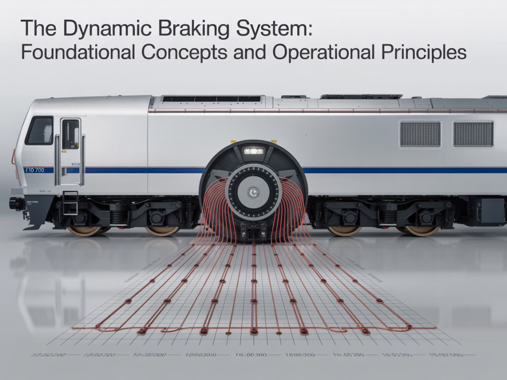
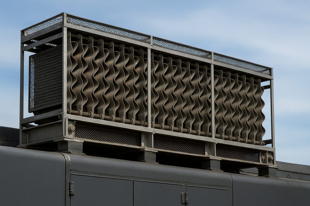
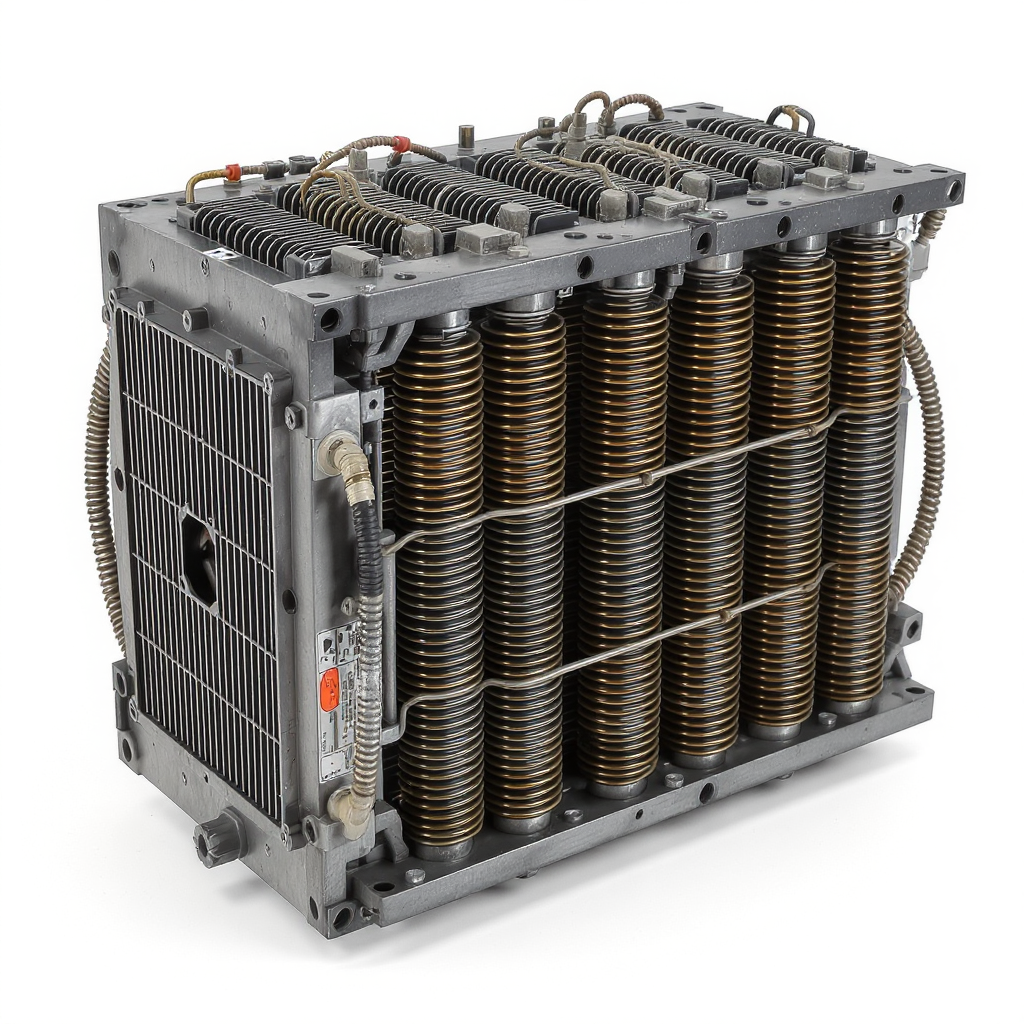
The grid box is the dynamic brake heart of diesel locomotives. During downhill or throttle-off braking, traction motors convert kinetic energy into electrical energy. That energy flows from the generator or alternator through high voltage paths into resistor grids. The grids dissipate heat, allowing controlled braking without air brake wear. In older locomotives, the grid assembly includes resistor elements, blowers, ducts, diode bridges, shunt wiring, and excitation control. The control system modulates current to maintain wheel adhesion on rail. Proper airflow, electrical integrity, and calibration protect the carbody and engine room. A healthy grid reduces brake shoe use, improves reliability, and supports safety and productivity.

Functionality of the Grid Box

In a diesel-electric locomotive, traction motors act as generators during braking. Their output feeds the grid through contactors and a solid state controller. The resistor stack converts electrical energy into heat, which blowers remove. Voltage and current are balanced to prevent wheel slide on wet rail. The excitation system limits peaks when speed changes rapidly. Diode arrays protect against reverse currents. Shunt circuits adjust braking effort at low speed. Sensors report temperatures to the cab, enabling the crew to manage the throttle and brake lever. Modern upgrades add better airflow, fault logging, and AC traction compatibility for more stable control. The result is stable control, lower environmental impact, and extended fleet service life.

Common Issues with Older Grid Boxes

Older locomotives face outdate problems in the grid area. Resistor elements crack, leading to uneven current paths and hotspots. Blowers lose efficiency, so grids overheat and derate. Diode failures cause intermittent braking in dc locos. Wiring insulation in the engine room becomes brittle from heat. Frames and mounts loosen, creating vibration and faults. Solid state cards drift, confusing excitation and shunt control. The cab may show spurious alarms while traction motors see voltage spikes. Airflow ducts clog with dust and oil, and compressors work harder as the air brake compensates. These issues raise downtime and reduce operating margins; timely retrofit can significantly reduce failures in 25-year-old fleets.

Retrofitting Options for Older EMD Locomotives

Retrofitting Options for Older EMD Locomotives

Most railroad operators fear that an aging grid will fail on a grade. The main pain point is balancing budget and downtime while improving safety. Retrofitting stabilizes dynamic braking and reduces operating risk. Use a phased retrofit project to convert critical components first, then expand. This section outlines practical upgrade paths for diesel-electric locomotives and EMD loco platforms.

Prioritize thermal management upgrades to protect the grid and frame.

– Replace weak blowers and ducts to increase airflow across resistor banks.

– Add solid state protection for voltage spikes from traction motors.

– Rewire high voltage leads and shunt links with modern insulation.

– Update the control system logic for brake-to-throttle transitions.

– Fit advanced temperature sensors for carbody and grid monitoring.

– Use sealed diode modules to improve reliability in dusty engine rooms.

– Calibrate excitation to match alternator and generator characteristics.

– Log data in the cab to validate each modification step.

– Align battery charge and idle policies with new electronics.

What is Retrofitting?

Retrofitting is the targeted modification of a diesel-electric locomotive to extend service life. It replaces or upgrades the grid, blowers, diode racks, shunt wiring, and control system without redesigning the entire chassis. The goal is to reuse structure while inserting new technology focused on the dynamic brake path. It may add ac-compatible modules, improved excitation control, and better thermal sensors. The locomotive’s engine, alternator, and cab wiring are inspected for electrical integrity. Retrofitting can comply with updated railway standards and reduce environmental impact by optimizing braking energy conversion.

Key steps in a retrofit project include baseline testing, component selection, installation, and validation on rail. Baseline and validation on real grades are essential to prove performance and reliability. Component selection compares blower curves, diode ratings, and solid state controller features. Installation addresses mounting on the carbody frame, routing in the engine room, and high voltage clearances. Validation uses repeated downhill runs, throttle transitions, and air brake blending. A good plan will significantly reduce failures in old locomotives without a full conversion to a new locomotive platform.

Benefits of Retrofitting the Grid Box

Upgrading the grid assembly delivers immediate reliability gains. New resistor elements distribute heat evenly, so hotspots shrink and panels last longer. High-efficiency blowers raise airflow, keeping grid voltage and current within safe limits. Solid state modules improve excitation and shunt control during rapid speed changes. Sealed diode packs stabilize dc locos under high-speed braking. The cab gets clearer alarms, helping the crew manage brake effort and throttle. These changes reduce reliance on the air brake, cutting compressor load and wear. Operators see fewer derates on steep rail, better productivity, and safer handling in wet conditions.

Retrofitting also supports compliance and cost control. Modern control systems integrate data logging, so the railroad can audit dynamic braking across the fleet. Smart logic can limit charge draw from the battery, preserve alternator health, and protect the locomotive’s engine. Optional ac traction interfaces enable mixed consists with newer electric motors. Improved wiring and insulation protect the chassis and carbody from heat and vibration. The net effect is reduced downtime, extended asset life, and lower total cost per train-mile. For export-grade parts and kits, Mikura International supplies matched components and technical guidance for EMD retrofit programs.

Challenges in Retrofitting Older Loco Models

Older locomotives present integration hurdles that require careful planning. Carbody space is tight, so new blowers and ducts must fit existing frames. Wiring paths in the engine room may not meet today’s high voltage clearance rules. Control system cards can be outdate, making software calibration tricky. Different generator or alternator variants affect excitation tuning. Shunt and diode layouts vary across dc locos, complicating standardization. Some chassis mounts are fatigued, so vibration can damage fresh electronics. Wheel adhesion on worn rail adds uncertainty to test results. Each issue is manageable with a structured engineering review and staged trials.

Supply and documentation gaps add risk. Drawings for an old locomotive may be incomplete, so onsite surveys are essential. Parts interchange between freight, switcher, and passenger variants is not always clean. Emission rules and safety codes change, and the retrofit must comply without a full downgrade of performance. Regenerative braking is often not feasible without a compatible transformer or ac conversion, so expectations must be set. Budget constraints limit scope, making prioritization vital. Early supplier partnership helps align parts, certification, and sequencing to reduce rework.

Upgrading Technology in Older Diesel Locomotives

Upgrading Technology in Older Diesel Locomotives

Older locomotives struggle with heat, unstable brake effort, and outdate control logic. These issues reduce productivity and raise risk on rail. The goal is a retrofit that inserts new technology without a full conversion. Focus on grid, blowers, control system, and wiring inside the engine room. Target the locomotive’s engine interfaces, alternator output, and traction motors. Upgrade paths should reuse the chassis and carbody while boosting reliability. AC traction compatibility can be added with careful excitation changes. A staged retrofit lets operators manage downtime and cost on mixed fleets. Each loco gets measured, modified, and validated under freight and passenger duty.

– Map existing grid wiring, diode paths, and shunt links under high voltage rules.

Replace resistor elements with high-stability units to reduce hotspots.

– Fit variable-speed blowers tied to grid temperature for better airflow.

– Install solid state protection to guard traction motors and generator.

– Update control system logic for throttle transitions and wheel adhesion.

– Add cab data logging for brake current, voltage, and temperature trends.

– Rewire with modern insulation to protect the frame and chassis.

– Balance battery charge logic to avoid idle overdraw and compressor strain.

– Validate on rail with downhill tests, air brake blending, and high-speed runs.

– Document compliance with railway safety and emission-related electrical standards.

Latest Technologies for Grid Box Upgrades

Modern grid technology lets a diesel-electric locomotive brake harder and cooler. High-dissipation resistor banks distribute heat evenly across the grid. Variable-frequency blowers raise airflow when voltage and current peak. Solid state excitation modules stabilize braking when speed changes. Smart diode modules protect dc locos from reverse currents. Sensors in the engine room stream temperature and vibration into the cab. The control system then tunes shunt and brake effort to maintain traction on wet rail. AC traction-ready interfaces allow consists with electric motors in new locomotives. Edge logging captures brake energy to support maintenance and compliance. These upgrades cut thermal stress and unplanned stops across the fleet.

Comparative Analysis of Upgraded vs. Original Systems

Original systems on old locomotives use fixed-speed blowers and coarse control. Upgraded loco packages deliver precise excitation and airflow. The result is steadier grid voltage, less wheel slip, and longer component life. Resistor life improves, and the frame sees fewer heat cycles. Battery charge is managed, so idle time drops and the compressor runs less. Cab indications become clearer, aiding the crew during freight and passenger moves. Air brake wear falls as dynamic brake carries more load. Operators see fewer derates on long rail grades. The retrofit also prepares for mixed consists with ac traction. Overall, reliability rises and total cost per train-mile trends down.

Cost Considerations for Upgrades

Budget for a retrofit by splitting costs into hardware, labor, testing, and downtime. Hardware includes resistor grids, blowers, diode modules, sensors, and control system cards. Labor covers engine room rewiring, mounting on the carbody, and calibration. Testing includes rail trials for brake current, excitation limits, and wheel adhesion. Downtime planning reduces impact on train schedules. Savings come from reduced failures, lower air brake wear, and lower idle fuel. Avoid a downgrade in performance by matching alternator and generator ratings to the new modules. Plan spares for resistor elements and solid state cards. Mikura International can supply matched kits that comply with railway standards and support predictable installation windows.

Practical Tips for Retrofitting and Upgrading

Practical Tips for Retrofitting and Upgrading

Unplanned dynamic brake failures in older locomotives hurt timetables and margins. Prioritize grid, control system, and airflow upgrades, and validate under real duty. Use components that comply with railway standards. Align alternator, generator, and excitation to avoid a downgrade. Protect traction motors and battery health. Manage cab indications for the crew. Document voltage, current, and temperature. Prioritize parts with proven reliability.

– Define retrofit scope by failure modes in diesel-electric locomotives.

– Map high voltage paths before any modification work.

– Benchmark brake current and grid temperature on a test train.

– Select resistor, diode, and solid state modules with matched ratings.

– Fit variable airflow to stabilize the grid under high-speed duty.

– Update control system logic for throttle transitions and wheel adhesion.

– Verify battery charge policies to protect the compressor and idle fuel.

– Validate on freight and passenger profiles across wet and dry rail.

– Train crew to interpret cab alarms and data logs.

Stage the retrofit to reduce downtime while de-risking the fleet.

Step-by-Step Guide to Retrofitting

Start with a baseline survey across the fleet of older locomotives. Inspect the carbody, chassis mounts, and frame for heat fatigue near the grid. Record alternator and generator data under brake and throttle transitions. Thermograph resistor banks and ducts at several rail speeds. Next, design the retrofit around reuse of mounts and engine room clearances. Select resistor elements, diode modules, and solid state excitation that match electrical limits. Install variable-speed blowers to control airflow with temperature and voltage. Rewire shunt links with modern insulation for high voltage compliance. Finish with cab calibration, data logging, and downhill validation runs.

Choosing the Right Components for Upgrades

Component selection determines retrofit reliability. Prioritize resistor banks with stable ohmic values at temperature. Choose sealed diode packs for dc locos to prevent dust failures. Specify solid state excitation with fast response to traction changes. Match blower curves to grid dissipation and carbody ducting. Ensure the control system can interface with ac traction if required. Align alternator and generator voltage limits with new modules. Use sensors rated for the engine room environment. Validate connectors for vibration on long freight duty. Confirm software supports wheel slip logic and cab alerts. Select parts that comply with railway codes and emission-related electrical rules.

Expert Insights on Successful Retrofitting

Experienced railroad teams plan around the locomotive’s engine interfaces first.

  • They verify excitation behavior during throttle cut and brake onset.
  • They protect traction motors with surge limiting and fast shunt control.
  • They place temperature sensors near hotspot zones in the grid.
  • They log current and voltage at the cab for every trial run.
  • They avoid a conversion path that requires a transformer unless ac traction is the goal.
  • They stage installations across representative loco variants, including switcher and passenger units.
  • They guard against battery abuse during tests and idle.
  • They document clear acceptance limits to prevent scope creep.

Keeping spares for resistor and control cards avoids extended downtime.

Future of EMD Locomotive Technologies

Future of EMD Locomotive Technologies

Retrofitting the grid and control system extends locomotive life and stabilizes braking. Operators see fewer derates on rail grades and better productivity. Data logs help the crew manage brake and throttle transitions. Air brake wear drops as dynamic brake carries more load. Battery and compressor life improve with smarter charge logic. By reusing the chassis and carbody, capital outlay falls. Reliability gains reduce operating risk across the rr fleet. This path also prepares for optional AC traction interfaces without full conversion. The result is safer trains and stronger margins.

Long-term Benefits of Upgrading

Lower failure rates and predictable maintenance drive long-term value. Balanced voltage and airflow extend resistor life and frame integrity. Smart excitation reduces wheel slip and protects traction motors. Control updates cut spurious cab alarms, helping the crew focus. Battery charge control reduces idle time and compressor cycling. Rail safety improves with stable braking on wet rail. Operators avoid a costly downgrade to performance while meeting compliance. Mixed consists with new locomotives become easier with ac-compatible interfaces. Strategic spares reduce downtime during peak freight windows. These gains compound over years and significantly reduce total cost per train-mile.

Future Trends in Locomotive Technology

Future EMD-oriented upgrades will tighten integration between control system and grid health. Edge analytics will track brake energy and thermal cycles in real time. AC traction support will expand without forcing full conversion. Smarter shunt control will improve adhesion at low speed. Regenerative braking options may emerge with corridor infrastructure, but most fleets will dissipate to grid. Modular solid state racks will simplify swaps in the engine room. Diagnostics will shift to predictive alerts in the cab. More components will comply by design with evolving railway electrical rules. These trends reduce operating risk while sustaining older locomotives.

Final Considerations for Railroad Operators

Define clear retrofit goals and align parts to alternator/generator limits. Approach high voltage changes with strict procedures and audits. Budget for testing time on real rail, not only bench work. Train the crew on cab data and wheel adhesion logic. Plan spares and documentation to sustain the fleet. Avoid overreach, such as transformer-heavy conversion, unless ac traction is mandated. Validate against safety, electrical, and emission-related rules. Use suppliers who guarantee matched kits and technical support. Mikura International provides export-grade components and guidance that shorten installation windows and raise reliability.

FAQ

Q: Can the Grid Box be retrofitted into older EMD locomotives?

A: Yes. Many older EMD models can accept a Grid Box retrofit, but feasibility depends on the specific model, available space, cooling capacity, and the condition of the existing electrical and control systems. A detailed engineering assessment is required to verify mounting, wiring, and integration with the locomotive’s power electronics and safety systems.

Q: What differences arise when retrofitting a Grid Box into a diesel engine-powered EMD versus an electric locomotive?

A: Retrofitting a Grid Box into a diesel-engine EMD primarily involves integration with the prime mover’s alternator/generator, excitation systems, and engine control unit. For an electric locomotive, the retrofit would focus more on compatibility with the high-voltage traction supply and auxiliary converters. Diesel-electrics often require additional cooling and vibration isolation, while electric locomotives may need different insulation and filtering to match system voltages.

Q: How long does a typical Grid Box upgrade take for an older EMD unit?

A: Project duration varies with scope. A basic swap and wiring integration can take a few weeks per locomotive if parts and documentation are available. Complex retrofits involving structural changes, software integration, and extensive testing often take several months. Lead times for parts and testing schedules with regulatory bodies (especially for passenger operators like Amtrak) can extend timelines.

Q: Are there age limits—such as locomotives older than 25 years—where retrofitting becomes impractical?

A: Age alone (for example, 25 years) is not an absolute barrier, but locomotives older than 25 years often present additional challenges: obsolete control electronics, metal fatigue, wiring degradation, and lack of manufacturer documentation. A cost-benefit analysis typically compares retrofit cost against remaining service life and reliability; beyond a certain age, replacement may be more economical.

Q: Will retrofitting a Grid Box improve reliability and performance on Amtrak or commuter fleets?

A: Properly integrated Grid Box retrofits can improve power conditioning, fault tolerance, and control responsiveness, which enhances reliability and can reduce downtime. For passenger operators such as Amtrak and commuter agencies, benefits include better traction control, improved diagnostics, and potentially reduced fuel consumption. Benefits depend on system-level integration and maintenance practices.

Q: What regulatory or certification steps are required for Grid Box retrofits on revenue-service locomotives?

A: Retrofits must comply with applicable national and regional railroad regulatory standards, safety certifications, and sometimes OEM warranties. Passenger carriers like Amtrak may require FRA (or equivalent) approvals, testing protocols, electromagnetic compatibility verification, and documentation of fail-safe behavior. Coordination with inspectors and submitting test reports is typical.

Q: What are the primary technical challenges when installing a Grid Box in an older EMD frame?

A: Key challenges include mechanical mounting and space constraints, thermal management and adequate cooling, electrical compatibility with legacy alternators and control systems, software and communication integration, and ensuring protection against transients and harmonics. Addressing these requires detailed drawings, possible fabrication of adapters, and updated cooling and grounding arrangements.

Q: How should railroads assess whether to retrofit an older EMD locomotive or replace it outright?

A: Railroads should perform a lifecycle cost analysis comparing retrofit costs (parts, engineering, downtime, testing) against acquisition of newer units. Consider asset condition, expected remaining service life, maintenance records, fuel efficiency improvements from the Grid Box, and operational benefits. Include intangible factors such as fleet commonality and regulatory timelines when deciding between retrofit and replacement.

How does the Grid Box contribute to energy efficiency in locomotive operations?

How does the Grid Box contribute to energy efficiency in locomotive operations?

Operators struggle with high energy consumption, rising diesel fuel costs, and inconsistent power quality on the rail. The grid and traction network can waste braking energy. Substation limits cap maximum power for electric trains. Regenerative braking energy often goes unused. A compact Grid Box helps save energy and stabilize the railway power system.

Key Capabilities and Benefits

CapabilityBenefit
Capture and store braking energy with an energy storage systemUse regenerative braking even on weak railway lines
Smooth power flow between the overhead line and traction motorsImprove voltage stability in the traction power supply
  • Lower fuel consumption in diesel and hybrid locomotive fleets
  • Reduce peak demand at the substation connection
  • Support wayside energy storage for urban rail and transit systems
  • Enhance energy management with real-time analysis of energy consumption
  • Integrate renewable energy sources with the electrical grid
  • Extend component life by mitigating power quality issues

Understanding the Role of Grid Boxes in Energy Efficiency

Understanding the Role of Grid Boxes in Energy Efficiency

The Grid Box is a modular power system interface that links the locomotive, the traction power supply system, and optional wayside energy storage. It manages power flow among the power grid, onboard converter, and traction motor drives. By absorbing regenerative braking energy, it prevents waste and reduces energy consumption. It stabilizes voltage in both direct current and alternating current traction networks. It also buffers short spikes in maximum power demand. In electric locomotive operations, it optimizes supply power from the overhead line and substation. In hybrid or diesel-electric fleets, it supports an energy storage system to electrify auxiliary loads and save fuel. The result is measurable efficiency and better railway power reliability.

Importance of Energy Efficiency in Locomotive Operations

Energy efficiency is a strategic lever for every railway system. Lower energy consumption cuts operating costs for freight train and urban rail services. Efficient traction power lowers diesel fuel burn and reduces emissions. Stable voltage improves power quality and protects traction equipment. Better use of regenerative braking reduces heat and brake wear. Smarter energy management defers costly substation upgrades. Operators can store braking energy and redeploy it for acceleration, reducing peak loads on the traction power supply. A Grid Box enables analysis of energy consumption at the train and network level. That data drives continuous improvement. For buyers with commercial intent, these gains translate to fast payback and greater network capacity.

How Grid Boxes Enhance Energy Storage Systems in Locomotives

A Grid Box coordinates the energy storage system with traction power and electric power interfaces. It controls bidirectional converter stages that charge during braking and discharge during traction. It balances power flow to maintain overhead line voltage and protect the substation. In electric trains, it enables regenerative braking even when the traction power supply cannot absorb energy. In diesel-electric locomotives, it reduces fuel consumption by supplying acceleration bursts from stored energy. The system supports both direct current and alternating current railway lines. It can scale from hundreds of kW to multi-MW applications. Integrated energy management ensures safe limits, high efficiency, and reliable service across the railway system.

Impact on Energy Consumption in Locomotive Operations

Impact on Energy Consumption in Locomotive Operations

High traction energy consumption erodes margins in freight train operations. Operators face diesel fuel volatility, substation constraints, and unused regenerative braking energy. Voltage instability hurts power quality and asset life. A Grid Box can capture braking energy, smooth power flow, and electrify auxiliaries to save energy. It also enables analysis of energy consumption and better energy management across the railway system.

Map traction power peaks by corridor and time to target savings

To approach this effectively, focus on the following:

  • Identify peak power usage by corridor
  • Analyze peak times to understand demand patterns
  • Align insights with targeted savings opportunities

Use regenerative braking on weak railway lines with buffered energy

This approach focuses on capturing braking energy and reusing it efficiently, especially on lines with limited power capacity. Key actions include:

  • Implement regenerative braking systems to recover energy during train deceleration.
  • Add energy buffers to stabilize the network and store surplus energy for later use.

Reduce diesel fuel burn by powering acceleration from storage

– Stabilize voltage at the overhead line to protect converters

– Shift demand away from maximum power windows at the substation

– Deploy wayside energy storage near load pockets on urban rail

– Integrate renewable energy sources via the power grid connection

– Audit power flow to cut idle losses and parasitic loads

– Set MW caps and enforce with the traction power supply system

Analysis of Energy Consumption in Freight Trains

Freight train energy consumption is driven by train mass, gradients, speed profile, and traction motor efficiency. Start-stop cycles on busy rail corridors cause spikes in traction power and wasted braking energy. A Grid Box enables granular analysis of energy consumption to locate losses and quantify savings from storage. Operators can correlate overhead line voltage, converter efficiency, and power flow to locate losses. Results often show high return from capturing regenerative braking energy on long downhill runs and reveal idle electric power draw at yards. With this data, buyers can prioritize sections where grid constraints and substation limits inflate costs.

Comparing Diesel and Electric Locomotives

Diesel and electric locomotive fleets face different constraints, yet share the same goal: reduce energy consumption without harming throughput. Diesel traction benefits from storage-assisted acceleration, cutting fuel use and heat. Electric trains rely on traction power from the overhead line and can recover braking energy when the traction network and substation accept it. A Grid Box buffers regenerative energy and stabilizes voltage on DC and AC lines. The result is higher energy efficiency and fewer maximum power excursions.

Wayside Energy Storage and Its Benefits

Wayside energy storage places capacity on the rail network near high-demand nodes. It captures braking energy from passing trains and returns it during the next acceleration. This reduces peak traction power at the substation and improves rail voltage stability. A Grid Box coordinates power flow between the traction power supply, energy storage system, and electrical grid. Benefits include fewer feeder upgrades, improved use of regenerative braking, and lower line losses. Storage can be scaled from hundreds of kW to multi-MW for DC or AC lines to save energy efficiently.

Technological Innovations in Locomotive Grid Systems

Technological Innovations in Locomotive Grid Systems

Most operators ask how to cut energy consumption without hurting timetable reliability. The answer lies in smarter traction power interfaces, better storage, and clean power flow. A modern Grid Box links the railway, overhead line, and traction network to capture regenerative energy and stabilize voltage. These innovations boost energy efficiency and reduce diesel fuel costs.

– Deploy energy storage systems to capture braking energy

– Use regenerative braking on weak railway lines with buffered power

– Improve power quality with active converters and filters

– Stabilize overhead line voltage to protect traction motors

– Limit maximum power at the substation with peak shaving

– Integrate renewable energy sources via the electrical grid

– Electrify auxiliaries to lower fuel consumption in diesel fleets

– Coordinate wayside energy storage across urban rail corridors

– Run analysis of energy consumption to target savings

– Use direct current and alternating current optimization modes

Advancements in Grid Technology for Railways

Recent grid technology advances focus on dynamic control of traction power and clean electric power delivery. A Grid Box now combines fast bidirectional converters, wide-bandgap semiconductors, and real-time energy management. It shapes power flow between the power grid, overhead line, and traction motor drives. Active rectification reduces harmonics and improves power quality on DC and AC railway lines. Model predictive control anticipates regenerative braking energy and allocates it to storage. Voltage support features hold the traction power supply within tight limits during acceleration surges. Modular MW blocks allow scalable deployments for urban rail and freight operations, reducing energy consumption without new substations.

Future Trends in Energy Efficiency for Locomotives

Future locomotive energy efficiency will be defined by deeper integration of storage, smarter converters, and grid-aware traction control. Grid Boxes will forecast power flow using timetable and gradient data to pre-position capacity for braking energy. Hybrid fleets will electrify auxiliaries and use storage to cut diesel peaks. On electric trains, synchronized regenerative braking across consists will minimize increase in energy demand at the substation. Multi-MW storage will sit at rail nodes to shave maximum power and stabilize voltage. Standards will enhance data exchange with the traction power supply system for fast curtailment. Renewable energy sources will be coordinated at depots through the electrical grid. Continuous analysis of energy consumption will guide maintenance and investment.

Integration with the Power Grid

Robust integration with the power grid is now a core design goal for railway power systems. A Grid Box manages bidirectional energy exchange, enforces MW caps, and keeps overhead line voltage within range. When regenerative braking energy exceeds local demand, it routes power to storage. If the grid is weak, it filters disturbances to protect converters and traction motors. Coordinated dispatch across DC and AC assets improves efficiency and resilience. Mikura International supplies grid-ready modules that simplify interconnection and accelerate compliance while helping operators reduce energy consumption and improve efficiency.

Practical Tips for Implementing Grid Boxes in Locomotives

Practical Tips for Implementing Grid Boxes in Locomotives

Many operators fear complex retrofits, unclear payback, and disruption to rail schedules. Grid Box deployment can be simple, staged, and data-driven when aligned to traction power realities. Start with measured power flow, voltage stability, and regenerative braking opportunities. Map substations, overhead line constraints, and train duty cycles. Then size the energy storage system to match braking energy and maximum power events.

Audit traction power data across railway lines for 8–12 weeks

– Benchmark energy consumption by train type and timetable

– Identify substations with frequent voltage sag and demand spikes

– Prioritize corridors with high braking energy potential

– Select direct current or alternating current interfaces per route

– Right-size MW capacity for traction peaks and yard moves

– Define converter thermal margins for hot climates

– Stage wayside energy storage near urban rail bottlenecks

– Integrate energy management with existing SCADA

– Validate safety limits on the traction power supply system

Best Practices for Locomotive Operators

Begin with a structured analysis of energy consumption to pinpoint losses and opportunities. Instrument the traction network to capture overhead line voltage, converter losses, and regenerative braking energy. Use driving profiles that maximize braking recovery without exceeding traction limits. Calibrate the Grid Box to electrify auxiliaries on diesel fleets and reduce fuel consumption at idle. For electric trains, set thresholds to use regenerative braking even when the substation is constrained. Align maintenance with power quality metrics and set alarms for maximum power excursions. Deploy wayside storage where electric power dips cause delay. Use monthly dashboards to track save energy KPIs.

Cost-Benefit Analysis of Grid Box Implementation

Quantify benefits with corridor-specific data. Start with baseline traction energy and diesel fuel costs per train-km, then model braking energy capture and peak shaving. Include reduced brake wear, improved power quality, and deferred substation upgrades. Translate MW peak reductions into avoided transformer and feeder costs. For diesel fleets, estimate fuel cuts from storage-assisted launch. Consider AC versus DC integration, converter sizing, and cooling. Payback often arrives within 18–36 months on busy corridors. Run sensitivity tests for fuel price volatility, timetable changes, and renewable participation.

Case Studies of Successful Energy Efficiency Projects

On a heavy-haul railway with steep grades, operators captured braking energy across long descents. A 2 MW Grid Box reduced maximum power at two substations by 18% and halved converter trips via voltage stabilization. In an urban rail corridor, wayside storage near a junction smoothed peaks during rush hours, increasing regenerative energy utilization by 30%. A mixed diesel-electric fleet used storage to power acceleration from yards, trimming fuel consumption by 8%. In each case, real-time energy management and precise power flow control provided measurable save energy outcomes without timetable impact.

Conclusion: The Future of Energy Efficiency in Railways

Conclusion: The Future of Energy Efficiency in Railways

Grid Boxes turn braking energy into usable power, stabilize voltage, and reduce maximum power events. They protect traction assets and improve power quality across the railway system. With streamlined deployment, rail networks cut energy consumption and defer substation investments.

Summary of Key Benefits

Grid Box adoption boosts efficiency for both electric and diesel-electric fleets. It enables operators to use regenerative braking on weak lines and store energy for the next launch. Power flow control eases substation stress, while voltage support protects traction equipment. Wayside storage strengthens urban rail performance at peaks. Continuous energy analysis reveals savings hotspots. Grid integration improves compliance and resilience, lowering operating cost and smoothing traction demand.

Final Thoughts on Grid Box Adoption

Success hinges on data, right-sizing, and staged rollout. Start with corridors where traction power constraints and demand charges bite hardest. Choose DC or AC Grid Box modules to match line standards. Set clear MW caps and control policies in the traction power supply system. Align energy management with maintenance to catch power quality drift early. Blend locomotive and wayside storage for system-wide impact. Engage dispatch to coordinate regenerative braking windows. With disciplined execution, a Grid Box becomes a core power system tool that will reduce energy consumption while protecting critical electric power infrastructure on the rail.

Call to Action for Locomotive Operators

Now is the time to assess your traction network and act. Commission a rapid study of overhead line voltage, power flow, and braking energy. Shortlist lines for immediate save energy gains and substation relief. Pilot a MW-scale Grid Box with storage on a busy corridor, then expand to urban rail nodes. For integrated supply, consulting, and export-ready solutions, partner with Mikura International to accelerate delivery. We export grid-ready modules and help you use regenerative braking at scale. Build a roadmap that pays back fast, cuts diesel fuel burn, and strengthens the railway power backbone.

FAQ

How does the Grid Box affect traction power delivery and overall energy use in locomotive operations?

The Grid Box stabilizes traction by conditioning and buffering the power source between the overhead catenary and locomotive converters. It reduces peak demand on traction substations, smooths power flow and lowers total energy consumption by enabling more efficient use of electric energy during acceleration and coasting phases. That reduction in peaks and improved power quality contributes to an increase in energy efficiency and a measurable decrease in overall energy drawn from the grid.

In what ways does the Grid Box support utilization of regenerative braking energy for traction systems?

The Grid Box captures and stores regenerative braking energy from railway vehicles, then returns it to traction loads or the grid when needed. By managing energy flows—either through local storage, controlled return to the catenary, or coordinated release via an energy management system—it maximizes recovery of regenerative braking energy and thus reduces the amounts of electric energy that must be supplied from external power sources.

Can the Grid Box improve the efficiency of railway traction across different numbers of trains and service patterns?

Yes. A Grid Box, when integrated with a grid simulation model and on-site control logic, adapts to variations in the number of trains and duty cycles to optimize energy distribution. It reduces inefficiencies caused by mismatched generation and demand, lowering total energy consumption per train and improving the efficiency of railway operations across variable traffic densities.

How does the Grid Box interact with an energy management system to influence energy consumption for traction?

The Grid Box functions as a hardware node controlled by an energy management system (EMS) that orchestrates charging, discharging and power flow. The EMS uses real‑time data and predictive models to schedule storage use, prioritize recovery of regenerative braking energy, and minimize energy prices by shifting consumption. This coordinated control improves energy efficiency and enables smarter analysis of the energy consumption profile.

What role does the Grid Box play in reducing environmental impacts associated with traction power?

By increasing energy efficiency and maximizing recovery of regenerative braking energy, the Grid Box lowers the amount of electric energy that must be produced from fossil fuels, reducing greenhouse gas emissions and other environmental impacts. Additionally, by smoothing demand peaks, it can reduce grid losses and the need for fast‑ramping backup plants, further decreasing the system’s environmental footprint.

How does being grid connected affect the Grid Box’s ability to improve traction energy efficiency?

When grid connected, the Grid Box can export excess recovered energy back to the wider network or import low‑cost energy during off‑peak periods. This flexibility increases opportunities to reduce energy prices for operators and to use cheaper or cleaner energy sources, thereby improving energy efficiency and lowering operational costs while supporting balanced grid operation.

Does the Grid Box enable a measurable recovery of regenerative braking energy and how is that quantified for traction applications?

Yes. Recovery is quantified by comparing amounts of energy captured and reused versus energy that would otherwise be dissipated as heat. Metrics include percentage recovery of braking energy, reduction in total energy consumption per kilometer or per service, and decreases in peak traction supply. Field trials typically report significant savings—often double‑digit percentages—depending on service patterns and the presence of on‑site storage.

How can operators use a grid simulation model to evaluate the Grid Box’s impact on traction efficiency and energy management?

Operators run grid simulation models that include train timetables, electrical network constraints, and Grid Box behavior to predict outcomes such as recovered energy amounts, load shifting potential, and changes in power source utilization. These simulations support analysis of the energy consumption, optimization of control strategies, and assessment of operational scenarios to maximize improving energy efficiency across the railway.

What practical operational benefits do railway vehicles and system planners gain from deploying Grid Boxes for traction systems?

Practical benefits include lower energy use and costs, improved voltage stability for traction loads, reduced wear on substations and onboard equipment, and greater resilience to supply variability. By improving the efficiency of railway traction and enabling better energy management, Grid Boxes also support fleet expansion (more trains) without proportional increases in grid capacity, contributing to long‑term sustainability and reduced environmental impacts.

What are the signs of a malfunctioning Locomotive Grid Box, and how can they be addressed?

What are the signs of a malfunctioning Locomotive Grid Box, and how can they be addressed?

Unplanned downtime hurts schedules and budgets. A failing grid box can cascade into traction loss, overheating, and costly component damage. Maintenance teams need clear signs, practical diagnostics, and safe remedies. This guide delivers expert, field-tested steps to reduce risk. Use it to shorten outages, protect traction motors, and sustain reliable locomotive power delivery across demanding railway operations.

To maintain reliability and prevent rapid escalation of problems, follow these steps for inspection and documentation, and use the table for quick reference.

ActionPurpose
Verify alarms earlySmall issues can become major failures quickly
Log symptoms with time, load, and ambient temperatureCreates a record to correlate conditions with behavior
  • Check the connections to grids, blowers, and power supply circuits.
  • Inspect moving parts around resistor banks for debris and looseness.
  • Measure voltage drops across grid sections under load.
  • Confirm good electrical contact at terminals and bus bars.
  • Clean the enclosure; dust traps heat and moisture.
  • Ensure blower airflow meets OEM specs at each curve of ducting.
  • Use a manual to standardize tests and torque values.
  • Plan spares for common issue components and wire harnesses.

Signs of Malfunction in a Locomotive Grid Box

Signs of Malfunction in a Locomotive Grid Box

The grid box dissipates dynamic braking energy as heat. When it malfunctions, the locomotive can show erratic braking effort, protection trips, or persistent overheating. Crews may report a loss of performance on long descents. Inspect resistor elements, gear-driven blower systems, and electrical contact points. Check the controller logs for fault codes and voltage anomalies. A systematic troubleshoot approach prevents secondary damage to traction motors and axle bearings.

Unusual Noises

Unusual noises often indicate mechanical or airflow problems in the grid box enclosure. Rattling can come from loose panels, warped grids, or failed mounts. Grinding suggests blower bearing wear or misaligned fan gear. A high-pitch whine points to airflow restriction or damaged blades. Inspect mounts, wire supports, and guards. Check for debris drawn from the rail environment. Verify blower speed against specifications and confirm smooth rotation by hand with power isolated.

Overheating Issues

Overheating arises when heat cannot dissipate from resistor banks. Causes include blocked ducts, weak blowers, poor electrical contact, or uneven load distribution. Use infrared scans to identify hot spots across sections of grids. Measure airflow and voltage across each bank. Clean the enclosure and verify all panels seal correctly to direct air. Tighten terminals to proper torque. Replace degraded wire and burnt bus bars. Restore design airflow to prevent thermal trips and insulation damage.

Loss of Power or Performance

Loss of power or braking performance may reflect grid fragmentation, open circuits, or controller derates. The locomotive may struggle on long grades, or dynamic braking may fade. Check the connections from the controller to the grid box and measure continuity through each element. Inspect for cracked resistors, heat discoloration, and loose lugs. Review recorded voltage and current during events. Calibrate sensors and verify software limits. Address root causes to restore consistent, reliable operation.

Diagnosing Locomotive Grid Box Issues

Diagnosing Locomotive Grid Box Issues

Downtime often starts with small, hidden faults in the grid box. Heat, vibration, and load cycles stress moving parts, wiring, and electrical contact surfaces. Our comprehensive guide helps teams inspect, test, and troubleshoot with confidence. Use these steps to limit risk to traction motors and the controller while restoring good electrical performance under real railway conditions.

Begin with a manual-guided visual survey to check for damage and loose hardware, then examine connections at terminals, lugs, and bus bars for discoloration. Measure voltage drop under load across each grid section, verify blower gear condition, and confirm airflow on each curve of the ducting. Inspect wires for abrasion along railside vibration points and axle routes. Log fault codes from the controller before clearing alarms, and use IR scans to map hot spots across the resistor banks. Re-torque components per specification to restore good electrical contact, clean the enclosure to keep dust off insulation and coils, and re-test to validate corrective actions and confirm overall stability.

TaskPurpose/Detail
Visual survey and connection checkIdentify damage, loose hardware, and discoloration at terminals, lugs, and bus bars
Performance measurementsMeasure voltage drop under load and confirm airflow with blower gear across duct curves
Wiring inspectionLook for abrasion along railside vibration points and axle routes
Diagnostics and thermal mappingLog controller fault codes before clearing alarms; use IR scans to find hot spots on resistor banks
Restoration and validationRe-torque per spec, clean the enclosure, and re-test to confirm stability

Visual Inspections

Begin with a deliberate, methodical inspect routine. Isolate power supply, tag-out, and open the grid box. Look for warped resistor elements, darkened insulators, and cracked ceramic supports. Check mounting bolts, gear guards, and the blower housing for looseness. Examine wire insulation near high-heat zones and along sections of track-facing panels for abrasion. Confirm guard screens are intact to prevent debris ingress from the rail environment. Note any rub marks on loco panels that suggest vibration. Record findings to support a structured troubleshoot path and repeatable maintenance.

Testing Electrical Connections

Electrical faults often hide at the interface. Perform a torque check on terminals and bus joints to restore good electrical continuity. Measure millivolt drop across each joint under a controlled load. Rising voltage drop indicates resistance build-up and heat risk. Inspect lugs for pitting from micro-arcing and replace damaged hardware. Clean contact surfaces and reassemble per manual specs. Verify insulation resistance on wires from the controller to the grids. Ensure equal current sharing across banks to prevent overload of one rail-aligned section. Document results before moving to component-level repairs.

Using Diagnostic Tools

Use diagnostic tools to turn symptoms into data. An infrared camera spots hot grids and poor connections instantly. Clamp meters capture current balance between elements. A high-resolution logger trends voltage and blower speed during a simulated descent. Listen for bearing defects with an electronic stethoscope at the blower gear. Use a calibrated anemometer to verify airflow at each duct curve. Pull controller fault codes and map them to time, load, and ambient temperature. These tips for troubleshooting provide evidence-based decisions and minimize guesswork during repair.

Common Issues and Their Solutions

Common Issues and Their Solutions

Most railway delays from grid box faults trace back to heat, power imbalance, and vibration. These common issues damage wires, gears, and electrical contact surfaces. They also push the controller into protective limits. Here are focused actions to restore good electrical performance and reduce downtime risk on any loco running heavy rail duty.

Perform the following checks to ensure safe and reliable operation:

  • Inspect connections at terminals and bus bars for signs of heat tint.
  • Check for looseness in all connections and tighten as necessary.

– Verify blower gear and bearings; listen for roughness across speed ranges.

– Measure voltage and current balance across grid sections under load.

– Inspect moving parts, guards, and mounts for vibration wear.

– Clean the enclosure and confirm sealed airflow paths.

– Re-torque hardware to spec to improve electrical contact.

– Log fault codes from the controller before resets.

– Use IR scans to locate hot spots quickly.

– Confirm power supply cabling integrity from the controller to grids.

– Retest after repair and document results for trend analysis.

Addressing Overheating

Overheating in the grid box stems from blocked airflow, weak blowers, or high-resistance joints. Start with a deliberate inspect. Isolate power supply and open panels safely. Verify blower speed, gear lash, and bearing condition. Use an anemometer to confirm airflow at each curve of ducting. Measure voltage drop across joints; excess millivolt indicates poor electrical contact. Tighten and clean terminals per manual. Replace darkened lugs and burnt bus bars. IR scans reveal hot resistor elements and uneven loading. Restore sealing foam and screens to keep debris off grids and railside intakes. Retest under controlled load profiles.

Resolving Power Loss

Power loss or weak dynamic braking indicates open circuits, fragmented resistor elements, or controller derates. Begin with continuity checks through each grid section. Measure voltage under load and compare banks for balance. Check the connections from the controller to the grid box for abrasion and micro-arcing. Inspect wires around vibration points near axle routes and track-facing panels. Recalibrate sensors tied to the controller limits if data drifts. Replace cracked ceramic supports and warped grids that interrupt current paths. Validate current sharing across elements to prevent single-bank overload. A structured troubleshoot plan shortens outages and preserves traction performance across demanding railway duty.

Fixing Noisy Operations

Noisy operation often signals mechanical looseness or airflow issues. Rattling points to loose panels, mounts, or guards. Grinding suggests blower bearing wear or gear misalignment. A high-pitch whine can indicate airflow restriction or damaged blades. Inspect moving parts carefully and verify blower alignment. Confirm torque on hardware per manual to stop vibration at the source. Look for debris drawn from the rail environment, especially around intake screens. Replace worn isolators to decouple vibration from loco panels. After corrective action, record vibration levels and blower speed to confirm stable operation and protect long-term reliability across the railway schedule.

Preventative Maintenance for the Locomotive Grid Box

Preventative Maintenance for the Locomotive Grid Box

Unplanned failures in the grid box cost time and money. Preventative care keeps the locomotive braking system stable and safe. Our comprehensive guide focuses on practical routines that improve good electrical continuity, airflow, and controller reliability. The goal is fewer faults, safer descents, and predictable maintenance windows across your railway duty cycle. Focus on consistent inspections, precise torque practices, documented test data, and timely parts replacement to avoid cascading defects and costly downtime.

Regular Inspections and Cleanings

Set a disciplined inspect schedule tied to mileage, axle-load profiles, and seasonal dust. Start by isolating the power supply and opening panels per manual. Check the connections at terminals, lugs, and bus bars for discoloration and millivolt rise. Verify blower gear, bearings, and guards. Clean the enclosure to remove conductive dust from railside environments. Confirm seals at each curve of ducting to preserve airflow. Use IR scans to map hot grids and note trends. Re-torque per specification. Document results to build a repeatable troubleshoot baseline across the locomotive fleet.

Upgrading Components as Needed

Aging grids, fatigued wire, and worn blower assemblies raise risk. Plan upgrades before protection trips occur. Replace high-resistance joints, heat-tinted bus bars, and warped resistor elements. Fit enhanced bearings, improved isolators, and higher-temperature insulators where duty cycles demand. Update the controller firmware to optimize voltage and current sharing under dynamic braking. Add better screens to limit debris from the rail environment. Where feasible, use improved duct seals to lift airflow efficiency. Verify performance with load tests and IR scans. These targeted upgrades stabilize sections of track operations and extend loco service life.

Training for Maintenance Teams

Skilled teams reduce downtime and prevent repeat faults. Train technicians to read controller logs, capture voltage drop data, and assess airflow with anemometers. Practice safe tag-out and precise torque techniques for reliable electrical contact. Teach bearing condition checks, gear lash measurement, and vibration root-cause methods. Standardize troubleshoot steps using a clear manual and checklists. Encourage data logging so crews can see trends across the railway schedule. Refresh training after component changes to align procedures with new designs and keep the locomotive fleet compliant and dependable.

Conclusion

Mikura International understands that every hour of delay impacts crews, freight commitments, and budgets. Our approach emphasizes early detection, precise measurements, and proven remedies. With three decades in locomotive systems, we deliver parts, guidance, and support that maintenance teams trust. Keep your loco dependable with evidence-based practices, quality components, and transparent maintenance records anchored to operational realities across heavy rail duty.

Recap of Key Signs and Solutions

Watch for overheating, noisy blower gear, and loss of dynamic braking. Confirm airflow through each curve of ducting and clean the enclosure. Check the connections at terminals and bus bars, and measure voltage drop under load. Inspect moving parts for wear and vibration. Use IR scans to pinpoint hot spots. Calibrate the controller and validate current balance across grid sections. Replace degraded wire and burnt hardware. Retest, document, and trend results to close the loop on each repair.

Importance of Timely Interventions

Small defects escalate fast under heavy braking. Early action protects traction motors, prevents insulation damage, and avoids controller derates. Timely torque checks, airflow verification, and electrical tests keep good electrical performance steady on long grades. Scheduled inspections convert surprise outages into planned work. Reliable data gives managers confidence, reduces spare consumption, and improves locomotive availability across the railway network.

Commitment to Reliable Operations

Reliable operations demand discipline and trusted partners. Mikura International supports maintenance teams with certified parts, application engineering, and straight answers. We acknowledge complexity and never overpromise. Our guidance helps you troubleshoot faster, reduce risk, and extend service intervals. Adopt a structured maintenance routine, invest in practical training, and upgrade components when evidence points there. Your trains, rails, and schedules will run smoother and safer.

FAQ

What are the most common signs that a locomotive grid box is malfunctioning?

Common signs include intermittent power loss or stuttering at speed, erratic operation under digital command control (DCC), overheating of the locomotive, burning smells or visible smoke, failure to respond to decoder commands, and inconsistent lighting. In model railroad setups these symptoms often coincide with poor connectivity from dirty track or worn locomotive wheels.

How can I tell if the problem is the grid box and not dirty track or wheels?

Start by cleaning the track and locomotive wheels with a track cleaning tool or track cleaning car and see if the issue persists. If problems continue after thorough track and wheel cleaning, isolate the locomotive on a known-good section of powered rail or test it on a friend’s layout. If the locomotive still stutters or the decoder fails to respond while other locos run fine, the grid box or onboard electronics are likely at fault.

Can decoder faults mimic grid box failure and how do I differentiate them?

Yes, a failing decoder can show many of the same symptoms as a malfunctioning grid box, such as erratic speed and lighting issues. To differentiate, swap the suspected locomotive with another with a known-good decoder or test the suspect decoder in a different scale locomotive. If the issue follows the decoder, replace or reprogram the decoder. If the problem stays with the locomotive chassis regardless of decoder, the grid box or power pickup components are suspect.

What steps should I take to troubleshoot connectivity and power pickup problems?

Check locomotive wheels and pick-ups for dirt, oxidation, or bent contacts. Clean locomotive wheels and the rail surface, and inspect wheelsets for proper gauge and free rotation. Verify good electrical continuity along the rails and at feeder connections, especially in larger railroad layouts or Midwest model railroad clubs where long runs can introduce voltage drops. Use a multimeter to check voltage consistency and check DCC bus wiring for loose connections.

Are there safe ways to test or repair the grid box on a scale locomotive?

Yes—start by removing the shell and visually inspecting the grid box and surrounding wiring for burned components, cracked solder joints, or corrosion. Use an ohmmeter to test for shorts or open circuits. Replace visibly damaged capacitors, resistors, or diodes with appropriate equivalents. If unsure, consult a professional or the manufacturer; for N scale and other small models, work under magnification and use low-heat soldering techniques to avoid damage.

How does poor track cleaning affect grid box performance and what cleaning methods work best?

Poor track cleaning leads to intermittent electrical contact, causing the grid box to work harder and potentially overheat or fail. Use a track cleaning tool or track cleaning car, isopropyl alcohol on a lint-free cloth, and periodic use of a track-cleaning eraser for stubborn buildup. Maintain clean locomotive wheels and perform regular track cleaning routines to preserve reliable digital command control performance.

When should I replace the grid box instead of attempting repairs?

Replace the grid box if you find burned components, repeated failures after repair attempts, or if the component is obsolete and unreliable. For scale locomotive electronics, replacement is often more cost-effective than extensive repairs, especially if the grid box is integrated with the decoder or power pickup. Upgrading to a modern decoder with built-in suppression and better power handling can also improve reliability.

Can a track cleaning car or tool prevent future grid box problems?

Yes. Regular use of a track cleaning car and dedicated track cleaning tools helps maintain consistent rail conductivity and reduces arcing that stresses on-board components like the grid box. Routine cleaning combined with proper wiring and good locomotive wheel maintenance will significantly lower the incidence of electrical faults.

Are there preventative maintenance tips for model train owners to avoid grid box issues?

Preventative measures include regular track cleaning, cleaning locomotive wheels, ensuring proper wheel gauge and pickup springs, keeping decoders and grid boxes dust-free, and verifying solid DCC bus wiring and feeder spacing to avoid voltage drop. For operations in clubs or larger railroad layouts, coordinate maintenance schedules and use consistent track cleaning supplies to protect electronics.

How can I get help if my troubleshooting doesn’t fix the problem?

If basic troubleshooting fails, contact the locomotive or decoder manufacturer for support, consult experienced hobbyists at your Midwest model railroad club or online forums, or seek a skilled hobby electronics technician. Provide detailed symptoms, what you’ve tested (cleaning, swapping decoders, multimeter readings), and information about your layout (DCC system, scale locomotive, and any recent changes) to get faster, more accurate assistance.

How does the Grid Box interact with other electrical components in the locomotive?

How does the Grid Box interact with other electrical components in the locomotive?

Understanding the Critical Challenge: Your Grid Box Testing Struggles

Locomotive maintenance professionals face enormous challenges when attempting to execute comprehensive electrical system diagnostics. The grid box (load box) represents perhaps the most complex testing apparatus in locomotive maintenance, requiring seamless integration with multiple electrical systems simultaneously. Many technicians struggle to comprehend how this critical testing device communicates and coordinates with generators, excitation control systems, voltage regulators, and protective relay networks. Without proper understanding of these interactions, load box testing becomes unreliable, producing inaccurate measurements and compromising locomotive performance validation. This knowledge gap directly impacts your ability to diagnose problems accurately and execute maintenance efficiently.

Key Problems You’re Likely Experiencing:

  • Unclear voltage stability during load box resistance changes and throttle adjustments
  • Inconsistent electrical measurements across different test conditions and configurations
  • Accidental activation of protective relays causing test procedure interruptions
  • Thermal management challenges when operating at maximum load box capacity
  • Difficulty interpreting transient responses from excitation control systems
  • Generator output fluctuations that seem unpredictable or uncontrollable
  • Lack of standardized procedures for different locomotive manufacturers (EMD, ALCO, GE)
  • Insufficient guidance on safe current levels and voltage regulation thresholds

The Fundamental Role of Grid Box in Locomotive Electrical Architecture

The Fundamental Role of Grid Box in Locomotive Electrical Architecture

The grid box functions as the locomotive’s primary static testing apparatus. It simulates traction motor loads without requiring actual rail connection. During testing, the grid box converts electrical generator output into measurable heat energy. This conversion enables technicians to verify locomotive horsepower delivery safely. The grid box essentially becomes a controlled environment for comprehensive electrical system validation.

Modern locomotives employ grid boxes constructed from nichrome wire resistance elements. These elements can withstand extreme temperatures exceeding 400 degrees Celsius. The apparatus dissipates several megawatts of power during full-load testing. Forced-air cooling systems manage the resulting thermal stress. The entire system operates under precise microprocessor control in contemporary locomotives.

Why Grid Box Integration Matters

The grid box cannot operate independently from other electrical components. Every adjustment in resistance configuration creates electrical transients throughout the system. The main generator responds to these transients through its inherent impedance characteristics. Voltage regulators must compensate rapidly for any output fluctuations. Protective relays must remain dormant during testing procedures. Battery charging systems must continue functioning during load box operation.


Table 1: Grid Box Testing Parameters and Safe Operating Ranges

ParameterTypical RangeMaximum Safe LevelCritical Monitor Point
Load Box Current0-3000 Amps3500 AmpsOvercurrent relay sensitivity
Generator Output Voltage600-900 Volts DC950 VoltsVoltage regulator trip point
Coolant Temperature65-95°C105°CCooling system bypass activation
Engine Speed During TestIdle-1800 RPM1800 RPMGovernor full-speed setting
Thermal Management Capacity1-5 MW6+ MWHeat exchanger maximum capability

The Generator-Grid Box Relationship: Power Delivery Foundation

The Generator-Grid Box Relationship: Power Delivery Foundation

The main generator represents the electricity source for the entire grid box testing procedure. Generator performance fundamentally determines whether accurate electrical measurements can be obtained. The generator produces electrical output through rotating magnetic field principles. Engine mechanical power drives the generator’s rotor in diesel-electric locomotives.

The generator’s drooping voltage characteristic creates interesting dynamics. As load box current increases, generator output voltage naturally decreases slightly. This phenomenon occurs due to resistive voltage drops within generator windings. Modern excitation systems compensate for this drooping through sophisticated control algorithms. Voltage regulation becomes increasingly important as load box resistance decreases.

Generator Output Control During Testing

The excitation control system manages generator field current precisely. Field current directly determines magnetic flux density within the generator. Flux density proportionally affects generator output voltage. The control system receives continuous feedback regarding actual generator voltage. Microprocessor algorithms calculate required field current adjustments hundreds of times per second.

When load box resistance suddenly changes, the generator faces an instantaneous load transient. The engine governor must increase fuel delivery to maintain speed. The excitation system must simultaneously adjust field current to regain proper voltage. This coordinated response must occur within milliseconds to prevent measurement errors.


Table 2: Excitation System Response Times and Accuracy Requirements

Response TypeTypical Response TimeAccuracy RequirementSystem Component
Voltage correction to load transient50-100 milliseconds±2% of setpointVoltage regulator
Field current adjustment30-80 milliseconds±3%Exciter circuit
Engine governor fuel adjustment200-400 milliseconds±50 RPMGovernor actuator
Protective relay suppression signal10-20 millisecondsInstantaneousControl computer
Thermal management fan response1-2 secondsOperating parameterCooling system logic

Voltage Regulation: The Critical Synchronization Point

Voltage Regulation: The Critical Synchronization Point

Voltage regulators manage electrical stability throughout load box testing. These sophisticated devices continuously monitor actual generator output voltage. Comparison circuits measure actual voltage against stored reference values. Deviation detection triggers corrective field current adjustments automatically.

The closed-loop control architecture ensures remarkable voltage stability. During traditional manual testing, voltage fluctuations exceeded ±5% regularly. Modern microprocessor-controlled systems maintain voltage within ±1% consistently. This improvement dramatically enhances electrical measurement accuracy and diagnostic reliability.

Voltage Regulator Challenges During Load Box Operation

When load box resistance changes rapidly, voltage transients occur inevitably. The regulator must suppress these transients while maintaining stability. Proportional-integrative-derivative algorithms manage the compensation process mathematically. Excessive compensation could cause voltage oscillations or hunting behavior. Insufficient compensation leaves unacceptable measurement errors in the recorded data.

Load boxes presenting constant-resistance characteristics pose particular challenges. Actual traction motors display variable impedance based on speed and torque. The constant-resistance load box creates more severe, abrupt transients. Voltage regulators must employ sophisticated anticipatory algorithms for optimal performance.


Protective Relay Network Coordination: Safety During Testing

Protective Relay Network Coordination: Safety During Testing

Protective relays safeguard locomotive electrical systems from abnormal operating conditions. These critical safety devices monitor overcurrent, ground faults, and thermal conditions. Load box testing procedures must prevent unwanted protective relay activation. False trips interrupt testing sequences and compromise diagnostic procedures.

Overcurrent Relay Interaction With Grid Box Testing

Overcurrent relays continuously monitor main generator current output. These relays feature adjustable sensitivity thresholds. During load box testing, generator current approaches or exceeds maximum sustainable values. The control system must either adjust protective relay thresholds temporarily or confirm they remain inoperative through dedicated testing mode activation.

Modern locomotives incorporate load-box-aware control systems. These systems automatically adjust protective relay sensitivities during designated testing procedures. When testing mode deactivates, normal protective settings restore instantly. This automatic coordination prevents dangerous testing situations while maintaining full protection during revenue service.

Ground Fault Detection Coordination

Ground fault relay systems detect unintended electrical paths to locomotive ground structure. These relays employ sophisticated signal analysis to distinguish legitimate signals from fault conditions. High-current load box operation could potentially generate false alarm signals. Proper load box circuit design ensures isolated return paths preventing ground current confusion.


Table 3: Common Protective Relay Issues During Load Box Testing

Relay TypeCommon False Trip TriggerPrevention StrategySafety Impact
OvercurrentExceeding sensitivity thresholdAdjust threshold or activate test modeNone if test mode engaged
Ground FaultFalse signal interpretationIsolated return path designCritical safety risk
Thermal OverloadExtended test durationMonitor timing and activate coolingEngine protection required
Generator OvervoltageExcitation system lagVoltage regulator tuningEquipment damage risk
Motor Field ProtectionTransition function activationInhibit during test modeTraction system risk

Practical Tips for Successful Load Box Testing Integration

Practical Tips for Successful Load Box Testing Integration

Tip #1: Pre-Test System Verification Verify that all electrical connections remain secure before initiating testing sequences. Loose connections create resistance anomalies affecting measurement accuracy. Check protective relay sensitivity settings align with established testing parameters. Confirm microprocessor control system operates in designated load box test mode automatically.

Tip #2: Throttle Command Consistency Gradually adjust engine throttle when changing load box configurations. Rapid throttle changes create severe electrical transients. The excitation control system requires time to establish new equilibrium conditions. Stable generator output ensures accurate electrical measurements throughout the test sequence.

Tip #3: Temperature Monitoring During Extended Testing Track cooling system outlet temperatures continuously during full-power testing. Thermal management capacity limits sustainable continuous power dissipation. Most load box systems can maintain full capacity for 20-30 minute periods safely. Extended testing beyond these intervals requires intermediate cooling periods.

Tip #4: Load Box Resistance Configuration Planning Sequence resistance configurations logically from highest to lowest values. This progression minimizes electrical transients and stabilizes control systems systematically. Recording electrical parameters at each stable resistance point provides comprehensive performance baseline data. Comparative analysis between resistance points identifies anomalies indicating developing problems.

Tip #5: Battery Charging System Continuity Maintain auxiliary power supply continuity throughout extended load box procedures. Battery charging systems must remain operational despite massive power draw through the load box. Auxiliary converter losses become noticeable during extended testing. Ensure adequate fan cooling of auxiliary power conversion equipment.


Expert Insight: EMD, ALCO, and GE Coordination Differences

Different locomotive manufacturers implement slightly different electrical architectures. EMD systems typically feature split cooling loops for engine and aftercooler functions. ALCO designs often employ combined cooling systems with parallel feedback paths. GE locomotives incorporate sophisticated digital governor systems with enhanced generator control.

These architectural differences require adapted load box testing procedures. Testing sequences must account for manufacturer-specific generator field response characteristics. Voltage regulation thresholds vary between manufacturers by 2-3% typically. Protective relay sensitivity settings require manufacturer-specific calibration values. Professional technicians maintain archived reference manuals for each locomotive type encountered.


Table 4: Manufacturer-Specific Load Box Testing Parameters

ManufacturerGenerator TypeTypical Rated OutputExcitation SystemTest Mode Implementation
EMD (Electro-Motive Diesel)DC Generator800-1000 WattsSeparate exciter generatorDedicated microprocessor mode
ALCO (American Locomotive)DC Generator750-900 WattsRotating exciterManual threshold adjustment
GE (General Electric)AC Alternator + Rectifier1000-1200 WattsElectronic exciterAutomatic digital mode selection

Thermal Management System Integration

Load box cooling systems must dissipate enormous power quantities continuously. Nichrome resistance elements reach extreme temperatures during full-power testing. Coolant circulates through the resistance grid removing absorbed heat energy. External heat exchangers transfer coolant thermal energy to ambient air.

The interaction between load box cooling and engine cooling creates interesting dynamics. Both systems compete for available cooling capacity from common radiator systems. Advanced locomotives employ separate cooling circuits allowing independent management. Older locomotives require careful flow balance between competing cooling demands.

Temperature Monitoring Best Practices

Install thermometers at both load box inlet and outlet positions. Temperature differential indicates actual power dissipation occurring through the resistance elements. Radiator outlet temperature monitoring reveals overall system thermal capacity status. Excessive temperatures require reduced load box current or extended cooling periods.


Conclusion: Mastering Grid Box Electrical Interactions

Successful locomotive electrical system diagnostics depends entirely on comprehensive grid box understanding. The load box represents far more than a passive resistance network—it functions as a sophisticated testing system requiring careful synchronization with multiple electrical subsystems. Generator coordination, voltage regulation stability, protective relay management, and thermal system performance all demand expert attention.

Professional locomotive maintenance demands expertise in these complex interactions. Understanding how excitation systems respond to load transients prevents measurement errors. Recognizing protective relay coordination requirements ensures safe testing procedures. Acknowledging thermal management limitations prevents equipment damage from extended testing.

For decades, Mikura International has partnered with locomotive maintenance facilities providing critical generator components, excitation system parts, and protective relay assemblies. Our engineering team understands these electrical interactions intimately. We supply OEM-equivalent components maintaining precise performance specifications for EMD, ALCO, and GE locomotives. When load box testing reveals generator problems or excitation system anomalies, our inventory stocks solutions for immediate deployment.

Whether you need replacement generator components, excitation system assemblies, or protective relay modules, Mikura International maintains comprehensive inventory availability. Our technical team provides application-specific guidance ensuring compatible component selection. Contact our specialists to discuss your locomotive electrical system requirements and discover how proper parts sourcing prevents future diagnostic challenges.

Master these electrical interactions, implement systematic testing procedures, and maintain equipment through trusted supplier partnerships. Your locomotive fleet will reward you with improved reliability and extended service life.

Locomotive Grid Box Components & Arrangement Guide

Locomotive Grid Box Components & Arrangement Guide

Railway maintenance professionals face enormous pressure managing complex dynamic braking systems reliably. Grid box failures cause expensive unplanned downtime, safety compliance issues, and operational disruptions. Many technicians struggle identifying authentic OEM components, understanding proper assembly procedures, and maintaining critical thermal systems. Without comprehensive knowledge of grid box architecture, procurement specialists waste resources sourcing incompatible parts. This guide eliminates confusion and empowers you with professional-grade technical knowledge for confident maintenance and sourcing decisions.

Key Challenges Locomotive Owners Facing:

  • Grid box component failures cause unexpected downtime and derail tight schedules
  • Sourcing authentic, compatible parts from unreliable suppliers creates procurement headaches
  • Thermal management failures result in catastrophic equipment damage and safety risks
  • Electromagnetic interference disrupts sensitive railway signaling and communication systems
  • Maintenance personnel lack clear understanding of proper assembly and inspection procedures
  • Incorrect component specifications waste budget resources and compromise performance
  • Temperature monitoring failures allow dangerous overheating conditions to develop undetected
  • Aging locomotive fleets require specialized knowledge of legacy system configurations
  • Parts compatibility issues between different locomotive manufacturers create sourcing complications
  • Lack of standardized maintenance protocols increases maintenance costs and extends repair timelines

Understanding the Locomotive Grid Box: Core Architecture

Understanding the Locomotive Grid Box: Core Architecture

The locomotive grid box represents one of the most critical thermal management systems in modern freight operations. This sophisticated assembly converts kinetic energy from braking into manageable heat through carefully engineered resistor networks. Understanding the fundamental architecture ensures proper maintenance, accurate component sourcing, and reliable operational performance.

The diesel-electric locomotive employs dynamic braking technology that fundamentally differs from conventional friction-based systems. When operators engage the dynamic brake controller, traction motors transition from propulsion mode to electrical generation mode. This conversion creates substantial electrical current requiring immediate dissipation through the grid box resistor assembly. Without proper heat dissipation technology, dangerous voltage buildup would damage sensitive electrical components and create hazardous operating conditions.

Primary Component Structure

ComponentFunctionMaterialsCriticality
Frame StructureMechanical support foundationGalvanized/stainless steelCritical
Resistor BanksPrimary heat generationIron-chromium-aluminum alloyCritical
Blower MotorForced air cooling deliveryCopper windings, steel housingCritical
Terminal ConnectionsElectrical circuit linkageOxygen-free copperCritical
Ceramic InsulatorsElectrical isolationPorcelain/ceramic materialsCritical
Temperature SensorsThermal monitoringThermistor elementsHigh

Frame and Mounting Configuration Fundamentals

The frame structure provides the engineering foundation supporting all internal components. This structural hierarchy includes vertical supports, horizontal rails, and transverse cross-members creating rigid geometric alignment. Proper frame design accommodates thermal expansion while maintaining precise component positioning.

Frame Design Requirements

Load Distribution: The frame must support enormous resistor weight and thermal stress. Foundation pads transmit forces directly to locomotive carbody attachment points. Mounting pedestals prevent frame deflection during vibration-induced mechanical stress. Cross-braces maintain dimensional stability across extended operating temperatures.

Airflow Optimization: Precise spacing between frame elements enables high-velocity cooling air circulation. Restricted airflow directly reduces cooling effectiveness and thermal capacity. Frame geometry must permit unimpeded air passage through the entire resistor element assembly. Obstruction-free passages prevent localized heating and catastrophic element failure.

Thermal Accommodation: Resistor elements expand significantly during intensive braking operations. Frame design incorporates flexible mounting that allows dimensional changes without creating binding stress. Expansion accommodation prevents warping, cracking, or mechanical failure under thermal cycling.


Resistor Elements: Electrical Configuration and Arrangement

The resistor elements and grid arrangements represent the fundamental heat-generation mechanism. These specialized components convert electrical current into thermal energy through precisely calculated resistance values. Modern designs employ stainless steel alloy grid resistors mounted on ceramic insulators within the frame structure.

Resistor Element Configuration Matrix

Configuration TypeArrangementApplicationAdvantages
Series ConnectionSingle current pathLow-power operationsSimplified control
Parallel ConnectionMultiple current pathsHigh-power brakingReduced voltage drop
Series-Parallel MixSegmented groupingsMost freight locomotivesOperator control flexibility
Serpentine PatternAlternating current directionEMI reduction critical systemsElectromagnetic shielding

Serpentine Arrangement Advantages: This sophisticated configuration forces electrical current through adjacent resistor paths in opposite directions. Current alternation significantly reduces electromagnetic field emanations that would otherwise disrupt railway signaling infrastructure. Heat distribution optimizes across the entire resistor network. This arrangement represents standard practice on modern freight and passenger locomotives operating near sensitive communications equipment.

Grid Resistor Material Specifications

Resistor elements utilize high-alloy stainless steel compositions—typically 1.4841 or 1.4541 standards—specifically selected for extreme temperature stability. These materials maintain consistent electrical properties even when element surfaces reach 600+ degrees Celsius during intensive braking. Traditional carbon alloy resistors proved unsuitable for modern applications due to unpredictable electrical drift during thermal cycling. High-alloy materials provide reliable, repeatable performance across millions of operational cycles.


Thermal Management: The Forced Air Cooling System

Thermal Management: The Forced Air Cooling System

Forced air cooling systems represent the engineering backbone enabling reliable grid box operation. Without forced ventilation, resistor elements would reach dangerous temperatures causing catastrophic failure within minutes of intensive braking application. Modern grid blowers compress enormous air volumes at high velocity through the resistor element assembly.

Grid Blower Fan System Architecture

The grid blower comprises an electric motor driving a substantial centrifugal fan assembly. These motors typically receive auxiliary electrical power through sophisticated control algorithms monitoring real-time grid temperature. Modern systems automatically modulate blower speed proportional to grid heating intensity. This elegant self-regulating design ensures adequate cooling capacity under all operating conditions.

Self-Regulating Power Supply: One resistor element provides a special motor tap connection supplying blower motor power. As overall grid activity increases, voltage elevated across resistor tap connections automatically increases. This design ensures cooling capacity automatically scales with heat generation—no additional control logic required.

Temperature-Based Blower Control: Modern locomotives incorporate sophisticated temperature monitoring systems continuously assessing grid thermal status. Thermal sensors strategically positioned within the grid assembly provide real-time temperature feedback. When temperatures approach critical thresholds (typically 650-700°C), the control system automatically reduces or disconnects dynamic braking application. This protective mechanism prevents catastrophic element damage and maintains operational safety.


Electrical Connectivity and Terminal Design

Electrical Connectivity and Terminal Design

Electrical terminal connections and conductor lugs must safely carry extraordinary electrical currents—often exceeding several hundred amperes at 600-1500 volts. These specialized components represent the interface between traction motor circuits and grid box resistor elements. Standard electrical connectors prove completely inadequate for such extreme current requirements.

Terminal Connection Specifications

Terminal assemblies employ oversized threaded studs fabricated from oxygen-free copper or superior copper alloys. These terminals support bolted connections to comparably oversized conductor strips routed to traction motor circuits. Terminal mountings utilize ceramic standoff insulators maintaining electrical isolation from conductive frame structures.

Current Path Optimization: The electrical path through grid elements undergoes careful engineering to achieve multiple objectives simultaneously. Serpentine current routing minimizes electromagnetic interference while optimizing heat distribution. Current-carrying conductors follow configurations minimizing loop areas and reducing electromagnetic field generation. Braided shield conductors provide additional electromagnetic shielding in critical applications.

Operator-Controlled Braking Intensity: Electrical configuration accommodates precise operator braking control through dynamic brake controller selections. Lower braking intensity settings energize only partial resistor grids. Higher settings progressively engage additional grids creating stepped braking power increases. This approach provides operators fine-grained retarding force control—essential for precise speed management on complex railway grades.


Insulation Systems: Multi-Layer Electrical Protection

Insulation Systems: Multi-Layer Electrical Protection

Insulation materials and ceramic insulators provide critical electrical safety protecting personnel and equipment. The insulation architecture employs multiple redundant systems operating at different levels using different materials and principles.

Primary Insulation Elements

Ceramic and porcelain insulators offer superior electrical and thermal stability compared to conventional organic materials. Individual resistor elements mount on ceramic standoffs maintaining precise spacing from conductive frame structures. These insulators prevent electrical breakdown between energized elements and grounded structural components. Operating locomotive electrical testing immediately following maintenance verifies insulation integrity meets design specifications.

High-Potential Testing Standards: Standard specifications require grid box assemblies withstanding 3,200 volts alternating current at 60 Hz for one minute. This stringent testing confirms insulation integrity hasn’t been compromised during assembly or installation. Modern diagnostic procedures employ sophisticated electrical testing equipment confirming insulation meets original equipment manufacturer specifications.

Vibration Isolation and Mechanical Support

Modern grid box designs incorporate elastomeric vibration isolation materials positioned between frame structure and locomotive carbody attachment points. These materials dampen vibration transmission while maintaining electrical isolation. Mounting hardware employs stainless steel fasteners and thread-locking compounds preventing loosening from locomotive vibration.


Protective Features and Environmental Durability

Railway locomotives operate in extraordinarily demanding environments. Salt spray exposure, moisture infiltration, diesel exhaust particulates, and industrial pollution progressively degrade unprotected materials. Modern grid box designs incorporate sophisticated protective features extending service life.

Cinder Guard and Protective Cover Design

Protective covers enclose resistor element assemblies preventing hot cinder and ember infiltration from locomotive engine exhaust. These guards also shield maintenance personnel from contact with hot elements during post-braking operations. Perforated steel or expanded metal construction permits adequate cooling airflow while providing physical protection. Careful engineering balances competing objectives—sufficient air permeability versus robust physical protection.

Corrosion Prevention Strategies

Resistor Element Alloys: Iron-chromium-aluminum and nickel-chromium compositions provide inherent corrosion resistance superior to ordinary steel. Frame structures employ galvanization or stainless steel construction. Terminal connections receive regular corrosion-inhibiting compound treatments. Modern designs increasingly feature hermetically sealed enclosures with forced ventilation systems managing thermal loads.


Modern Advanced Features and Innovations

Modern Advanced Features and Innovations

Contemporary grid box designs incorporate sophisticated features addressing operational challenges and improving reliability.

Electromagnetic Interference Reduction Technologies

Railway signaling compatibility represents a critical design consideration. Early dynamic braking systems occasionally created anomalies in lineside signals and communications equipment. Serpentine current path arrangement reduces electromagnetic interference significantly. Shielded conductor routing surrounds current-carrying conductors with conductive shielding grounded to locomotive frame. Some advanced designs incorporate ferrite cores wound around power conductors absorbing electromagnetic energy at frequencies most likely to interfere with signaling systems.

Modular Element Replacement Architecture

Modern grid boxes increasingly feature modular construction simplifying component replacement. Rather than requiring entire grid assembly replacement when individual elements fail, modern designs enable individual module replacement. Resistor elements group into easily removable cartridges with quick-disconnect electrical connections. Failed modules extract and replace rapidly without disturbing other components.


Power Dissipation Performance Specifications

Power ratings vary considerably depending on locomotive type and intended service application. Understanding these specifications enables proper equipment selection and maintenance planning.

Typical Power Rating Ranges

Modern freight locomotives incorporate grid boxes rated for continuous power dissipation ranging from 500-700 kilowatts. Heavy-haul specialized designs may exceed 1,000 kilowatts. These ratings represent thermal capacity of resistor element assembly and supporting cooling infrastructure.

Duty Cycle Specifications: Rating specifications indicate sustainable power levels for different application durations. A typical specification might indicate 600 kilowatts continuous, 800 kilowatts for 30-minute intervals, or 1,000 kilowatts for 5-minute intervals. Extended cooling periods are required between intensive braking applications. Specification mismatches between locomotive type and intended service cause rapid deterioration.


Maintenance and Diagnostic Procedures

Maintenance and Diagnostic Procedures

Comprehensive maintenance protocols ensure grid box reliability and extend component service life.

Visual Inspection Procedures

Initial maintenance stages involve careful visual assessment detecting obvious physical damage. Technicians examine protective covers and cinder guards for impact damage or missing sections. Terminal connections receive inspection for corrosion, discoloration, or arcing evidence. Frame structures are visually assessed for cracks, warping, or stress indicators.

Resistor Element Assessment: Pristine resistor elements exhibit consistent metallic appearance. Elements experiencing excessive thermal stress display characteristic blue, purple, or dark brown discoloration patterns. Severe thermal stress causes element warping or deformation restricting cooling air passage. Black or heavily charred areas indicate localized arc damage requiring immediate replacement.

Electrical Testing and Performance Verification

Testing MethodPurposeAcceptable RangeFrequency
Insulation Resistance TestingVerify electrical isolation integrity> 10 megohms @ 1000V DCAfter major service
Resistance MeasurementConfirm element resistance valuesPer OEM specificationsDuring overhaul
High-Potential TestingConfirm insulation breakdown protectionPass 3,200V AC for 60 secondsAfter installation
Thermal ImagingIdentify localized heating patternsUniform temperature distributionQuarterly

Practical Maintenance Tips and Expert Insights

Railway maintenance professionals achieve maximum grid box reliability through disciplined maintenance practices.

Preventive Approach: Regular inspection schedules identifying minor issues before catastrophic failure occurs. Thermal sensors should receive calibration verification annually. Cooling blower performance testing validates adequate air circulation. Terminal connections need corrosion assessment each maintenance cycle.

Component Sourcing Excellence: Authentic OEM-equivalent components ensure proper fit and reliable performance. Mismatched components create electrical incompatibilities and premature failures. Established suppliers providing complete technical support ensure installation competence. Documentation verification confirms component authenticity and compatibility with specific locomotive models.


Conclusion: Optimized Grid Box Performance Strategy

Understanding locomotive grid box components and arrangement empowers maintenance professionals to make informed equipment decisions. This comprehensive architectural knowledge enables accurate problem diagnosis, confident component sourcing, and reliable maintenance execution.

Professional-grade grid box maintenance requires attention to multiple systems simultaneously—thermal management, electrical connectivity, insulation integrity, and protective features. Modern locomotives demand sophisticated understanding of electromagnetic interference mitigation and advanced control systems. Procurement specialists choosing authentic components from trusted suppliers like Mikura International ensure compatibility, reliability, and manufacturer support.

The future of locomotive maintenance excellence depends on comprehensive system understanding and disciplined maintenance execution. Invest in proper training, authentic components, and proven diagnostic procedures—your operational reliability and maintenance budget will reflect these investments.

Oil Contamination Defense for Reliable Locomotive Fleets

Oil Contamination Defense for Reliable Locomotive Fleets

The Hidden Threat Draining Your Fleet’s Performance

Oil contamination silently attacks your locomotive fleet every single day. This invisible enemy reduces engine life, increases maintenance costs, and causes unexpected failures. Your operations can’t afford the downtime that contaminated oil systems create.

These are some of the problems faced by locomotive owners due to oil contamination:

  • Unexpected engine failures disrupting scheduled operations
  • Accelerated wear on critical bearing surfaces and components
  • Reduced intervals between oil changes driving up costs
  • Decreased fuel efficiency from compromised lubrication
  • Difficult contamination source identification in complex systems
  • Time-consuming sampling and analysis procedures
  • Expensive filter replacement cycles cutting into budgets
  • Warranty claims denied due to poor oil maintenance
  • Component damage from abrasive particle accumulation
  • Temperature regulation failures from oil breakdown

Understanding Contamination Sources in Railway Systems

Locomotive oil contamination prevention starts with knowing your enemy. Three primary contaminants threaten your lubrication systems: particulates, water, and chemical degradation products.

Particulate contamination enters through multiple pathways in diesel locomotive oil care. External dust infiltrates through breathers and seals during operation. Internal wear generates metal particles from bearings, gears, and cylinder walls. Carbon deposits form from incomplete combustion and thermal breakdown. These microscopic invaders act like sandpaper inside your precision components.

Water contamination poses equally serious risks in railway oil system maintenance. Condensation forms during temperature cycling in storage tanks. Cooling system leaks introduce coolant into crankcase oil. Humidity enters through inadequate breather systems during shutdowns. Even small water percentages create devastating consequences. Water promotes oxidation, depletes additives, and enables bacterial growth.

Chemical contamination develops from fuel dilution and oxidation processes. Unburned fuel bypasses piston rings during cold starts or injector malfunctions. Heat and oxygen gradually degrade base oil molecules. Acidic compounds form, attacking metal surfaces and degrading seals. Understanding these mechanisms enables effective contamination control in railway lubrication.

The Real Cost of Contaminated Lubrication Systems

The Real Cost of Contaminated Lubrication Systems

Financial impacts extend far beyond replacement oil costs. Contaminated systems create cascading failures throughout locomotive operations.

Bearing failures represent the most visible contamination consequence. Abrasive particles score bearing surfaces, creating heat and clearance issues. A single main bearing replacement can cost 15,000−15,000−25,000 in parts alone. Add labor, downtime, and lost revenue—suddenly one contamination incident exceeds $100,000. EMD 645 and 710 series engines particularly suffer when oil quality degrades below specifications.

Fuel efficiency losses accumulate silently but significantly. Contaminated oil increases internal friction and reduces heat transfer efficiency. Studies show 2-4% fuel consumption increases in locomotives with degraded oil. For a locomotive consuming 200 gallons daily, that’s 4-8 extra gallons per day. Multiply across your fleet and operational year—the numbers become staggering.

Component life reduction accelerates maintenance cycles throughout the power assembly. Turbochargers, fuel injection pumps, and governor systems all depend on clean lubrication. Contamination reduces expected life by 30-50% in severe cases. Your maintenance planning becomes reactive rather than predictive. Budget forecasting becomes nearly impossible.

Contamination Impact Comparison:

Contaminant TypePrimary Damage MechanismComponent Most AffectedTypical Cost Impact
Abrasive ParticlesScoring and wearBearings, cylinder walls50,000−50,000−150,000 per failure
WaterCorrosion and additive depletionBearings, gears30,000−30,000−80,000 per failure
Fuel DilutionViscosity lossPiston rings, liners20,000−20,000−60,000 per failure
Oxidation ProductsSludge and varnishOil passages, filters10,000−10,000−40,000 per cleaning

Implementing Effective Filtration Strategies

Implementing Effective Filtration Strategies

Robust filtration forms your first defense line in prevent oil contamination in locomotives. Modern systems require multi-stage approaches addressing different particle sizes and contamination types.

Full-flow filtration handles the bulk oil volume circulating through your engine. These filters typically capture particles down to 10-25 microns. Flow capacity must match engine requirements—undersized filters create pressure drops and bypass conditions. GE 7FDL engines circulate approximately 150-200 gallons per minute at operating speed. Your filtration system must handle this volume without restriction.

Bypass filtration provides supplemental cleaning for contamination control in railway lubrication. These systems process 5-10% of oil flow through finer elements. Bypass filters capture particles down to 2-5 microns, removing contaminants full-flow systems miss. This dual approach extends oil life significantly. Many operators report 50-100% oil drain interval extensions with properly implemented bypass filtration.

Centrifugal separation offers mechanical contamination removal without disposable elements. High-speed rotation creates gravitational forces separating contaminants by density. These systems excel at removing water and heavy particles. Maintenance involves periodic cleaning rather than element replacement. Initial costs run higher, but operational expenses decrease substantially.

Filter Selection Criteria:

  • Beta rating appropriate for component clearances (β10 ≥ 200 recommended)
  • Dirt holding capacity matching contamination levels and service intervals
  • Collapse pressure rating exceeding maximum system pressure by 30%
  • Cold flow performance maintaining pressure drop below 15 psi at startup
  • Compatibility with oil additives and operating temperatures
  • Element change indicators providing clear service notification

Breather System Design and Maintenance

Breather System Design and Maintenance

Breathing systems protect against external contamination entering through atmospheric exchange. Every temperature cycle pulls air into your reservoir. That air carries moisture and airborne particles unless properly filtered.

Desiccant breathers absorb moisture from incoming air while filtering particles. Silica gel indicators show saturation levels through color changes. Change intervals depend on ambient humidity and temperature cycling frequency. High-humidity environments may require monthly changes. Dry climates extend service to quarterly intervals. ALCO 251 series engines with larger oil capacities need appropriately sized breathers matching air exchange volumes.

Combination filter-breathers provide both particulate and moisture protection in single units. These typically include 3-5 micron filtration elements with desiccant chambers. Initial costs exceed simple filters, but protection levels justify investment. Consider these essential for locomotive oil contamination prevention in coastal or humid operating environments.

Positive pressure systems prevent contamination by maintaining slight reservoir pressurization. Clean, filtered air continuously flows into oil compartments, preventing unfiltered air ingress. These sophisticated systems cost more initially but provide superior protection. Critical applications justify this investment—turbocharger bearing failures alone can cost 30,000−30,000−50,000.

Oil Analysis Programs That Actually Work

Effective railway oil system maintenance requires knowing what’s happening inside your systems. Oil analysis provides that visibility. However, many programs fail through poor sampling or inadequate interpretation.

Proper sampling technique determines analysis validity. Sample from active flow rather than static sumps. Take samples at consistent engine temperatures—ideally after 30+ minutes of operation. Use clean sampling equipment dedicated to oil analysis. Contaminated sampling bottles invalidate results completely. Document operating hours, oil age, and recent maintenance when submitting samples.

Analysis parameters should match your specific contamination concerns. Basic analysis includes viscosity, particle counts, water content, and elemental spectroscopy. Viscosity indicates fuel dilution or thermal breakdown. Particle counting reveals filtration effectiveness. Water content shows moisture intrusion. Elemental analysis identifies wear metals and contamination sources.

Critical Oil Analysis Parameters:

ParameterNormal RangeAction RequiredIndicates
Viscosity @ 40°C±10% of new oilInvestigate if outside rangeFuel dilution or thermal breakdown
ISO Cleanliness Code18/16/13 or betterImprove filtration if worseFiltration effectiveness
Water Content<0.1% (1000 ppm)Remove water if higherMoisture contamination
Iron (Fe)<50 ppmInvestigate wear if higherBearing/cylinder wear
Silicon (Si)<15 ppmCheck breathers if higherDirt ingestion
Fuel Dilution<2%Address if higherCombustion issues

Trend analysis reveals more than single-sample results. Establish baselines from new oil and clean systems. Track changes over time rather than focusing on absolute values. Sudden increases indicate developing problems requiring immediate attention. Gradual increases suggest normal aging or wear patterns.

Contamination Control During Maintenance Operations

Contamination Control During Maintenance Operations

Maintenance activities paradoxically introduce contamination risks while attempting system improvements. Every time you open a system, you create contamination entry opportunities.

Pre-cleaning procedures minimize contamination during component access. Clean external surfaces thoroughly before opening inspection ports. Use lint-free cloths and appropriate solvents. Cover open ports immediately with clean plugs or caps. Never leave systems exposed to workshop environments. Even brief exposure allows significant particle entry.

New component cleanliness cannot be assumed despite factory packaging. Flush new filters before installation using clean oil. Verify replacement pumps and components have protective plugs installed. Many “new” components sit in warehouses accumulating storage contamination. A simple pre-installation flush prevents introducing this contamination into your system.

Oil transfer cleanliness determines system contamination levels significantly. Use dedicated transfer equipment for diesel locomotive oil care. Never share equipment between different fluids. Install filtration in transfer lines—don’t assume bulk oil arrives contamination-free. Many operators filter all incoming oil through portable kidney-loop systems before adding to locomotives. This practice has reduced contamination-related failures by 40-60%.

Maintenance Contamination Prevention Checklist:

  • Clean external surfaces before opening any system component
  • Use lint-free materials for all wiping and cleaning operations
  • Cap all open ports within 60 seconds of exposure
  • Flush new components before installation
  • Filter all incoming oil regardless of source claims
  • Dedicate transfer equipment to specific fluid types
  • Verify proper breather installation after any maintenance
  • Document all maintenance activities affecting lubrication systems

Advanced Monitoring Technologies

Modern contamination control in railway lubrication benefits from real-time monitoring capabilities. Sensor technology now provides continuous visibility into oil condition and contamination levels.

Particle counters measure contamination continuously rather than periodic sampling. These sensors classify particles by size range, providing ISO cleanliness codes in real-time. Sudden increases trigger immediate alerts before damage occurs. Installation in main oil galleries provides whole-system monitoring. Costs have decreased significantly—justifying installation even on aging locomotives.

Water-in-oil sensors detect moisture contamination before it causes damage. Capacitance or conductivity changes indicate water presence. Early warning enables corrective action before bearing corrosion begins. These sensors particularly benefit locomotives operating in variable climate conditions. Temperature cycling creates condensation risks that traditional sampling might miss between intervals.

Viscosity and temperature monitoring reveals oil degradation and fuel dilution. Changes in viscosity at constant temperature indicate contamination or breakdown. Simultaneous temperature monitoring identifies cooling system issues. Combined data provides comprehensive oil condition assessment. This real-time information transforms diesel locomotive oil care from reactive to predictive.

Mikura International supplies precision monitoring equipment compatible with EMD, ALCO, and GE locomotive systems. Our technical team provides application guidance ensuring proper sensor selection and installation.

Building Your Contamination Prevention Protocol

Building Your Contamination Prevention Protocol

Systematic approaches deliver consistent results in locomotive oil contamination prevention. Random efforts fail. Documented procedures ensure every technician follows proven practices.

Develop written procedures covering all contamination control activities. Include specific steps for oil changes, filter replacements, and component maintenance. Specify cleanliness requirements and verification methods. Make procedures accessible—laminated cards or digital tablets at work locations. Complex written procedures sitting in offices don’t change shop floor behavior.

Training ensures procedures translate into actual practice. Hands-on demonstrations prove more effective than classroom lectures. Show technicians why contamination matters using actual failed components. Demonstrate proper techniques for sampling, filter changes, and maintenance operations. Verify understanding through practical assessments rather than written tests.

Monthly Contamination Control Tasks:

  1. Inspect all breather systems for saturation and damage
  2. Verify filter change indicators and replace as needed
  3. Check system leaks potentially admitting contamination
  4. Sample oil from representative locomotives for analysis
  5. Review analysis results and trend data
  6. Inspect transfer equipment for contamination and leaks
  7. Verify proper oil storage conditions and container integrity
  8. Document all findings and corrective actions taken

Continuous improvement adjusts procedures based on results and feedback. Review contamination incidents to identify root causes. Update procedures addressing identified gaps. Track key metrics—oil change intervals, contamination levels, and component failures. Share successes and lessons learned across maintenance teams. Organizations implementing structured programs typically see 30-50% reductions in oil-related failures within first year.

In a Nutshell: Protection Through Partnership

Railway oil system maintenance success requires knowledge, equipment, and commitment. The strategies outlined here have proven effective across thousands of locomotives. Implementation doesn’t require overnight transformation—start with highest-impact areas and expand systematically.

Contamination control investment returns multiply through extended component life and reduced failures. A comprehensive program costs 2,000−2,000−5,000 per locomotive annually. Compare this to a single bearing failure at $100,000+ total impact. The economics clearly favor prevention.

Your maintenance team faces constant pressure balancing immediate demands against long-term fleet health. Effective prevent oil contamination in locomotives programs reduce those pressures. Fewer emergency repairs mean more time for planned maintenance. Improved reliability enables better resource allocation and budget predictability.

Professional support accelerates program implementation and ensures technical accuracy. Partnering with experienced suppliers provides access to proven solutions and ongoing technical guidance. Three decades serving the locomotive industry has taught us that successful contamination control combines proper equipment with operational discipline.

Start today by assessing your current contamination control practices. Identify gaps between current state and recommended practices. Prioritize improvements based on failure history and operational impact. Then implement systematically, measuring results and adjusting as needed.

Clean oil systems power reliable operations. Your fleet’s performance depends on the invisible quality of circulating lubricants. Make contamination prevention a core competency rather than an afterthought. Your operational results will reflect that commitment.

Translate »