You’ll replace power assemblies when piston-to-liner clearance, ring end-gap, skirt wear, or cylinder taper exceed OEM limits or diagnostics—excessive blow-by, high oil consumption, low cylinder compression, or metal in filters—confirm irreversible damage. You’ll use certified hoists, calibrated gauges, torques, and borescopes, follow strict LOTO, tag-match assemblies, and record all measurements. Disassemble, inspect, and accept only components within spec, then reassemble, torque, and run controlled tests. Continue for detailed procedures, measurements, and acceptance criteria.
Key Takeaways
- Replace power assemblies when piston-to-liner clearance, ring end-gap, skirt wear, or cylinder taper exceed OEM tolerances.
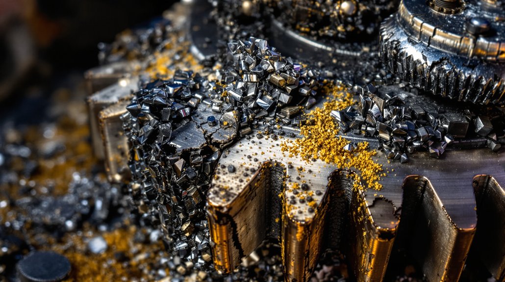
- Diagnose replacement need from excessive blow-by, abnormal oil consumption, low cylinder compression, or metal in oil filters.
- Use proper lifting gear, certified slings, and a documented lift plan with a certified attendant during hoisting.
- Follow strict LOTO: de-energize systems, verify zero energy, isolate fuel/high‑pressure oil, and record actions before work.
- Tag-match assemblies, record measurements (clearances, ring gaps, bearing clearances), and reject components outside OEM acceptance limits.
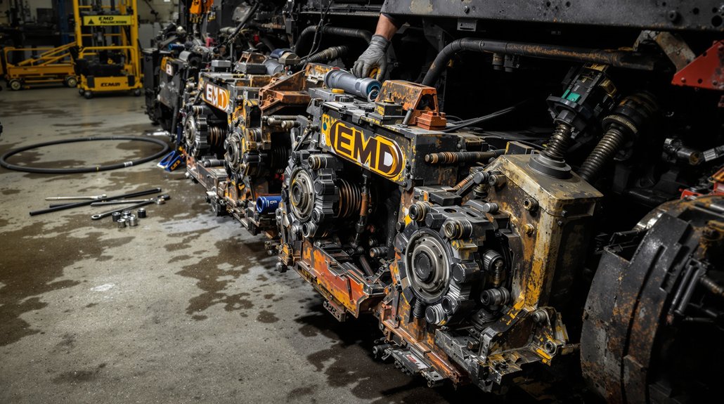
When and Why Power Assemblies Are Replaced
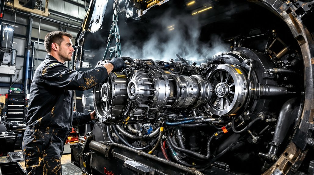
When measured piston-to-liner clearance, ring end-gap, skirt wear, or cylinder taper exceeds OEM tolerances you’ll replace the power assembly to restore compression and fuel efficiency; common triggers include excessive blow-by (well over a 95‑second benchmark), abnormal oil consumption, or persistent low compression on cylinder-specific leakage tests. You’ll schedule replacement at recommended service intervals—typically around 1,000,000 miles for EMD 710-series or every seven years under low annual mileage—documenting baseline diagnostics and failure mode evidence.
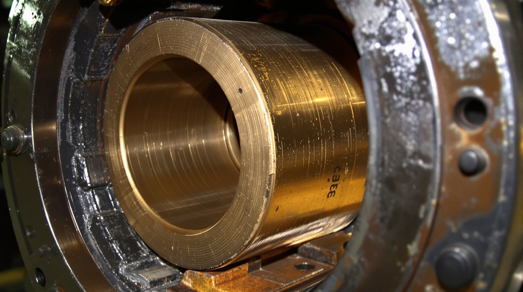
You’ll remove the cylinder head, extract the assembly, and inspect crank journals, bearings, and related hardware for collateral damage. You’ll avoid mixing incompatible family parts, fit OEM-equivalent liners, pistons, and rings, and follow torque and installation sequences precisely. You’ll perform timing, leak and break-in procedures, then update maintenance records. You’ll also consider environmental impacts: properly contain and dispose of oils, coolants, and worn components, and verify emissions and fuel-efficiency benefits post-replacement to confirm the intervention’s effectiveness.
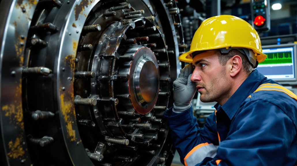
Diagnostic Signs and Failure Modes
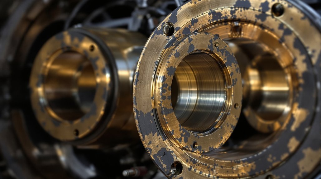
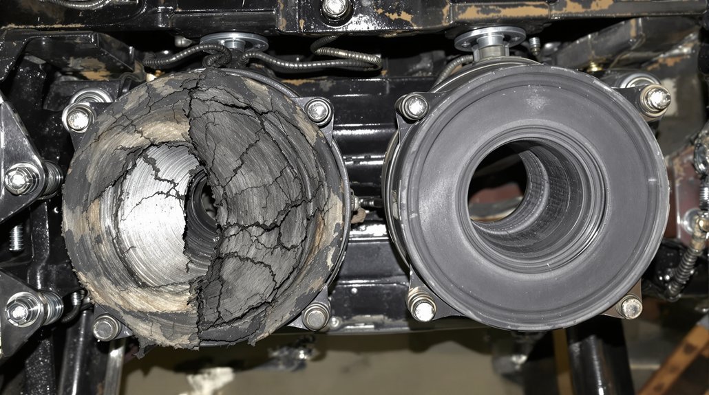
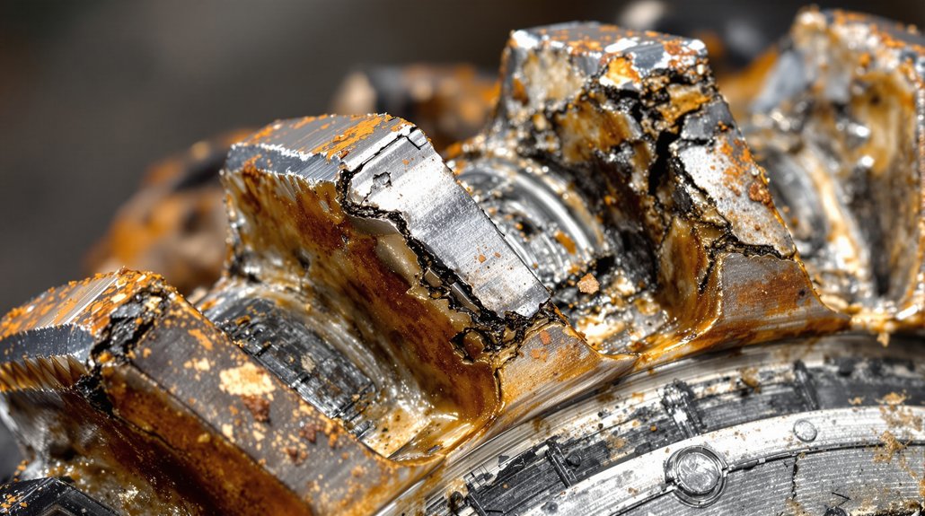
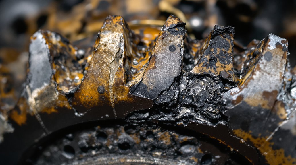
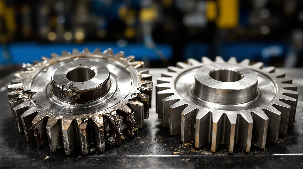
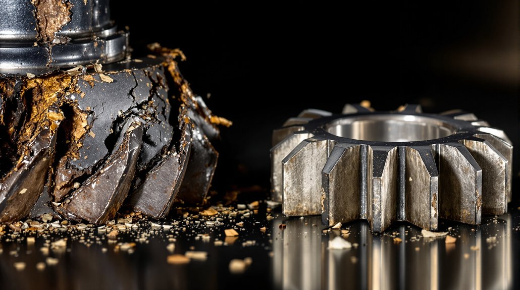
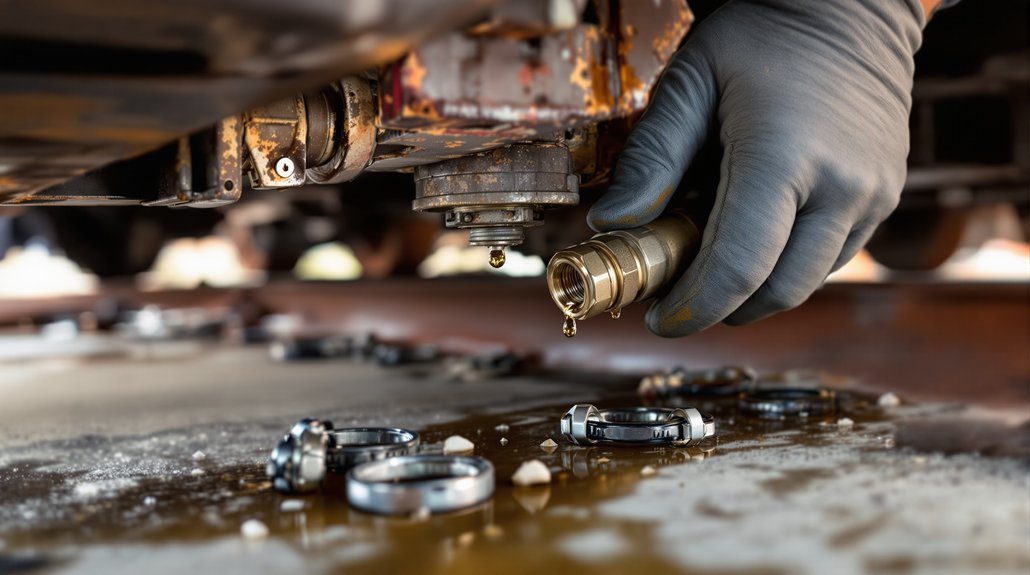
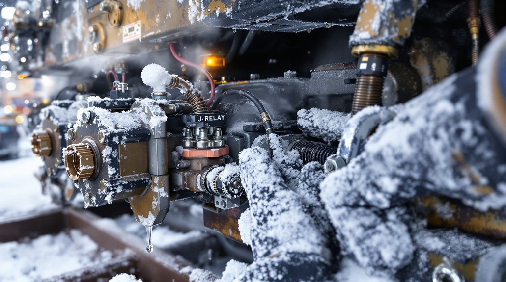
Although symptoms can overlap, you’ll usually see distinct diagnostic signs that pinpoint power-assembly failure: excessive blow-by or visible crankcase fumes indicate worn rings or scored liners, sudden oil-pressure loss with metal in filters signals bearing or rod failure, and cylinder-to-cylinder compression variance greater than 10–15% points to ring damage, cracked pistons, or head-gasket leaks; follow these checks. Measure blow-by with the EMD protocol; record values exceeding the 95-second benchmark. Inspect crankcase ventilation paths for oil carryover and contaminants.
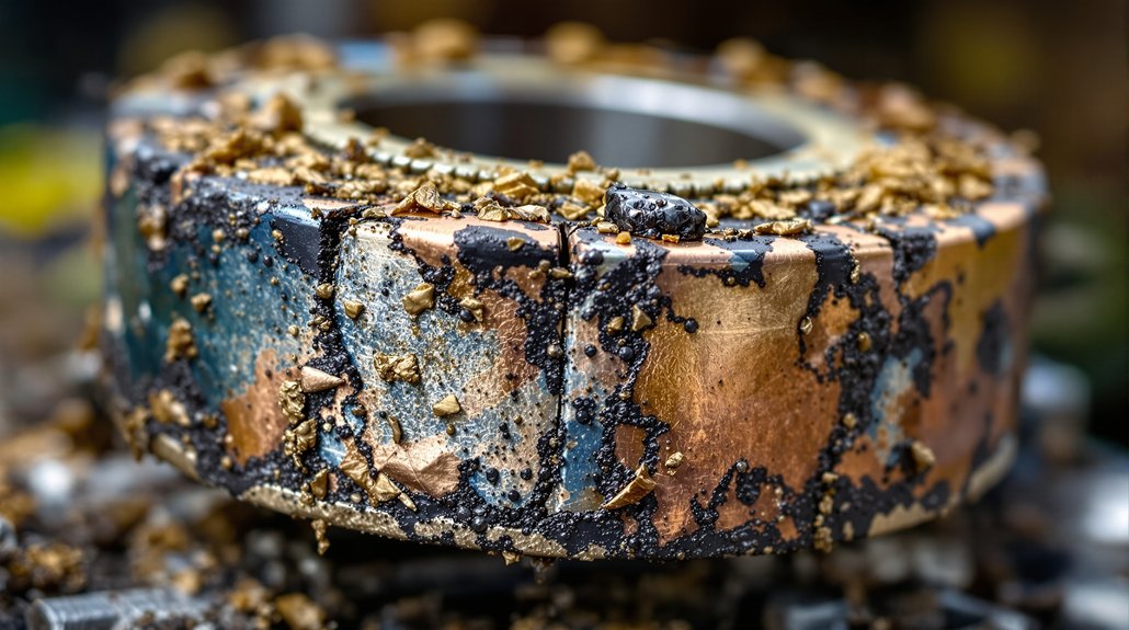
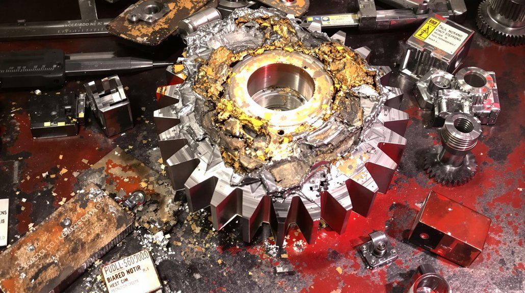
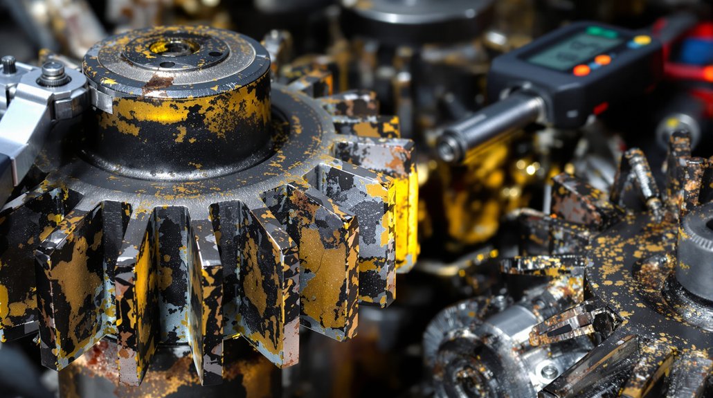
Drain and magnet-check oil, then microscopy-filter samples for ferrous particulates to confirm bearing or rod distress. Perform comparative compression and leak-down tests across all cylinders to localize sealing failures. Note smoke color and quantify oil consumption for oil-control ring or liner wear. Listen for knock/vibration under load to diagnose rod bearing or piston slap. Visually inspect removed power-assembly components for scoring, heat distress, and combustion deposits to establish failure mode and scope for replacement.
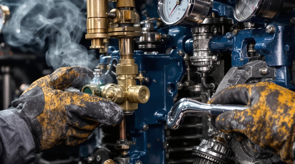
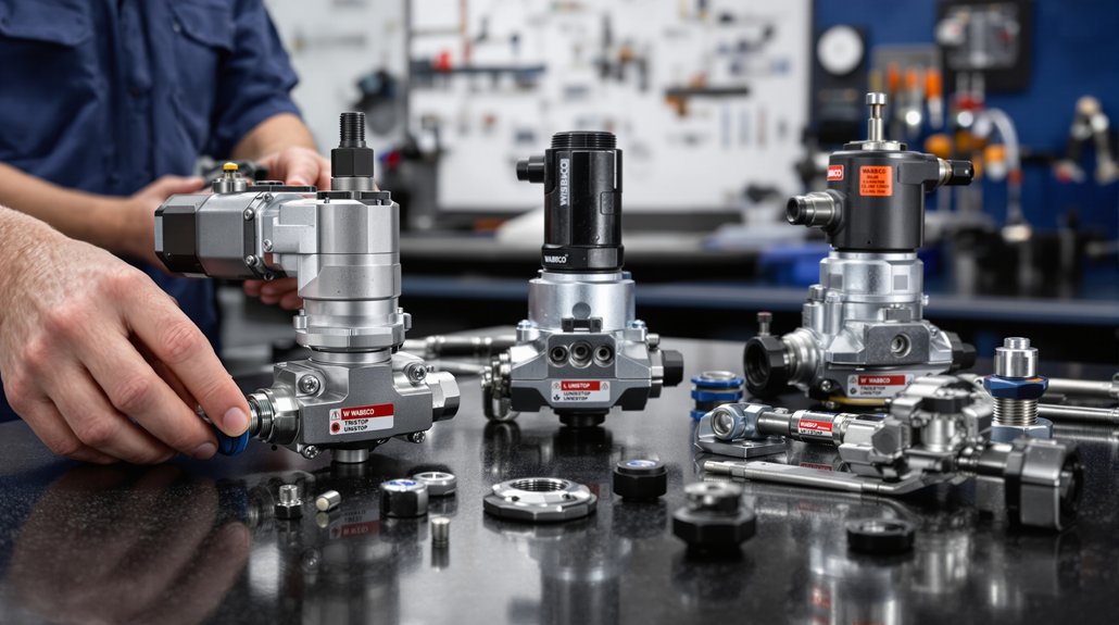
Required Tools, Equipment, and Shop Setup
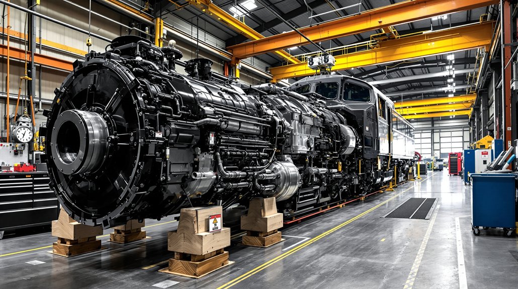
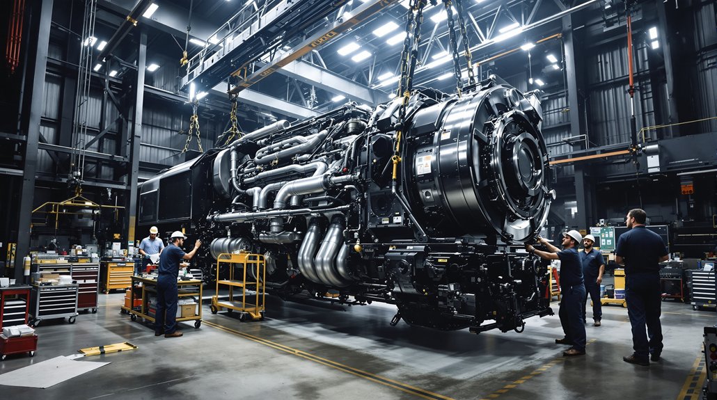
You’ll need rated lifting and rigging sized for full power assembly weights (EMD 710 assemblies ≈1,200–1,500 lb) and an overhead hoist with at least a 2:1 safety factor to move and position assemblies safely. Verify slings, shackles, and load-rated lifting points before each lift and follow documented rigging procedures to prevent shock loads and misalignment. Also prepare calibrated precision measurement tools—micrometers, bore gauges, dial indicators, and feeler gauges with current calibration certificates—to record critical dimensions before and after removal.
Lifting and Rigging
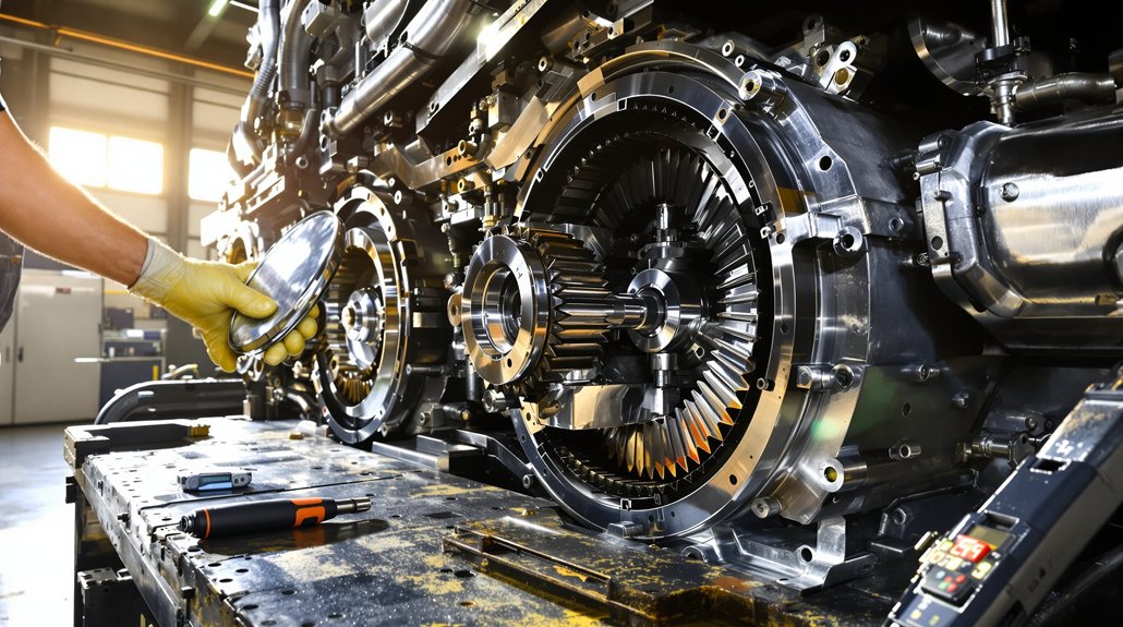
Because power assemblies weigh several hundred pounds and present serious hazards if handled improperly, you must set up lifting and rigging to exact specifications before any removal or installation. Verify crane certification and inspection tags, confirm the gantry or overhead crane is rated ≥2× maximum expected lift, and review the lift chart.
Rig with alloy steel slings or certified eyebolts at designated lift points; inspect slings for wear, elongation, and oil contamination per ANSI/ASME. Fit a properly sized spreader bar to maintain vertical alignment and prevent torsion on rods and pistons. Establish a clear, level work area with block-and-tackle backups and wheel chocks. Use precision load cells, follow a documented lift plan, and have at least two trained technicians control movement using tag line technique.
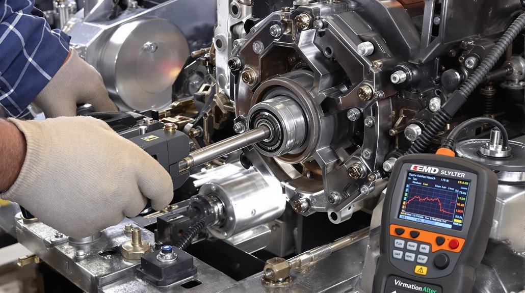
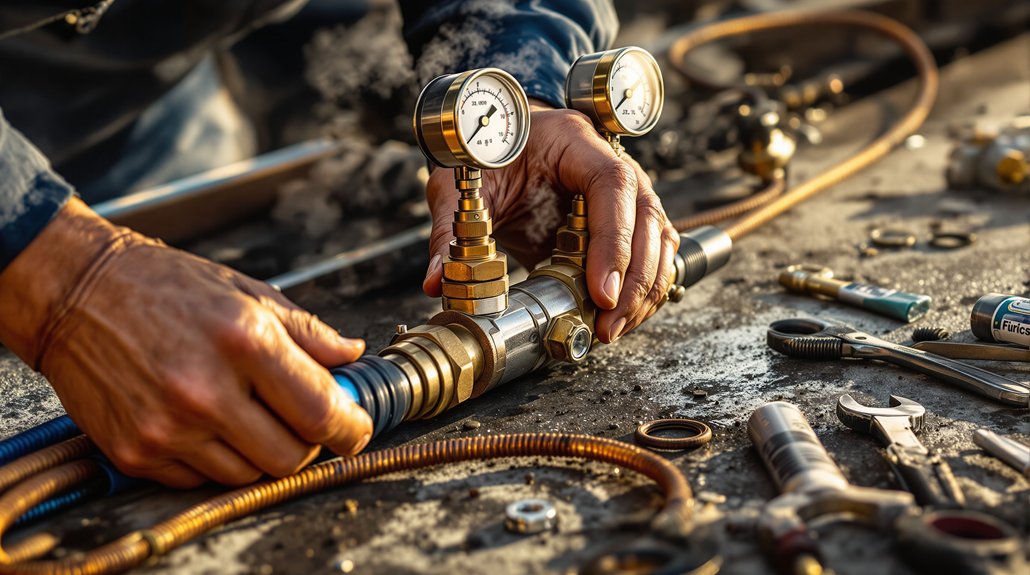
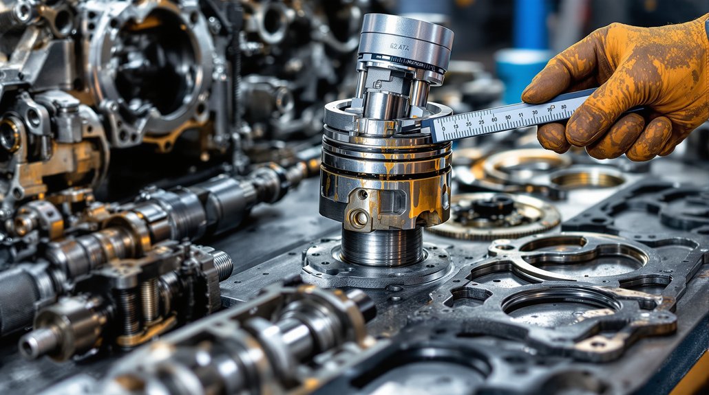
Precision Measuring Tools
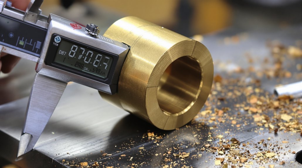
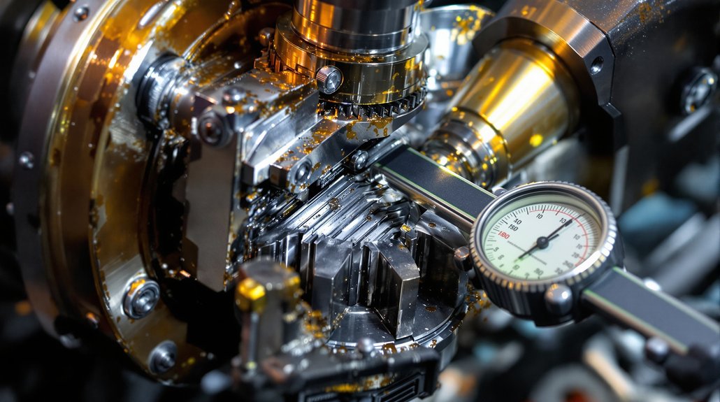
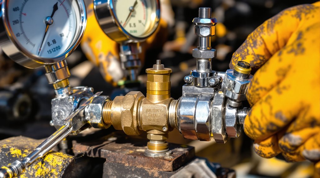
With the lifting and rigging secured, you’ll shift focus to precision measuring tools that verify component geometry and clearances before reassembly. Use a calibrated bore micrometer (4–6″ range, 0.0001″) to measure liner diameters and taper at top, middle, bottom, before and after cleaning. Verify piston-to-liner clearance with a telescoping gauge and micrometer, record readings against OEM tolerances (commonly 0.004″–0.010″). Employ a dial bore gauge for roundness and ovality, documenting deviations (typical acceptable ≤0.002″–0.005″). Use a calibrated torque wrench (0–300 ft‑lbs) and angle gauge for crab nuts and rod fasteners. Maintain a temperature‑stable bench, particle‑controlled lighting, surface plate, height gauge, fiber‑optic borescope. Consider laser interferometry for alignment and ultrasonic thickness checks for liner wall integrity.
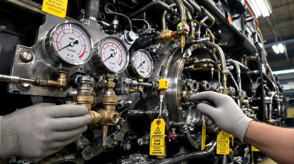
Safety Procedures and Lockout/Tagout
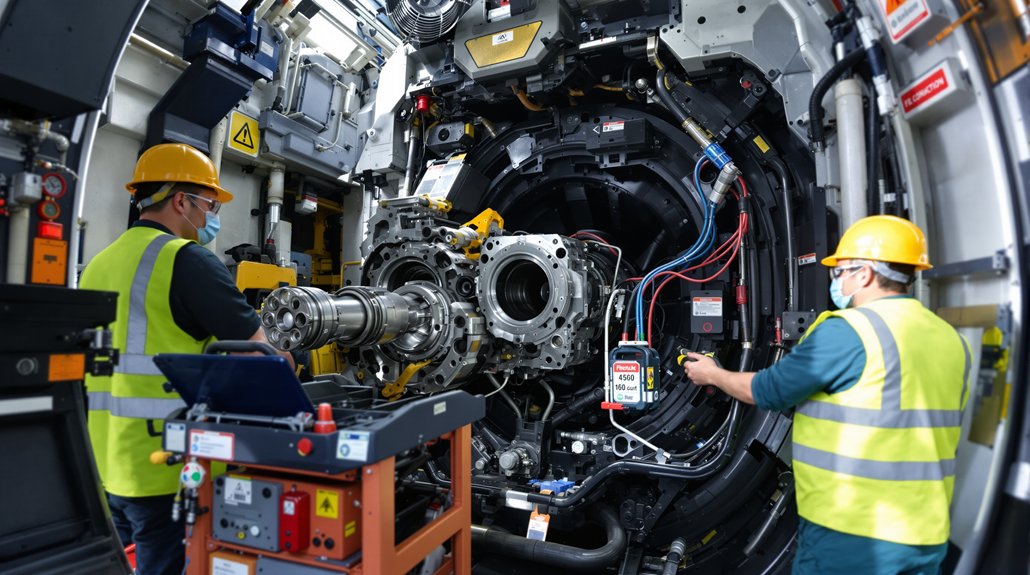
Before you remove a power assembly, de-energize the locomotive and implement a documented lockout/tagout (LOTO) procedure that isolates battery isolators, fuel shutoff, and engine start circuits using OSHA-rated padlocks and durable tags; verify zero energy by attempting a controlled start, measuring residual voltage on starter and control circuits with a calibrated multimeter, and bleeding any stored pneumatic or hydraulic pressure. Assure electrical isolation is recorded and conduct a personnel briefing that explains LOTO points, PPE, and emergency procedures.
Isolate and lock out fuel supply and high-pressure oil systems, then depressurize and cap lines; record actions on the LOTO log. Post prominent hazard tags at engine room entrance and on the control panel. Require all personnel to sign the job-specific LOTO authorization sheet before work begins. Only qualified personnel in specified PPE may remove power assemblies. Maintain a certified attendant during hoisting operations. Verify zero energy immediately before lifting and periodically while work continues. Restore energy only after inspections, clearance from the LOTO authorization holder, and documented sign-off.
Disassembly Sequence and Best Practices
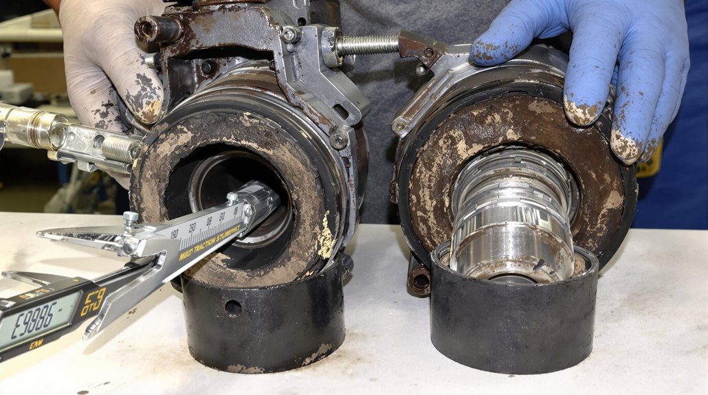
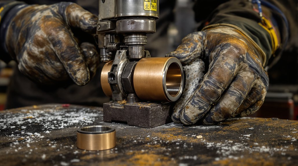
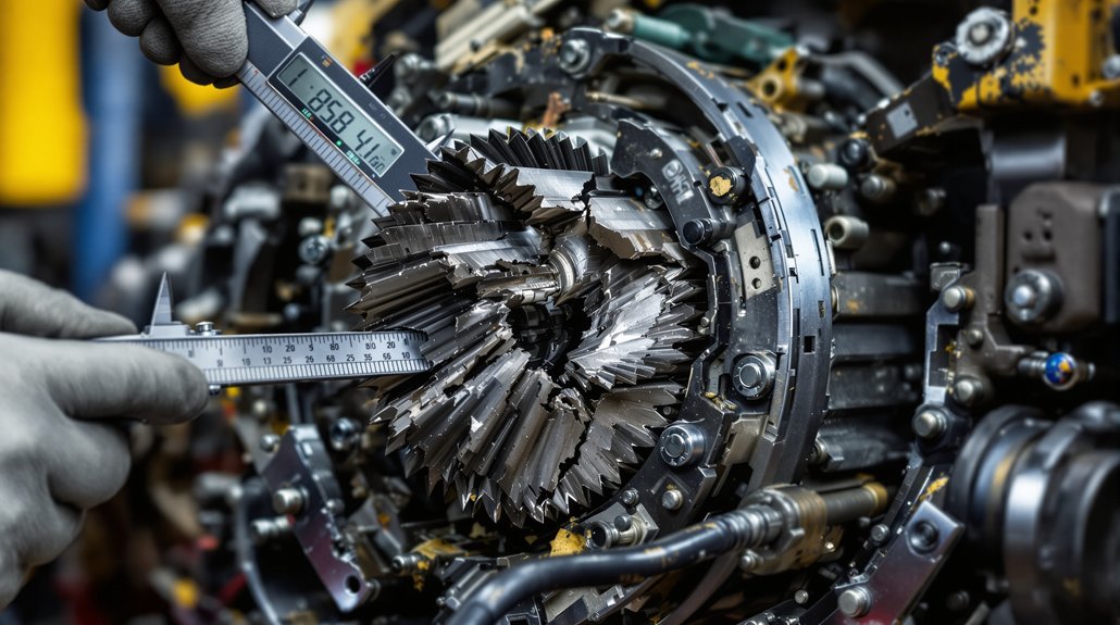
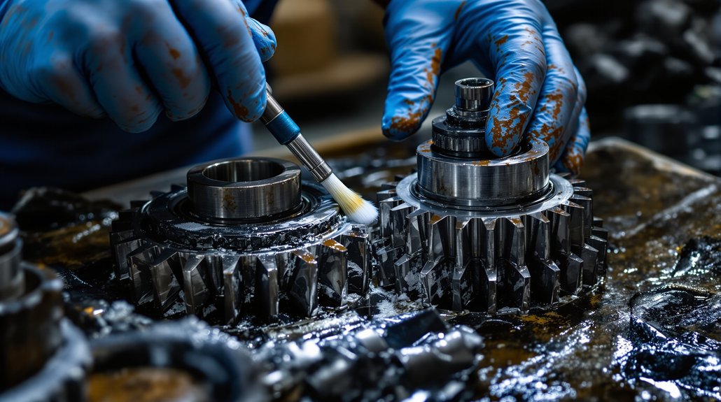
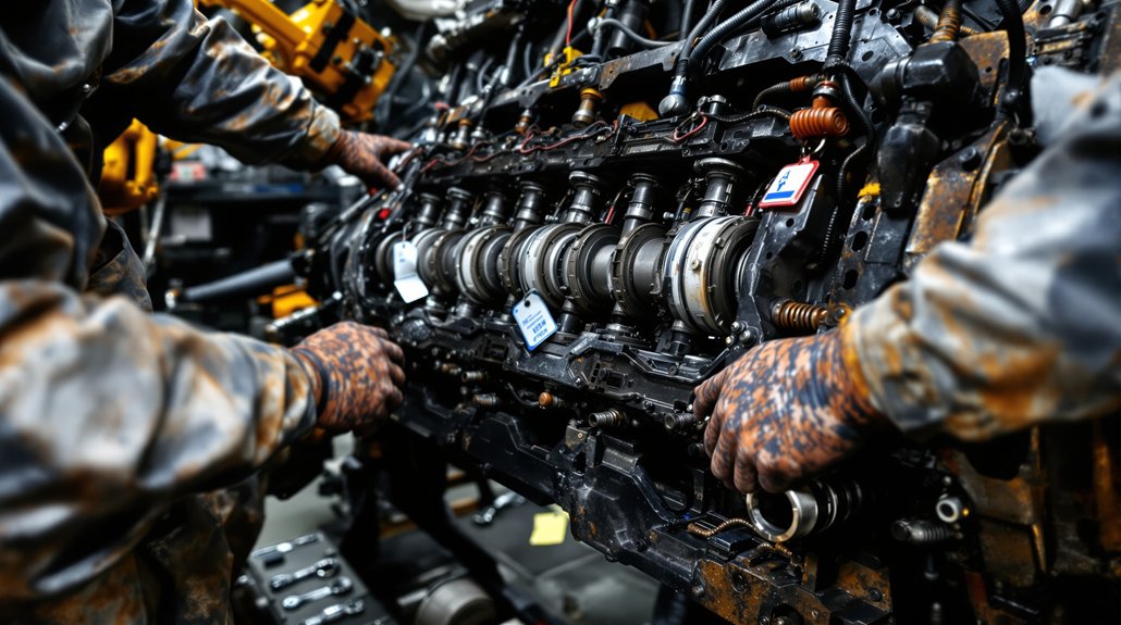
Having verified zero energy and completed LOTO documentation, begin the disassembly by recording all critical measurements (piston-to-liner clearance, ring end gaps, rod bearing clearances) and tagging each power assembly to its original cylinder to preserve match-fit relationships. Drain oil and coolant, remove ancillaries (fuel lines, injectors, rocker covers, valve gear) and follow manufacturer fastener loosening patterns—gradual, alternating—to avoid distortion.
Unbolt head and caps per sequence, mark rod and cap orientation, and bag small hardware immediately using component tagging for traceability. Support the piston/rod assembly, unbolt connecting rod caps, and use the reverse cap-splitting and ring-compressor method to push the piston up and out while keeping rings compressed to prevent damage. For liner extraction, use an engine hoist or pick tool to lift the power assembly straight up to avoid scuffing; employ a fiber-optic endoscope for a quick bore check after removal. Place components on clean, labeled benches and seal parts to prevent contamination prior to inspection.
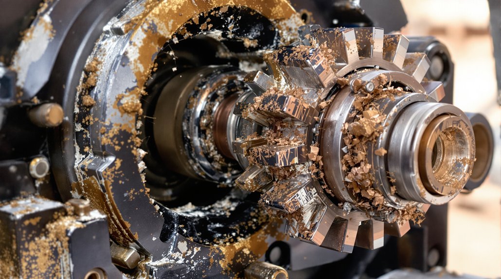
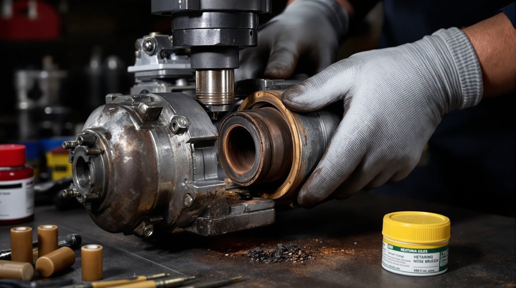
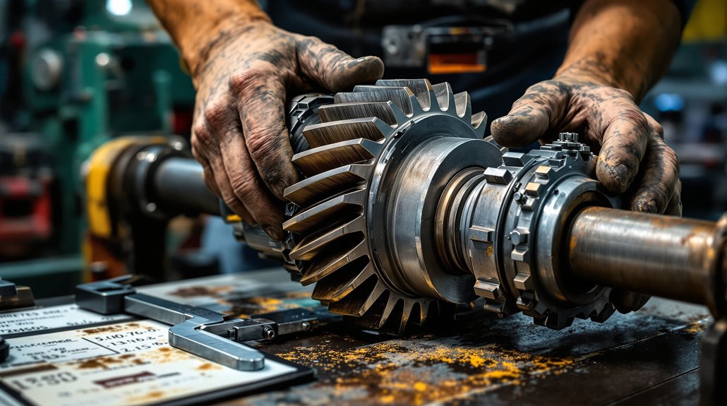
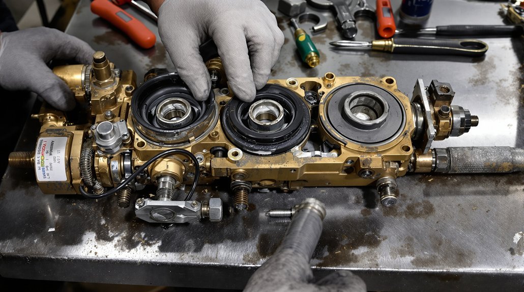
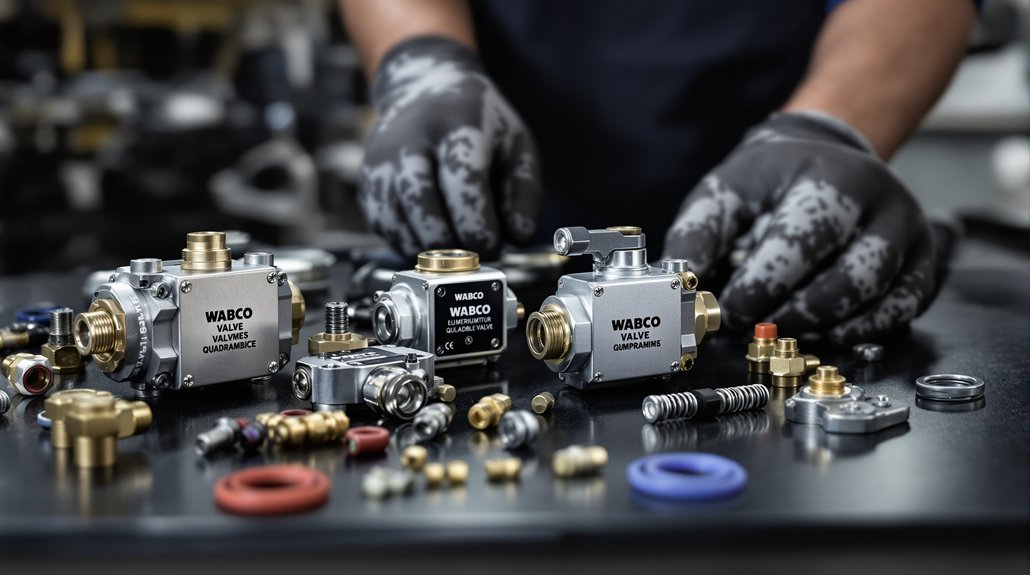
Inspection, Measurement, and Acceptance Criteria
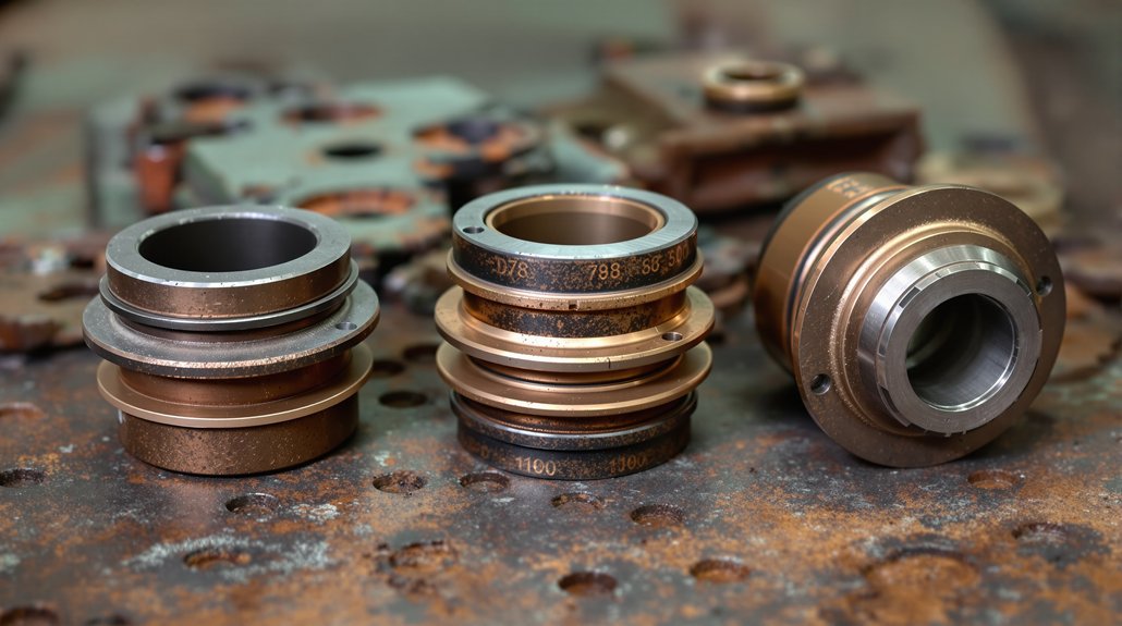
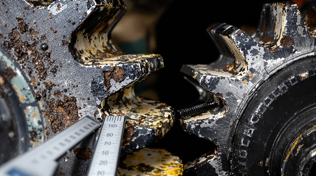
Although the disassembly provides access to components, you’ll need a systematic inspection and measurement process to determine serviceability and acceptance. Record baseline measurements (piston skirt-to-liner clearance, ring end gaps, crankpin/main journals, liner taper) and compare after cleaning or replacement. Conduct bore inspection with a bore gauge and micrometer; accept piston-to-liner clearances of 0.002–0.006 in (0.05–0.15 mm) per EMD/service spec and reject liners with taper or out-of-round beyond OEM limits.
- Measure ring seating and end gaps by placing rings in a representative liner and using feeler gauges; replace rings if end gaps exceed OEM limits or show scored faces, glazing, or broken lands.
- Use a dial indicator to check connecting rod bearing clearance and crank journal roundness; accept only if clearances match engine-specific torque/clearance charts and journals have no scoring or heat discoloration.
- Perform a blow-by/cylinder leakage test (target blow-by under 95 seconds) and verify oil/coolant passages, O-rings, and counterbores are clean and sealed before acceptance.
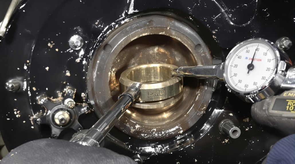
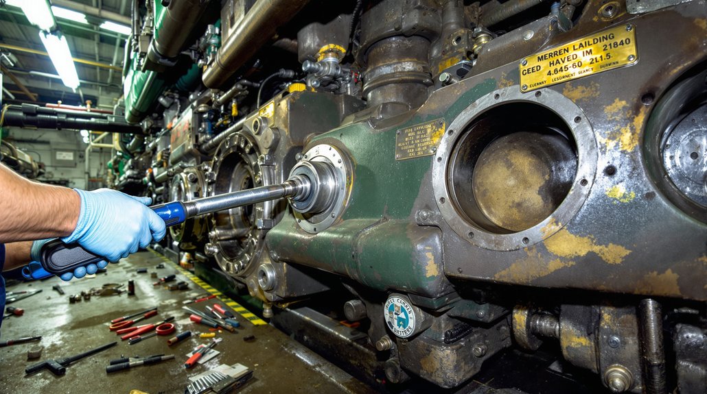
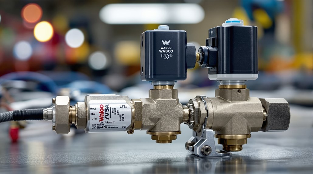
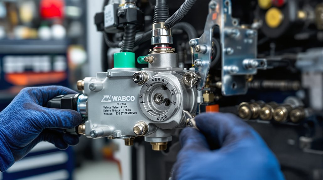
Reassembly, Torqueing, and Post-Repair Testing
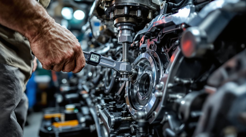
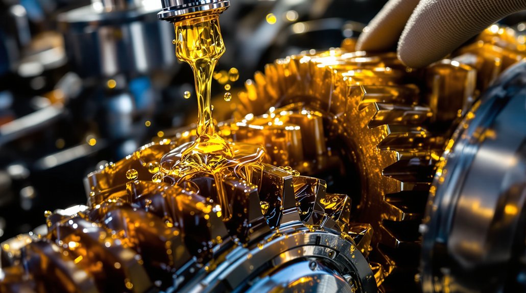
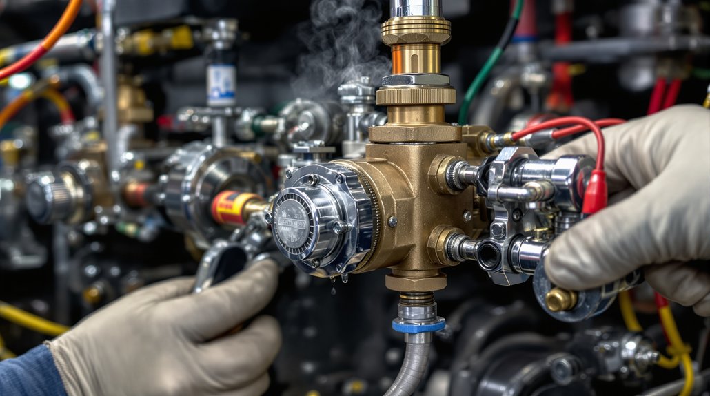
Reinstall the power assembly components methodically, following the manufacturer’s sequence and torque values to guarantee proper clamp load, alignment, and sealing. Torque crab nuts to 200 ft-lbs in the prescribed pattern to achieve uniform clamp load and liner alignment; record each value. Use ring compressors for piston insertion and confirm piston-to-liner clearance against prior measurements to prevent ring damage. Verify O-ring seating in counterbores and align air holes on the cylinder liner to prevent air-box leaks.
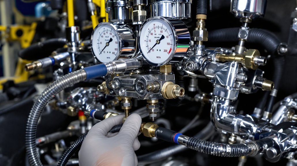
After mechanical assembly, perform precision timing and leak checks. Refill fluids, start the engine, and run controlled load testing while monitoring oil pressure, coolant temperature, vibration, and blow-by; target blow-by ≤ 95 seconds. Conduct break-in monitoring per OEM break-in cycle, rechecking torque and fluid levels after initial hours. Document torque values, clearances, and all test results in the maintenance record. If any parameter deviates, shut down, isolate the fault, and correct before returning the locomotive to service.
You may also like to read: What Causes Low Power Assembly Compression Problems in Locomotive Engines?
Frequently Asked Questions
What Is the Maintenance Checklist for a Diesel Engine?
You follow a concise maintenance checklist: inspect fuel system filters, lines, injectors; check emission controls and sensors; record piston-to-liner, ring gap, and journal measurements; change oil and filter; test oil pump pressure; clean/inspect liners, pistons, rings; torque fasteners to OEM specs; verify O‑rings and seals; perform compression and blow‑by tests; run load test monitoring temperature, vibration, and emissions; document all findings and corrective actions.
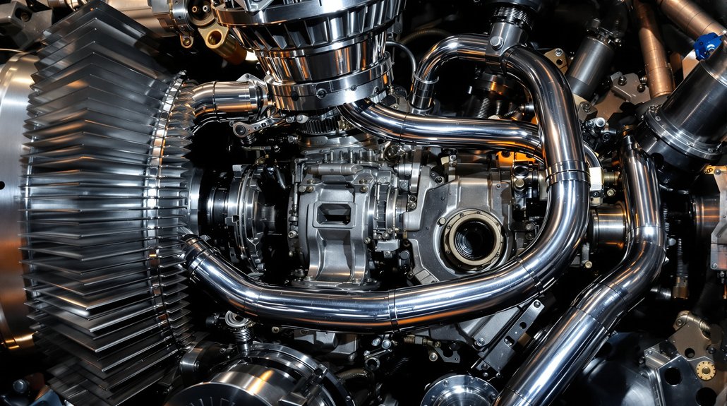
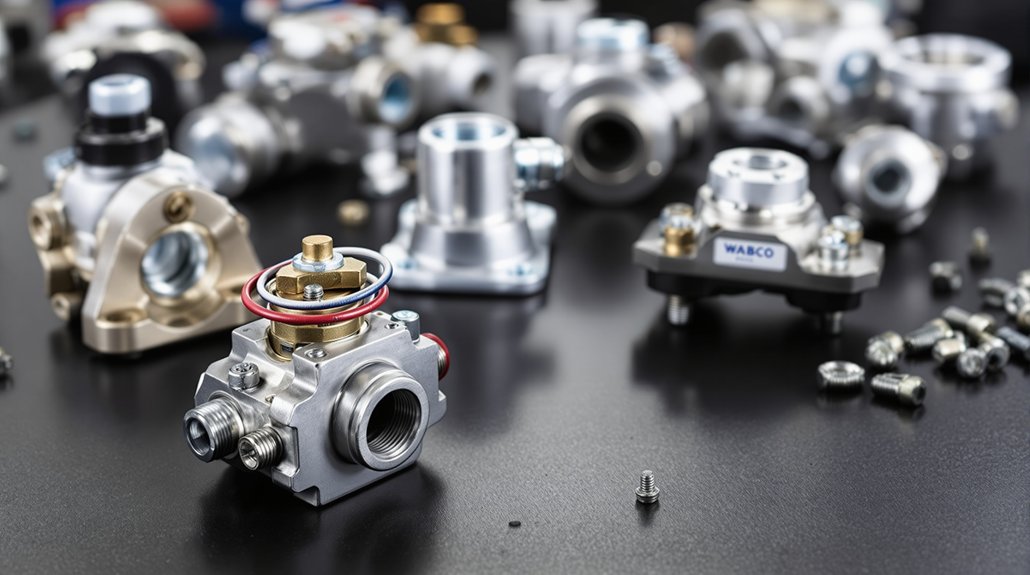
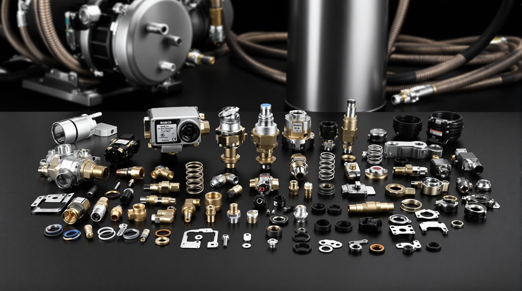
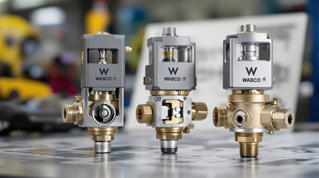
What Are the Parts of a Diesel Engine Assembly?
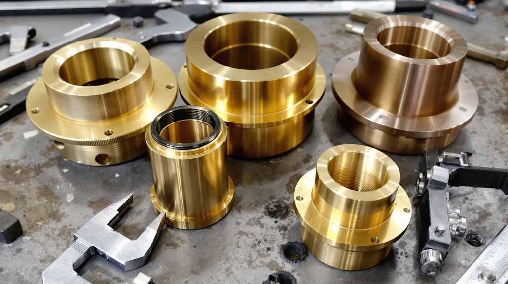
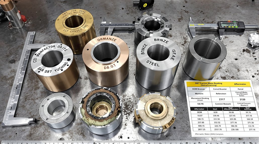
You’ll find core diesel engine assembly parts include cylinder head, piston, piston rings, cylinder liner, connecting rod with big‑end bearing, wrist pin, crankshaft, camshaft, valves and valve train, fuel pump and injectors, oil pump, cooling passages and oil galleries, gaskets and seals, fasteners (cap bolts, crab nuts), and timing gear/chain. Inspect, measure, and document each component, verify clearances to OEM specs, then install and torque per procedure to assure reliable operation.
What Is the Maintenance Schedule for a Diesel Engine?
You follow a scheduled routine: change oil and filter ~25,000 miles, service air filters every 15–30k miles, plan full power assembly rebuilds at 1,000,000 miles or 7 years, and inspect cooling system seasonally. Test compression and blow‑by during major services, monitor turbo and intake for leaks, and use fuel additives as needed for injector cleanliness and cold starts. Document measurements, torque specs, and break‑in procedures after overhauls.
What Is Major Overhauling of Diesel Engine?
Major overhauling of a diesel engine is a complete rebuild where you disassemble to the block, perform cylinder reconditioning, replace or refurbish pistons, liners, rings, rods, bearings and the crankshaft, and restore valve train components to OEM tolerances. You’ll measure clearances, machine or fit new liners, torque fasteners to spec, perform timing and leak tests, run break-in procedures, and document dimensional verifications and performance test results before returning the engine to service.