You can detect train compressed air leaks using ultrasonic acoustic imaging systems that identify leak signatures in the 30-45 kHz frequency range. These automated systems safely detect leaks from distances up to 130 meters without requiring dangerous manual inspections under moving equipment. Modern acoustic imagers with 64-128 microphones achieve 84.6% detection accuracy while eliminating worker exposure to hazardous rail environments. The technology generates real-time electronic alerts with precise leak locations and severity ratings for immediate maintenance response coordination.
Key Takeaways
- Use ultrasonic detection equipment to identify acoustic signatures between 30-45 kHz frequencies where compressed air leaks produce distinct sound patterns.
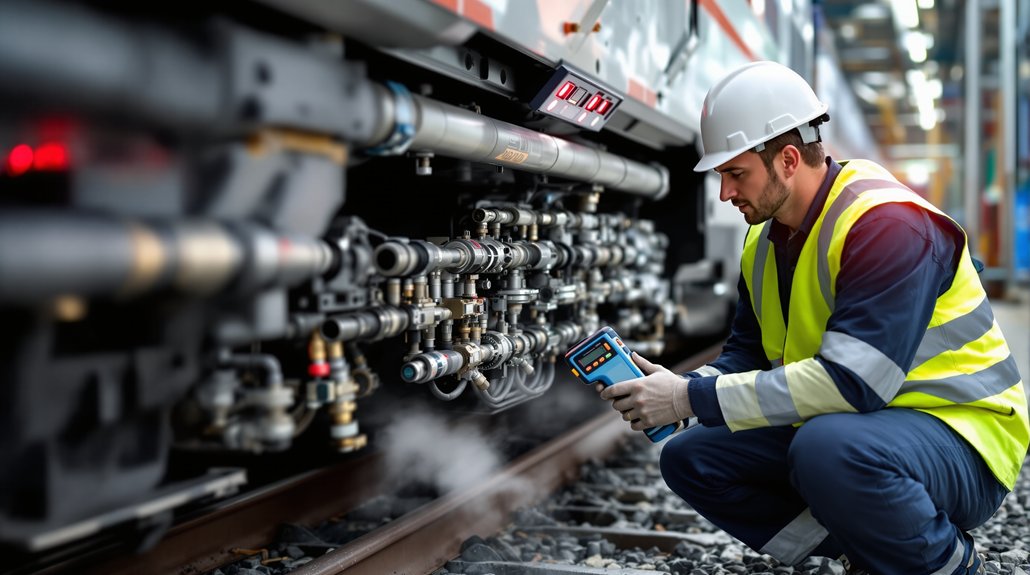
- Deploy acoustic imager technology with microphone arrays to visually locate leaks from safe distances of 5-10 feet without system shutdowns.
- Install strategic sensor networks across critical pneumatic components like brake lines, door operators, and suspension systems for continuous monitoring.
- Implement machine learning algorithms that analyze pressure and acoustic data to distinguish normal fluctuations from anomalous consumption indicating leaks.
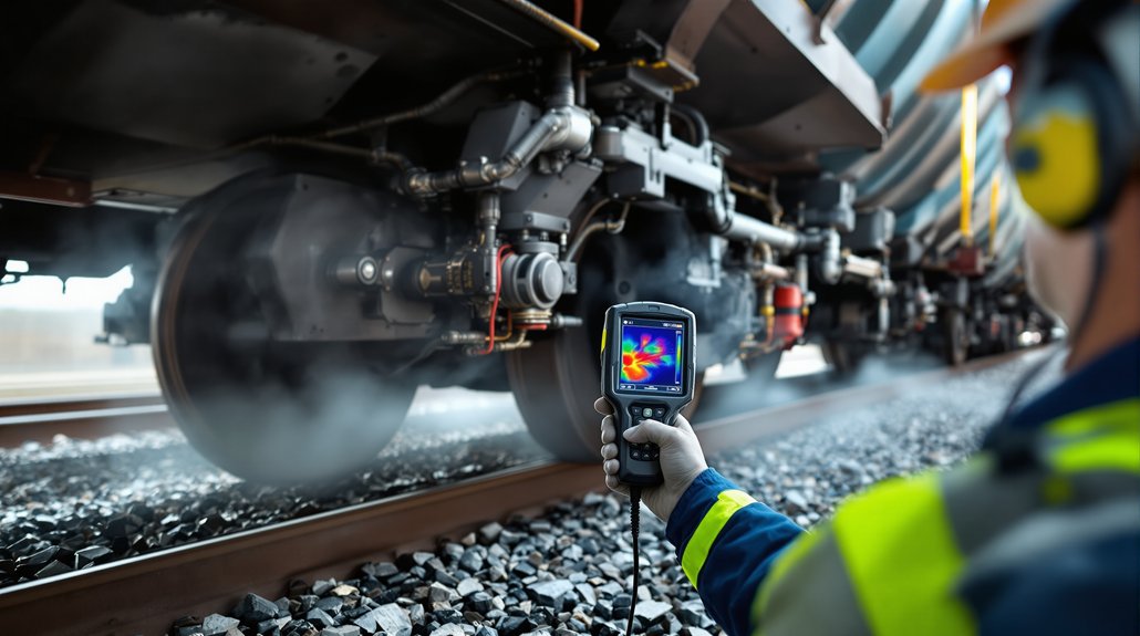
- Combine thermal imaging devices with ultrasonic sensors to detect leaks as small as 0.016 l/min while reducing inspection time by 90%.
Manual Detection Challenges in Railroad Operations
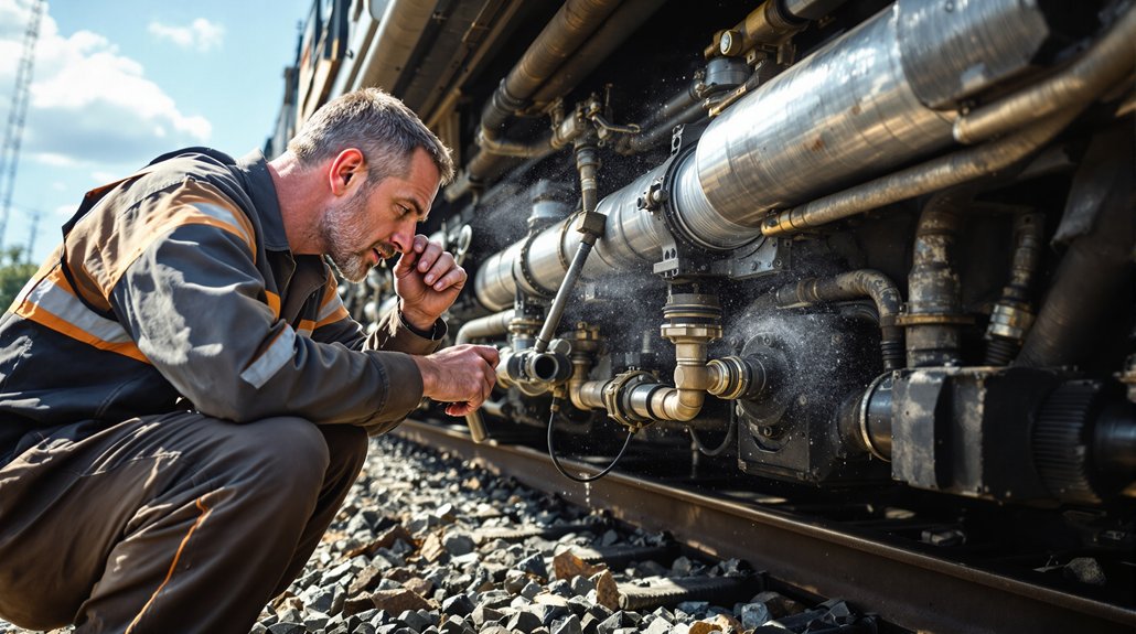
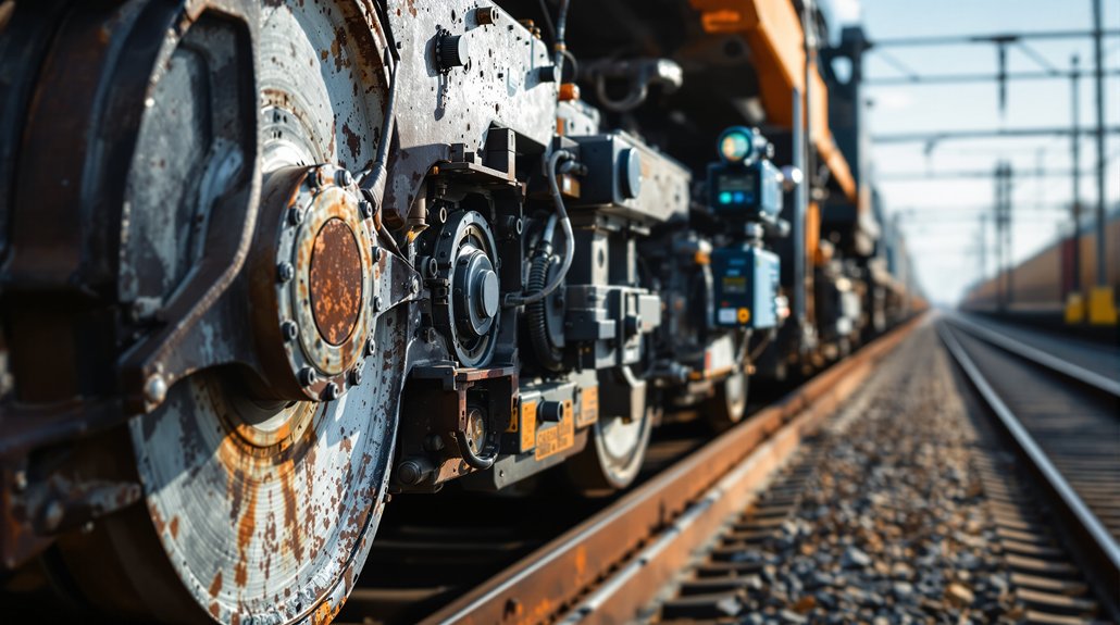
When railroad personnel manually detect compressed air leaks, they’re forced to navigate hazardous environments that expose them to significant safety risks. You’ll encounter moving train components, heavy machinery, and confined spaces around locomotives and rail cars during these inspection procedures. The physical demands of crawling under and between railway vehicles create serious inspection ergonomics challenges that can compromise both safety and detection accuracy.
Traditional detection methods require you to listen for compressed air escape sounds or feel for leaks while positioned in potentially dangerous locations. These time-intensive processes can take hours or days, leading to worker fatigue that further increases safety risks. Your detection accuracy depends heavily on experience and hearing ability, while background noise from train operations often masks smaller leaks. Weather conditions and environmental factors additionally impair your effectiveness, making manual detection both unreliable and hazardous for maintenance personnel. The rail industry loses an estimated 2–3% vehicle efficiency annually due to these undetected air leaks.
Automated Audio Detection Technology Solutions
You’ll find that modern automated audio detection systems leverage sophisticated acoustic imager technology to identify compressed air leaks without requiring manual inspections. These systems integrate machine learning algorithms that analyze frequency signatures between 30-45 kHz, where compressed air leaks produce distinct acoustic patterns separable from background railway noise. Your detection capabilities improve markedly through this technology, achieving detection rates of 11 out of 13 leaks with false positive rates as low as 0.03% during operational testing. The technology addresses significant efficiency losses in the rail industry, where compressed air leaks typically reduce vehicle efficiency by 2% to 3%.
Acoustic Imager Technology
Acoustic imaging technology transforms compressed air leak detection by combining ultrasonic sensors with visual cameras to pinpoint leaks in real-time. You’ll achieve precise acoustic mapping through advanced sensor calibration that eliminates background noise interference common in railway environments.
| Equipment Model | Sensor Count | Detection Range |
|---|---|---|
| FLIR Si124 | 124 microphones | Up to 120 meters |
| CRYSOUND | 128 MEMS sensors | Extended distance |
| Standard Units | 64-96 sensors | 50-80 meters |
| Compact Models | 32-48 sensors | 25-40 meters |
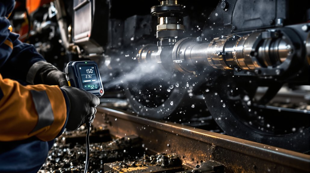
The technology detects leaks as small as 0.016 l/min while overlaying ultrasonic data onto visual images. You’ll reduce inspection time by 90% compared to traditional methods. Equipment operates safely from distances without requiring system shutdowns, making it ideal for continuous railway operations where safety protocols demand non-invasive detection methods. This visual ultrasound approach transforms sound into visual data, enabling inspectors to identify compressed air system inefficiencies that would otherwise remain hidden during routine maintenance checks.
Machine Learning Integration
While traditional acoustic detection relies on manual interpretation, machine learning algorithms now automate compressed air leak identification by processing ultrasonic frequency data in the 30-45kHz range where leaks produce distinct signatures above background railway noise. You’ll train these AI systems using hydrophone recordings with verified leak and non-leak examples, incorporating variables like gun volume, pressure, and depth configurations. The algorithms process incoherent signal distortions that classical methods can’t define effectively.
Your implementation requires robust data governance protocols to guarantee training dataset quality and regulatory compliance. Model explainability becomes critical when justifying maintenance decisions to stakeholders. You’ll integrate these systems with existing flow sensors and control infrastructure, generating real-time electronic alerts with visual documentation. This approach enables continuous monitoring without operational shutdowns while providing predictive maintenance capabilities through IoT connectivity. Advanced systems utilizing 64-microphone arrays can achieve detection rates of 11 out of every 13 leaks on moving trains.
Detection Performance Metrics
Machine learning algorithms require quantifiable performance benchmarks to validate their effectiveness in operational railway environments. You’ll achieve 84.6% accuracy rates when detecting compressed air leaks on moving trains, maintaining false positive rates at just 0.03% during field operations. Your system will identify approximately 11 out of every 13 leaks during moving evaluations, with performance improving through additional data collection.
Proper sensor calibration guarantees detection from 2.5 meters for small leaks up to 130 meters for larger ones. Environmental effects don’t compromise your ability to detect minimum leak sizes of 0.01 liters per minute. You’ll receive confidence ratings for each identified leak location, enabling maintenance personnel to prioritize repairs effectively. Field testing demonstrates successful detection across 30-40 leaks within operational timeframes. The acoustic sensor operates within 30-45 kHz frequencies where compressed air leak signatures are most distinguishable from background noise.
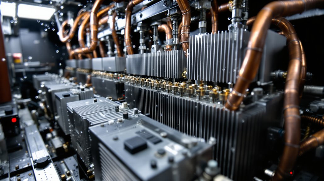
Acoustic Imaging Equipment and Frequency Analysis
Transform sound waves into precise visual data using acoustic imaging cameras that detect ultrasonic frequencies generated by compressed air leaks on railway equipment. These specialized cameras utilize MEMS arrays containing multiple microphones to capture high-frequency acoustic signals that turbulent air creates when escaping from pneumatic systems.
You’ll achieve peak detection by operating within the ultrasonic bandwidth range where compressed air leaks generate their strongest acoustic signatures. The carefully constructed MEMS arrays provide high sensitivity imaging that overlays ultrasonic information onto visual camera feeds in real time.
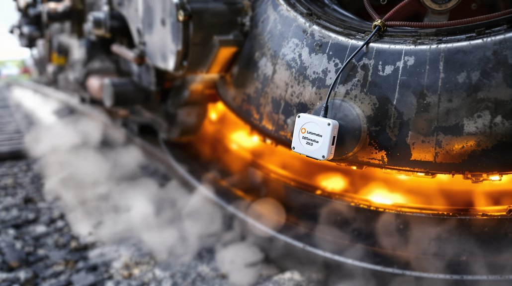
Advanced models like the FLIR Si2-LD enable detection from distances up to 130 meters, ensuring safe inspection of energized train systems. The equipment’s noise suppression technology filters background industrial sounds, allowing you to identify leak sources precisely even in noisy rail yards. This acoustic imaging approach reduces inspection time by approximately 90 percent compared to traditional ultrasonic detection methods. Modern acoustic cameras feature onboard analytics that automatically calculate financial losses from each detected leak, enabling immediate cost-benefit analysis for repair prioritization.
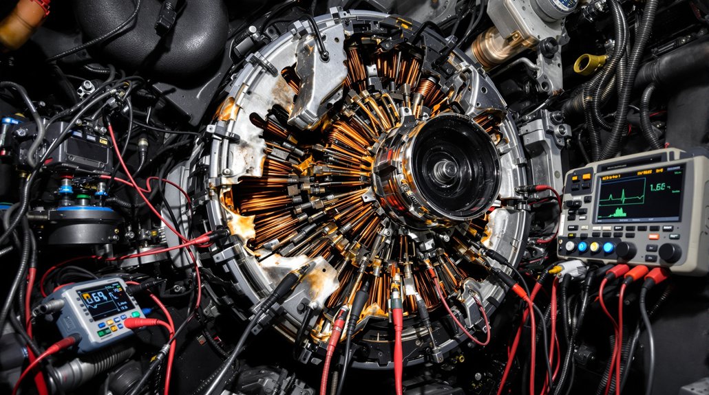
Multi-Sensor Integration With Machine Learning
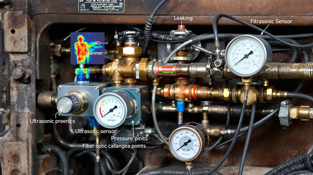
Acoustic imaging cameras provide powerful standalone detection capabilities, yet combining multiple sensor technologies with machine learning algorithms creates complete leak detection systems that surpass single-sensor performance. You’ll achieve peak results by integrating ultrasonic sensors, pressure transducers, and thermal imaging devices through strategic sensor placement across critical pneumatic components.
Machine learning algorithms process multi-sensor data streams to identify leak patterns that individual sensors might miss. You can implement data augmentation techniques to expand training datasets, improving algorithm accuracy for detecting subtle pressure variations and acoustic signatures specific to railway compressed air systems.
Smart sensor networks enable real-time monitoring of brake lines, door operators, and suspension systems simultaneously. You’ll benefit from automated alert systems that distinguish between normal operational sounds and actual leaks. Advanced algorithms learn your specific train fleet’s acoustic fingerprints, reducing false positives while ensuring critical safety systems maintain proper pressure levels for reliable braking and door operation.
Establishing a compressed air baseline through thermal mass flowmeters enables precise measurement of your system’s consumption patterns before implementing leak detection protocols. Machine learning models use this baseline data to distinguish between normal operational fluctuations and anomalous consumption indicating potential leaks throughout the pneumatic network.
Performance Metrics and Detection Accuracy Rates
When evaluating compressed air leak detection systems for railway applications, you’ll find that current automated technologies achieve an 84.6% overall accuracy rate in identifying leaks on moving trains. These systems successfully identify 11 out of every 13 leaks during operational testing, ensuring regulatory compliance with safety standards while reducing environmental impact through energy conservation.
You can expect detection capabilities ranging from 0.01 liters per minute for small leaks at close range to extensive scanning at distances up to 130 meters. The false positive rate remains exceptionally low at 0.03%, which prevents unnecessary maintenance interventions and maintains operational efficiency. Modern handheld systems utilize 96 ultra-sensitive microphones to capture ultrasonic sound waves that indicate air leaks in railway brake systems.
Machine learning algorithms demonstrate consistent performance in distinguishing actual leaks from background noise across 2 to 100 kHz frequency ranges. Your maintenance teams can identify and repair 30 to 40 leaks within hours using these systems, markedly improving both safety protocols and environmental stewardship through reduced compressed air waste.
Alert Systems for Maintenance Personnel
Modern compressed air leak detection systems automatically generate and transmit electronic alerts to your maintenance personnel the moment they identify leaks on moving trains. These automated notifications eliminate dangerous manual inspection procedures while providing precise location coordinates and severity assessments through real time dashboards and mobile alerts.
Your alert system delivers thorough data packages containing:
- Total leak count per inspection cycle with confidence levels
- Precise coordinates and positioning data for each detected leak
- Visual documentation from integrated cameras highlighting specific leak locations
- Technical specifications including severity ratings and detection frequency ranges
You’ll receive instantaneous notifications through digital communication channels, enabling immediate response coordination without stopping trains. The system integrates seamlessly with existing maintenance workflows, allowing proactive scheduling and targeted interventions. Mobile alerts ensure your personnel can assess situations remotely before on-site inspection, reducing labor requirements and minimizing exposure to hazardous environments while maximizing maintenance efficiency. These autonomous detection systems also contribute to reduced fuel consumption by identifying air leaks that would otherwise force locomotives to work harder to maintain proper air pressure levels.
Field Testing Results and System Validation
Through rigorous field testing protocols, the compressed air leak detection system achieved an 84.6% accuracy rate while maintaining exceptional reliability with false positives occurring in only 0.03% of test scenarios. You’ll find the system successfully identifies 11 out of every 13 leaks during moving train operations, demonstrating operational readiness for regulatory compliance requirements.
The multi-sensor integration combines thermal, acoustic, and visual spectrum imaging with Fluke SV600‘s 64-microphone array detecting frequencies between 30-45kHz. You can detect leaks as small as 0.01 litres per minute from 2.5 meters distance, ensuring all-encompassing coverage across locomotive locations.
Machine learning algorithms filter background noise interference while maintaining detection accuracy during dynamic train operations at various speeds. The system’s long term durability has been validated through extensive environmental condition testing, confirming performance consistency across multiple operational scenarios and supporting deployment readiness for rail yard environments. Detection systems should target maintaining leakage below 10% of total compressed air production to optimize energy efficiency and operational costs.
Implementation Benefits for Rail Yard Efficiency

You’ll experience significant operational improvements when implementing automated compressed air leak detection systems in your rail yard operations. Your maintenance teams won’t need to conduct time-consuming manual searches that require dangerous positioning on, under, or between railway vehicles, reducing both labor costs and safety risks. You can respond faster to system issues since real-time detection identifies problems immediately, allowing your crews to address small leaks before they escalate into costly major repairs.
Reduced Labor Requirements
While traditional compressed air leak detection demands significant manual labor from your mechanical staff, automated ultrasonic systems dramatically reduce these workforce requirements by eliminating the need for physical inspections. Your staff reduction becomes immediately apparent when considering that manual detection requires employees to physically search locomotives by going on, under, or between railway vehicles. Workflow optimization occurs through automated detection on moving trains without human intervention.
Key labor reduction benefits include:
- Minimal Training Requirements – Only 2 hours needed for ultrasonic detection proficiency
- Automated Notifications – Direct alerts to mechanical personnel eliminate manual searching
- Remote Detection Capability – 5-10 foot range eliminates close proximity requirements
- High Detection Accuracy – 11 out of 13 leaks detected automatically without staff investigation
Faster Maintenance Response
Automated ultrasonic detection systems accelerate your maintenance response times by delivering real-time leak alerts directly to mechanical personnel the moment compressed air leaks occur on moving trains. You’ll receive electronic notifications containing exact leak locations, system confidence levels, and accompanying images that eliminate time-consuming search procedures. This immediate data transmission enables faster dispatch of repair crews to specific problem areas rather than conducting broad inspections across entire systems.
The digital alert system supports priority routing by categorizing leak severity levels, allowing you to allocate resources efficiently based on operational impact. Your maintenance teams can coordinate responses immediately between detection and repair operations, preventing minor leaks from escalating into major system failures that require extended downtime and costly emergency repairs.
You may also like to read – How to Fix Locomotive Air System Gasket Problems
Frequently Asked Questions
What Is the Typical Cost to Install an Automated Air Leak Detection System?
You’ll face installation costs ranging from $2,000-$15,000 for automated air leak detection systems, depending on complexity and integration requirements. Basic semi-automatic platforms start around $2,000, while fully automated systems with custom fixtures, sensors, and control interfaces reach $15,000+. Factor in ongoing subscriptions for software updates, calibration services, and technical support that typically add 10-15% annually to your initial investment for optimal safety performance.
How Long Does It Take to Train Personnel on the New Detection Equipment?
Like mastering a new instrument, you’ll need dedicated practice time to become proficient. Training duration depends on your chosen format—hands on workshops typically require one to two days for thorough equipment mastery, while virtual modules can be completed in six hours for basic competency. Advanced detection systems demand prerequisite training plus hands-on experience. You’ll achieve certification once you pass the 80% assessment threshold.
Can the System Work Effectively in Extreme Weather Conditions Like Snow or Rain?
You’ll need weatherized components for reliable operation in extreme conditions. Cold weather affects seals, requiring low-temperature materials that won’t crack or harden. Install drain heaters to prevent moisture freeze-up in detection lines and instrument housings. You must verify all sensors maintain calibration accuracy below freezing and make certain protective enclosures meet IP ratings for rain penetration. Regular winter maintenance protocols become critical for consistent leak detection performance.
What Maintenance Schedule Is Required to Keep the Acoustic Sensors Properly Calibrated?
Like a finely tuned orchestra requiring regular conductor guidance, you’ll need monthly functional tests, quarterly verification checks, and annual full-system calibrations. You must perform weekly operational checks and daily visual inspections. Temperature compensation occurs every six months, while vibration baselines need monthly updates. Your sensor recalibration intervals depend on environmental exposure severity. Make certain your technician certifications renewal stays current, as proper calibration requires certified personnel following ISO standards for measurement accuracy.
How Does Detection Accuracy Compare Between Stationary Trains Versus Moving Trains?
You’ll achieve higher stationary accuracy rates compared to moving train detection due to controlled environmental conditions. Moving variability introduces background noise, vibrations, and positioning challenges that reduce the current 84.6% accuracy rate. When you inspect stationary trains, you’ll eliminate motion-related interference, allowing closer sensor positioning and more precise leak identification. You’ll experience fewer false readings and improved component-by-component examination capabilities during static inspections.