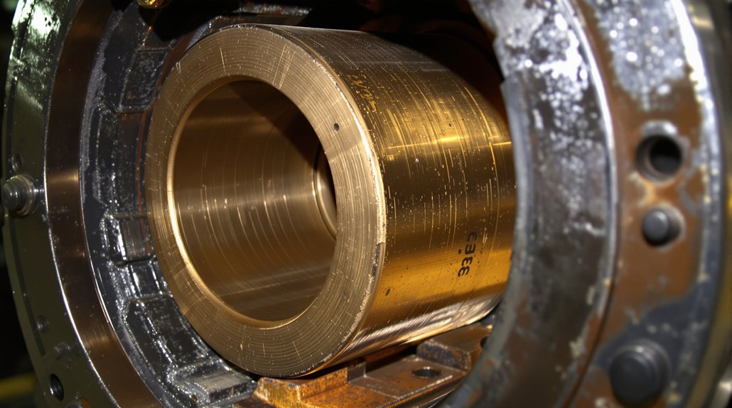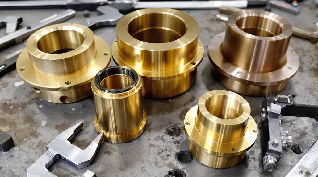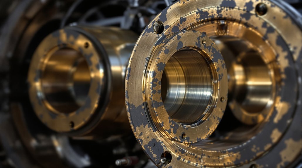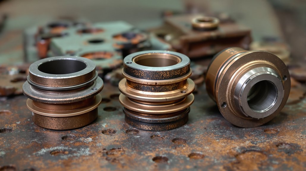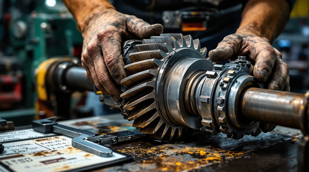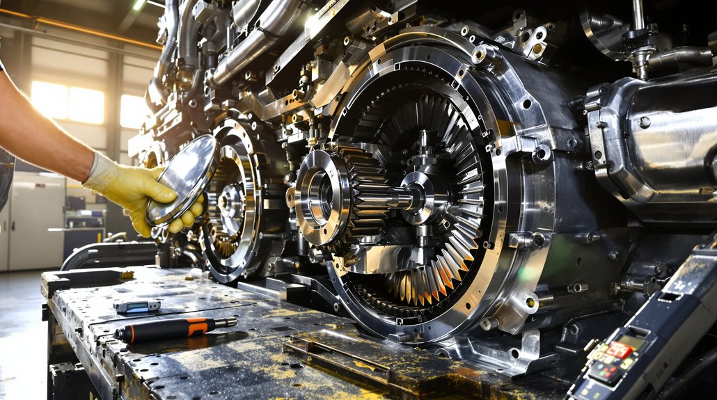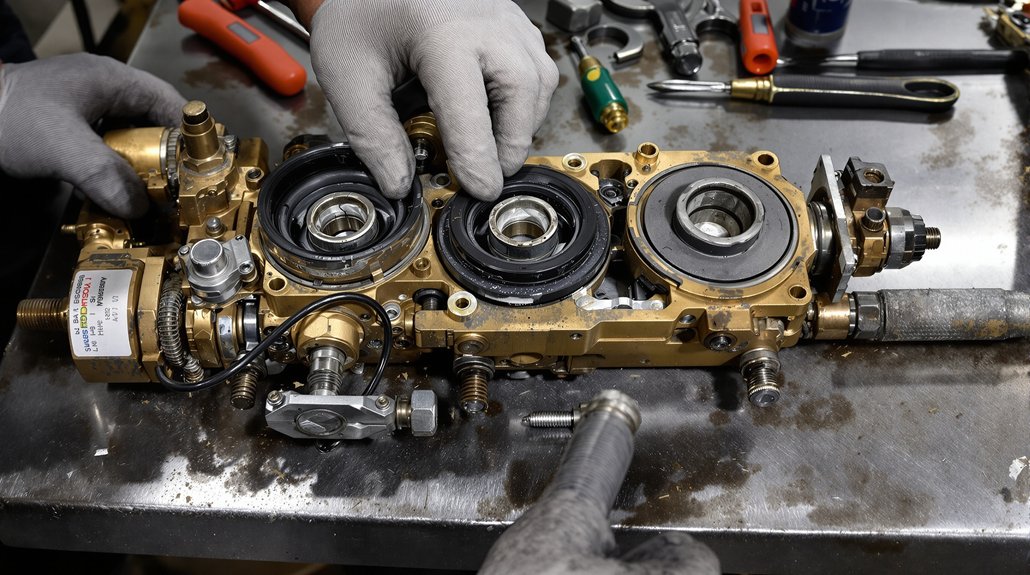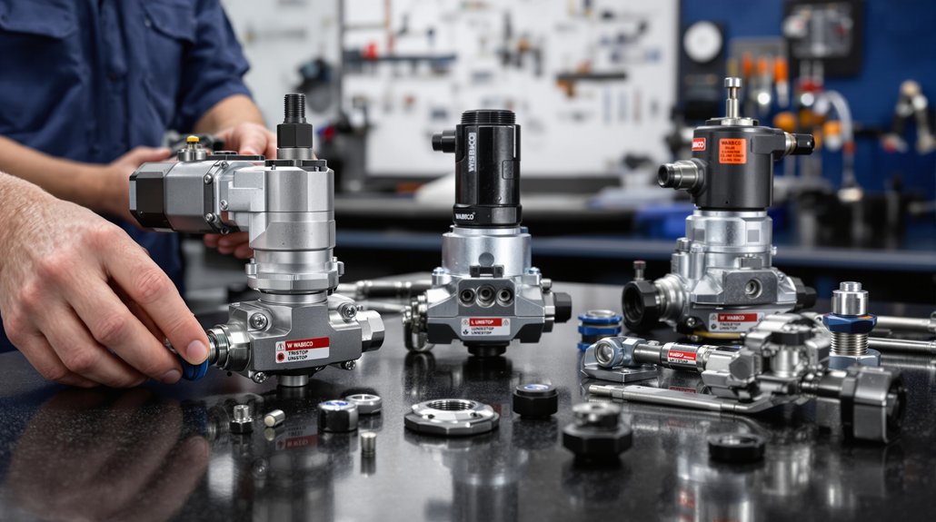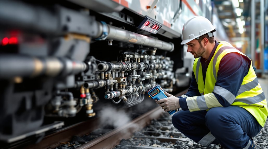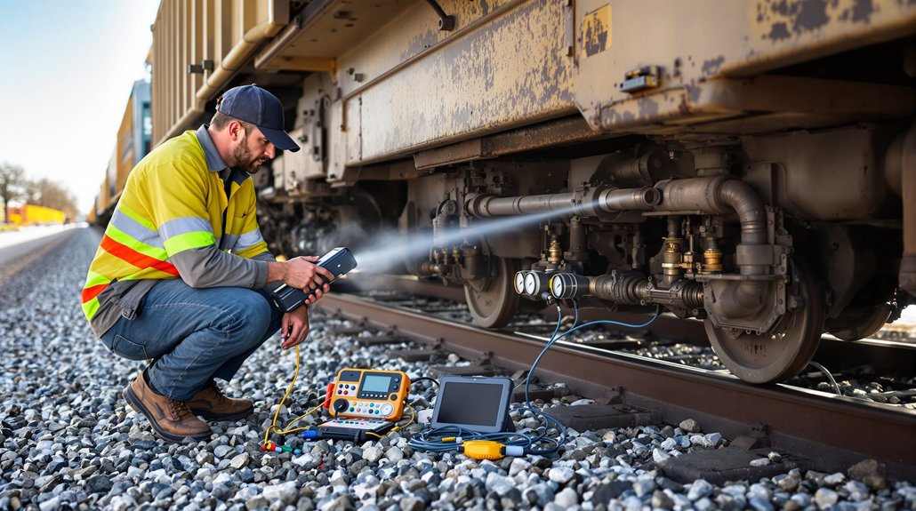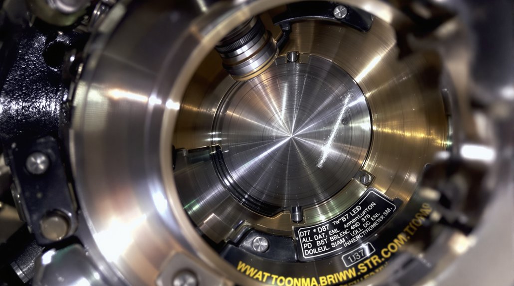
EMD Diesel Camshaft Bearing Replacement Specs Guide

EMD Diesel Camshaft Bearing Replacement Specs Guide

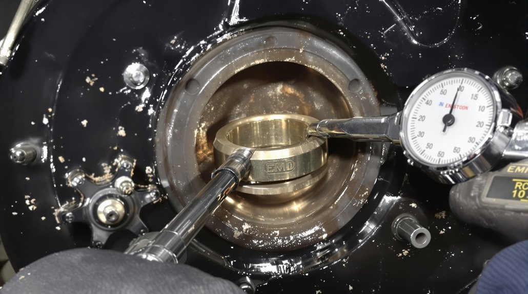
When replacing EMD diesel camshaft bearings, always use OEM-approved parts matched by exact part numbers for your engine series. Torque fasteners per EMD specs—typically 1,800 ft-lbs for crab nuts—using calibrated tools, and verify alignment with a dial indicator. Carefully measure housing bores with a ball micrometer, check for uniform gasket compression, and document all clearances for traceability. Strictly follow torque sequence and lubrication practices to guarantee reliability. For model-specific nuances, important fitment checks, and troubleshooting tips, explore further.

Key Takeaways

  • Verify camshaft bearing part numbers and compatibility using the EMD Parts Catalog and engine model identification.
  • Measure camshaft bearing bores for straightness and correct size with a dial indicator and ball micrometer before installation.
  • Install bearings with proper orientation and confirm seating, ensuring alignment and uniform interference fit per EMD specifications.
  • Torque bearing cap fasteners to EMD-specified values, following the prescribed tightening sequence for even load distribution.
  • Document all measurements, part numbers, and torque values for traceability and future maintenance reference.

Torque Settings and Fastener Tightening Procedures

torque settings ensure reliability

Before you begin reassembling the EMD diesel engine, understanding the correct torque settings and fastener tightening procedures is critical to confirm mechanical integrity and operational safety. You’ll encounter several fastener types—crab nuts, main bearing nuts, fork rod capscrews, split basket bolts, and flywheel coupling bolts—each with specific torque requirements. For example, cylinder head crab nuts on a 567-series require 1,800 ft-lbs, while main bearing nuts need 500-800 ft-lbs and must be retightened after thermal cycling.

Always follow the prescribed tightening sequence to confirm even load distribution; this is especially important for multi-piece assemblies like split baskets, where bottom bolts must be torqued to 75 ft-lbs. Use specialized tools such as the main bearing wrench set (8219512) and offset ratchets (8191591) to achieve precise results, particularly in confined spaces. Adhering to these parameters prevents distortion, maintains alignment, and confirms long-term reliability. Regularly inspect and verify proper torque specifications during maintenance operations to reduce the risk of premature bearing failure and extend the operational life of critical engine components.

Selecting and Sourcing Correct Replacement Parts

replacement camshaft bearing sourcing

Several precise steps are essential when selecting and sourcing replacement camshaft bearings for EMD diesel engines. Start by confirming part compatibility—reference EMD’s part numbering protocols, such as B18 for 645 series main bearings or B26 for camshaft drive gear trains. Always match part numbers exactly to your engine model and series, guaranteeing interchangeability within the specified engine family. Use a ball micrometer and dial indicator to verify critical dimensions, aligning with clearance tolerances (for example, 0.08–0.15 mm between governor drive gear and stub shaft).

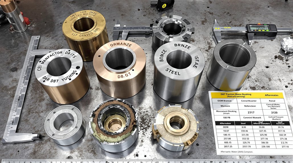
When sourcing replacement camshaft bearings, it is crucial to consider the bearing and bushing specifications—such as oversize or undersize options—to ensure the correct fit and function within your engine assembly.

For sourcing strategies, prioritize OEM-approved or EMD-licensed suppliers. Cross-reference offerings—such as 40004756 cam bearing kits—against technical documentation, and request supplier certifications and warranties. Don’t overlook the importance of component traceability; document all part numbers and measurements for future reference. By adhering to these steps, you’ll confirm reliable part compatibility and maintain operational integrity throughout the camshaft bearing replacement process.

Model-Specific Camshaft Bearing Recommendations

model specific camshaft bearing recommendations

While EMD diesel engines share foundational design principles, each model demands specific camshaft bearing considerations based on cylinder configuration, lubrication routing, and mechanical loads. For 567C engines, use flanged camshaft segment bearings designed for oil feed through the camshaft center bore and flanged caps, ensuring compatibility with both four-exhaust-valve heads and the inline-8, -12, or -16 layouts. Choose bearing materials that withstand the high loads imposed by the 7.5″ or 6.5″ crankshaft journals and select camshaft types that match your engine’s firing order and phasing—critical for V-type 8-cylinder and long-span 12-cylinder configurations.

In 645 Series engines, prioritize bearings capable of supporting the idler gear assembly’s additional drive loads and maintaining oil flow integrity through the camshaft center bore. Always verify torque specs for bearing capscrews, stubshaft brackets, and head crab nuts. Matching bearing materials to engine-specific requirements maximizes camshaft longevity and overall operational reliability.

Precision Measurement and Alignment Techniques

precision alignment and measurement

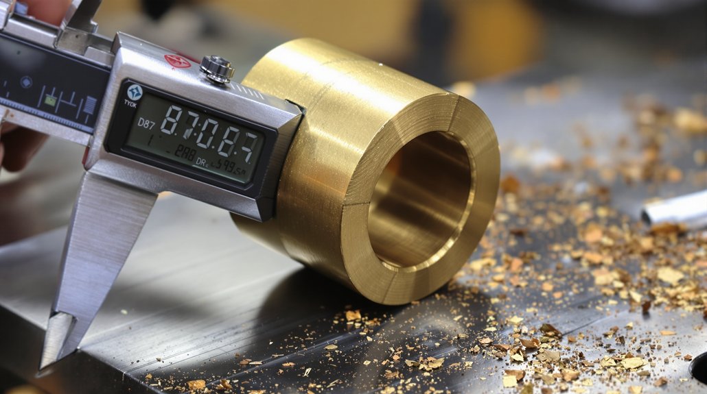
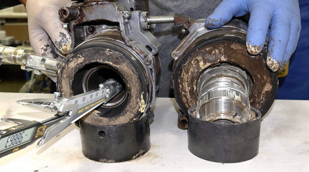
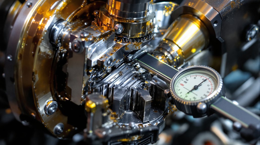
You’ll rely on dial indicators to measure camshaft bearing bore straightness and detect any alignment deviations exceeding permissible limits. Use a ball micrometer to verify precise housing bore dimensions and confirm correct bearing sizing for ideal fit. Proper positioning of bearings is crucial to avoid damage, so always ensure correct orientation during installation. Accurate readings from both tools are critical to prevent premature wear and guarantee reliable camshaft operation.

Dial Indicator Usage

A single misstep in dial indicator setup can introduce significant measurement error when replacing EMD diesel camshaft bearings. Start by confirming indicator calibration—adjust both pointers to zero using a certified test bar or base plate. Securely mount the indicator on a stable base to prevent vibration or movement that would undermine measurement accuracy. Align the spindle precisely with the measurement direction to eliminate cosine error; a 12° stylus angle is ideal, and never exceed manufacturer-specified angle limits.

Position the indicator surface parallel to the camshaft bearing surface, whether horizontal or vertical. Select contact point stiffness and geometry appropriate for your load and angle requirements. The travel range of a dial indicator—typically up to 100 mm—should be chosen to match the dimensional variation expected in camshaft bearing measurement. Always verify repeatability and retrace error by repeating measurements. Periodically check against national standards to confirm ongoing indicator calibration.

Ball Micrometer Application

Once the dial indicator confirms camshaft bearing alignment, focus shifts to precision measurement—where the ball micrometer becomes your primary tool. Begin by cleaning the ball and anvils thoroughly to eliminate contamination. Maintain environmental stability to prevent thermal expansion errors. Before proceeding, perform ball micrometer calibration using certified gauge blocks; this step validates measurement accuracy and verifies the instrument’s 0.001mm resolution.

Position the ball on a V-notched saddle for stability, centering it perpendicular to the anvils. Apply controlled, frictionless gaging pressure to avoid deformation. Measure at least three radial positions—typically at 3:00, 9:00, and 12:00—to account for out-of-roundness, then average results for statistical reliability. Take multiple measurements for reliability, as small measurement variations can impact performance. Document each reading, maintaining traceability and guaranteeing compliance with EMD diesel camshaft bearing replacement specifications.

Inspection Protocols Before and After Installation

camshaft bearing installation checks

Before installing new camshaft bearings, you’ll need to measure diametral clearances using a ball micrometer or dial indicator to confirm they meet EMD tolerances. Don’t overlook gasket inspection—verify all seals and gaskets for uniform compression and absence of defects to prevent leakage. Bearings reduce friction between the camshaft and engine block, so ensuring proper lubrication and fit is critical for longevity. After installation, recheck clearances and visually confirm gasket integrity to guarantee reliable operation.

Measuring Bearing Clearances

Even minor deviations in camshaft bearing clearance can lead to premature wear or catastrophic failure, so precise measurement protocols are essential before and after installation. Begin by measuring the main housing bore and camshaft journal diameters with calibrated micrometers, ensuring all readings are at room temperature to avoid thermal distortion. Verify bearing thickness to confirm it aligns with specified clearance tolerances; use .0003” per shell as your baseline for bimetal bearings.

Apply plastic gauges between journal and bearing shell, then torque to 650 ft-lbs, noting the compressed strip width to determine actual clearance. Document six radial bore measurements to detect out-of-round conditions. After installation, recheck clearances, compare against OEM limits, and inspect for scoring or misalignment to validate proper assembly integrity. Accurate measurement is critical for engine performance and ensures that oil clearance is within optimal specifications.

Assessing Gasket Integrity

Accurate bearing clearance measurements set the foundation for reliable camshaft operation, but maintaining gasket integrity is equally important to prevent fluid leaks and guarantee long-term engine performance. Before installation, inspect all sealing surfaces for cracks, misalignment, or signs of gasket deterioration using borescopes and visual checks. Clean surfaces thoroughly, removing old sealant and debris, then confirm flatness and roughness meet EMD specifications.

Regular inspection with fiber optic endoscopes helps identify potential failures before catastrophic damage occurs. Apply an even layer of approved sealant to critical interfaces, ensuring proper alignment of pins and bosses. After assembly, execute pressure testing and thermal cycling to detect leaks and assess gasket resilience under operational stresses. Monitor for micro-leaks, warping, or coolant seepage. Log inspection and test results, scheduling periodic follow-ups to track gasket performance and confirm ongoing seal integrity.

Best Practices for Maintenance and Longevity

camshaft bearing maintenance strategies

A disciplined approach to camshaft bearing maintenance is essential for maximizing the reliability and lifespan of EMD diesel engines. You should always begin with a thorough pre-replacement inspection—check for bearing discoloration, verify oil filter cleanliness, and analyze lube oil quality. Use only OEM-grade parts and adhere to exact torque and alignment procedures during installation to guarantee proper fitment and stress minimization. For effective longevity strategies, regular lubrication management is critical: replace turbocharger oil filters every 1,400 hours, use only approved lubricants, and flush lubrication systems during overhauls. During each major maintenance event, be sure to clean oil strainers to prevent debris buildup that could compromise bearing performance.

StepActionFrequency/Detail
Oil Filter ReplacementInstall new turbo filtersEvery 1,400 hours
Oil AnalysisCheck for contaminants/degradationPre-replacement, quarterly
Bearing Age LoggingRecord install/service datesAt every replacement
Manual ChecksInspect for roughness/heat1 & 3 months post-install
Lubricant SelectionUse OEM-approved oilsEvery fill/change

Document all maintenance actions and correlate them to boost operational longevity.

Common Fitment Issues and Troubleshooting

bearing fitment troubleshooting techniques

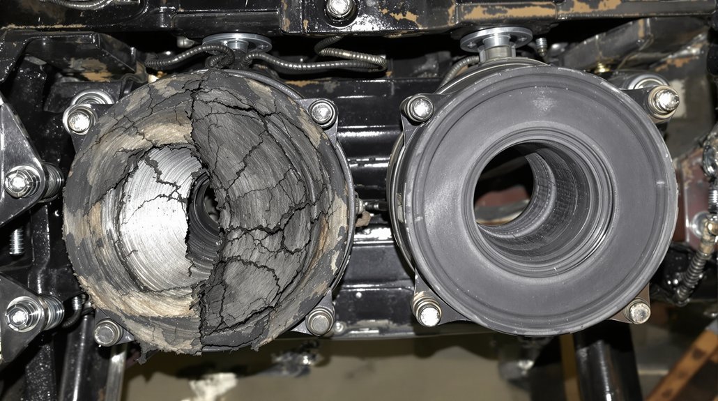
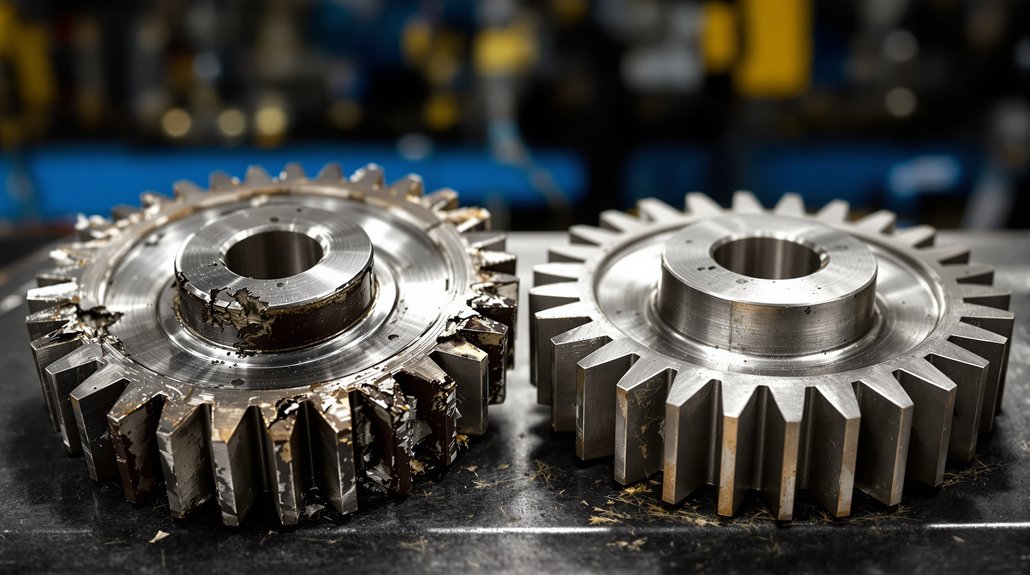
When replacing EMD diesel camshaft bearings, you’ll encounter several fitment challenges that can compromise engine reliability if left unaddressed. Common bearing fitment issues include selecting incorrect bearing sizes, which leads to misalignment and potential metal-on-metal contact. Verify bearings are oriented properly—misaligned or partially covered oil holes restrict lubrication, causing accelerated wear. Improper seating or insufficient interference fit allows bearing movement, resulting in camshaft flex and uneven support.

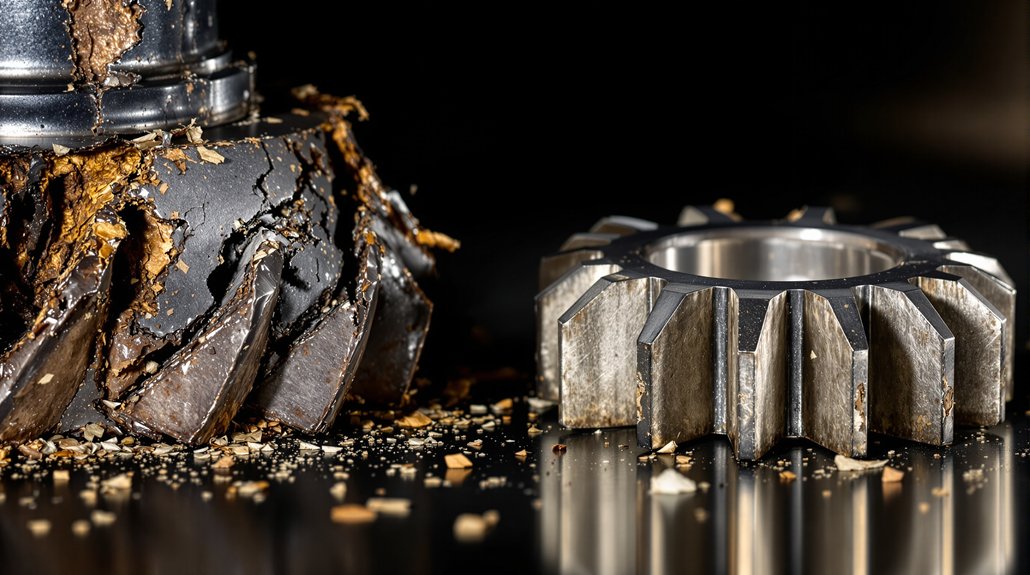
Excessive wear is often the result of improper installation or incorrect bearing sizes, and if not addressed promptly, it can lead to total bearing failure. Use troubleshooting techniques such as lift checks to confirm proper fitment before final installation. Always clean serrations in caps and frames to avoid uneven seating, and inspect for high spots or machining errors that can distort bearing geometry. After installation, check for adequate bearing contact patterns and perform post-installation rotating effort checks to identify misalignment or torque errors. Address debris contamination by thoroughly cleaning all block and cap surfaces, preventing foreign material from compromising lubrication and bearing life.

Reference Tools and Catalog Resources

emd camshaft bearing replacement resources

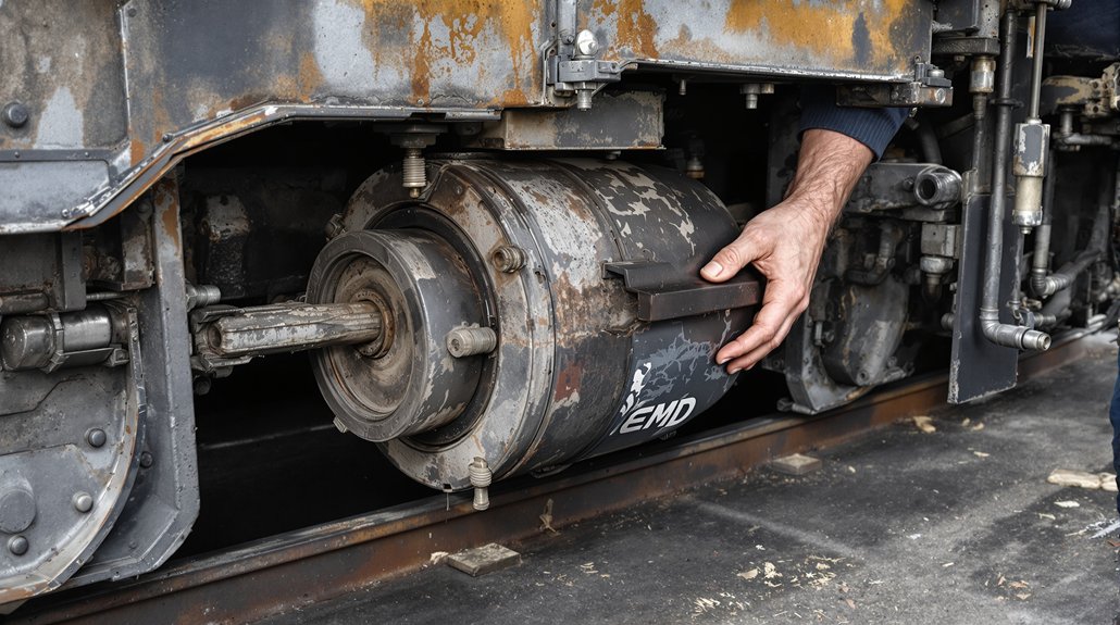
Technical manuals and catalog resources serve as essential references throughout EMD diesel camshaft bearing replacement. You’ll rely on the Square EMD 567C Maintenance Manual for engine-specific data like torque specs, firing orders, and journal diameters. This manual details the torque values for hardened (85 in-lbs) and non-hardened (65 in-lbs) fasteners, critical for precise reassembly.

For catalog organization, the EMD 645 Parts Catalog No. 302 assigns unique codes—such as A07 for camshaft and connecting rod bearings—streamlining parts identification across assemblies. Component relationships for brackets, drive gears, and speed-trip mechanisms are clarified via tabular part lists, reducing errors in ordering and installation. Cross-reference charts are indispensable for distinguishing bearing specs between 567C, 645, and F/E variants, ensuring you match the correct part to your engine model. Specialized tools like ball micrometers and dial indicators, referenced in manuals, enable accurate measurement and verification during the replacement process.

Frequently Asked Questions

How Long Does a Typical Camshaft Bearing Replacement Take?

Think of camshaft bearing replacement like performing surgery on a heavy-duty engine—precision’s essential. You’ll spend 10-30 hours, depending on engine size and access. For efficient camshaft maintenance tips, always use dial indicators to verify axial play, and follow proven bearing installation techniques, like gradual press-fit and alignment checks. Don’t rush—timing verification and injector alignment add extra hours, so plan for a two-person team to guarantee accuracy and component safety throughout the process.

Can I Reuse Old Camshaft Bearings if They Look Undamaged?

Even if old camshaft bearings look undamaged during bearing inspection, you shouldn’t reuse them. Visual checks can’t catch internal fatigue or subtle wear that compromises engine longevity. Industry standards require you to follow scheduled replacement intervals, since reused bearings risk premature failure, hidden cracks, and disrupted oil flow. Always install new bearings and hardened washers to maintain proper alignment, oil film thickness, and warranty coverage. Don’t rely on appearance—prioritize proven maintenance protocols.

You’ll notice that safety goggles, gloves usage, and steel-toe boots all coincide as essential PPE when replacing camshaft bearings. Equip yourself with impact-resistant safety goggles to shield your eyes, and heavy-duty gloves to prevent cuts and chemical burns. Don’t forget a face shield respirator for fume protection, coveralls for spill barriers, and oil-resistant matting for grip. Always keep a fire extinguisher and emergency eye wash station close for unforeseen incidents.

How Do Ambient Temperatures Affect Camshaft Bearing Installation?

When installing camshaft bearings, you must factor in temperature considerations since ambient temperatures cause housing and bearing materials to expand or contract. If you ignore this, you risk improper clearances and misalignment. Always use installation techniques that account for these changes—install bearings at recommended ambient temperatures, and use precision alignment tools. Oversized reaming may be necessary in high-heat environments to prevent distortion, ensuring reliable operation and ideal bearing-to-housing fit.

Are There Video Tutorials Available for First-Time Replacers?

Think of video resources as your roadmap through unfamiliar territory—they guide you step by step. You’ll find several video tutorials online that offer beginner tips, demonstrate bearing puller kit usage, and show precise oil hole orientation. These videos cover industry procedures like seal protrusion measurement and proper bearing handling. Watching them, you’ll gain confidence in techniques such as tool-based insertion and torque specifications, ensuring your first replacement meets OEM standards and procedural accuracy.

You may also be interested in reading – EMD Engine Maintenance Manual 567b 4th Edition

7 Tips: EMD Locomotive Bearing Tolerance Measurement

7 Tips: EMD Locomotive Bearing Tolerance Measurement

To measure EMD locomotive bearing tolerances accurately, you’ll need precision micrometers and CMMs, keeping tools well-calibrated. Check main bearing bores in 60° increments, verifying dimensions and ellipticity. Use Plastigage for clearance and confirm torque on fasteners with a calibrated wrench. Maintain parallel case surfaces and use alignment gauges for installation. Monitor vibration signatures for early faults. Document measurements against spec. If you want to guarantee top bearing reliability, the next tips detail advanced diagnostic and monitoring methods.

Key Takeaways

  • Use calibrated micron-level micrometers and CMMs to ensure all bearing measurements meet AFBMA and ISO standards for EMD locomotives.
  • Take six radial bore measurements at 60° increments, and confirm bore diameter and ellipticity are within OEM tolerances.
  • Clean all bearing and measurement surfaces thoroughly to prevent contamination errors and inaccurate clearance readings.
  • Apply and verify correct torque values on main bearing and cylinder head nuts; always check torque wrench calibration before use.
  • Document all clearance and roundness measurements, cross-referencing with manufacturer specs, and repeat checks at multiple points to detect taper or out-of-roundness.

Selecting Precision Tools for Accurate Bearing Measurements

precision tools for measurements

Precision forms the foundation of reliable bearing tolerance measurement in EMD locomotives, making your choice of tools critical for ensuring dimensional accuracy. To achieve ideal measurement accuracy, you’ll need to select instruments that match the stringent requirements of AFBMA and ISO standards. Micron-level micrometers are indispensable when checking bearing sizes and clearances, while ratchet stop micrometers guarantee consistent readings on small dimensions.

For complex geometries, coordinate measuring machines (CMMs) provide precise spatial data, but only if you adhere strictly to calibration techniques and environmental controls—temperature and vibration must be managed.

Because identifying specific bearing type is crucial for accurate measurement, always confirm the type of bearing before choosing your measuring tools and methods.

When inspecting internal diameters, pneumatic air gauges offer non-destructive micro-level resolution, and laser-based tools enable non-contact examination of delicate or large components. Always cross-verify measurements with backup tools and systematically document results. Regular calibration with certified reference standards and disciplined maintenance routines are essential for sustaining measurement accuracy. Only trained personnel should operate these tools to avoid introducing errors.

Ensuring Proper Main Bearing Bore Dimensions

main bearing bore measurements

Selecting the right measuring instruments sets the stage for achieving main bearing bore dimensions that meet EMD locomotive standards. You’ll need to check bore geometry by taking six radial measurements—three at each end of the bore in 60° increments. Verify your bore diameter averages between 8.249″ and 8.252″ under a final torque of 650 ft. lbs. Use the main bearing wrench set 82019512 through the oil pan for consistent torque, and employ the offset ratchet set 8191591 for precise nut adjustment.

Maintaining dimensional stability means monitoring out-of-round conditions; your maximum allowable ellipticity is 0.003″ at full torque. Deviation limits define the allowable measurement variations from nominal dimensions, which is crucial for ensuring EMD main bearing bores do not exceed permissible tolerances. Confirm crankcase surfaces are parallel within 0.002″ and that cap bolt torque remains symmetrical to prevent elliptical distortion. Always clean all surfaces before measurement to avoid contamination errors, and use calibrated tools to guarantee accuracy. These steps verify your main bearing bores remain within strict EMD tolerances.

Measuring Clearance With Plastigage and Micrometers

measuring bearing clearance accurately

Although main bearing bore dimensions set the foundation, verifying actual bearing clearance demands a careful approach using both Plastigage and micrometers. Start by selecting the correct Plastigage thickness—usually thinner than the expected gap—to avoid compression errors. Clean all bearing surfaces meticulously before Plastigage application, and gently place the strip to prevent inaccurate results. After assembly, compress the Plastigage, then match its width to the reference chart for precise clearance readings. If values fall outside specifications, adjust strip thickness and recheck.

For micrometer-based measurements, confirm micrometer calibration using certified reference bars before taking journal diameters or bore readings. Calculate clearance by subtracting journal diameter from housing bore. Repeat measurements at multiple points to account for taper or out-of-round conditions, always cross-referencing EMD manual tolerances. Regular measurement intervals—often every 1000 hours—help you track wear trends and ensure timely maintenance.

  • Select proper Plastigage and clean surfaces before use
  • Calibrate micrometers and measure at several locations
  • Cross-validate all readings with manufacturer specifications

Applying Correct Torque and Alignment Techniques

precise torque and alignment

A single misapplied torque or overlooked alignment check can compromise the entire EMD locomotive bearing installation. You must prioritize precise torque application for every critical component. For example, main bearing nuts require 500-800 ft-lbs, but when bore dimensions are between 8.249″-8.252″, use 650 ft-lbs. Cylinder head crab nuts need exactly 1,800 ft-lbs to prevent assembly damage, while fork rod capscrews demand 190-200 ft-lbs, with serration inspection confirming retention. Always verify your torque wrench’s calibration before use, as even minor deviations skew results.

Equally crucial is alignment verification. Use gauge #8177167 to check crankcase serrations, ensuring distortion remains within ±0.003″. Specialized P-pipe alignment tools confirm cooling nozzle positioning; replace misaligned parts immediately. Confirm shaft-to-bearing fit with calibrated micrometers, ensuring proper interference. [Integrating domain and business-oriented factors, as highlighted in Domain Driven Data Mining, can enhance the actionability and reliability of your bearing installation procedures.] Maintain your alignment tools through regular calibration for accurate readings. Thorough torque application and alignment verification are essential for reliable bearing function and long-term locomotive integrity.

Monitoring Vibration Patterns for Early Fault Detection

vibration analysis for fault detection

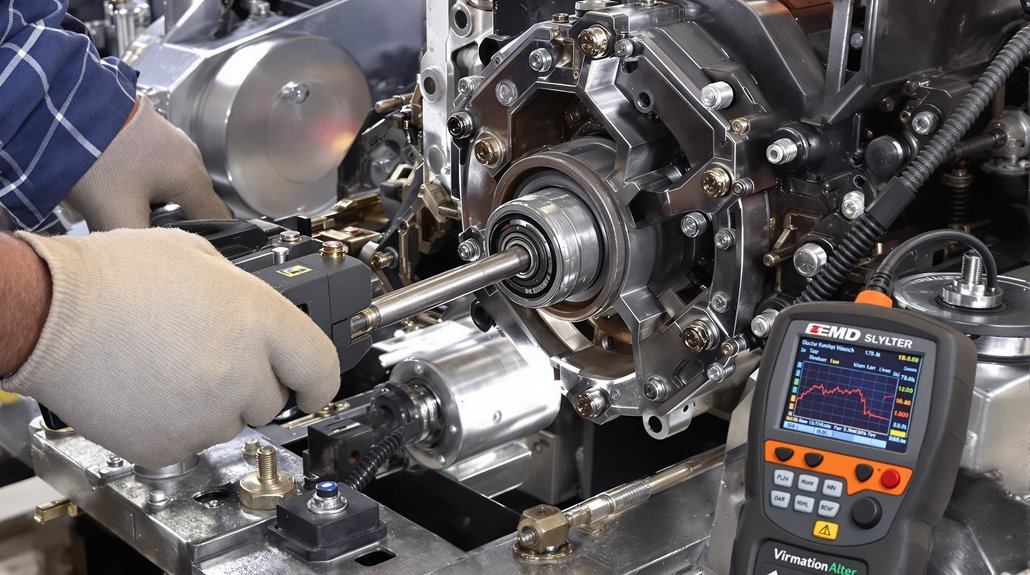
Vibration analysis offers an indispensable window into the early detection of EMD locomotive bearing faults, often revealing issues before they escalate into catastrophic failures. By monitoring high-frequency vibration signatures—particularly in the 25–100 kHz range—you can pinpoint incipient faults long before physical symptoms appear. Key vibration frequencies, such as BPFO (273.17 Hz), BPFI (335.87 Hz), and BSF (125.36 Hz), indicate specific bearing defects and help you localize emerging wear patterns.

Integrating temperature and visual inspection data with vibration analysis increases fault prediction accuracy, especially when advanced methods like Empirical Mode Decomposition (EMD) and machine learning classifiers (e.g., ELM networks) are used to extract and process fault-specific features. EMD signal processing isolates defect-specific frequencies from background noise, allowing for more accurate identification and extraction of fault features during vibration signal decomposition.

  • Track high-frequency vibration bands for earliest fault detection
  • Correlate vibration signatures with temperature and physical wear patterns
  • Apply advanced signal processing for effective fault prediction

Combining multi-sensor data and sophisticated analytics guarantees timely intervention, minimizing costly repairs and downtime.

Validating Tolerances With Manual Measurement Protocols

bearing tolerance validation techniques

To validate EMD bearing tolerances, you’ll use multipoint bore measurement methods to capture dimensional consistency across all critical locations. Apply micrometer-based roundness checks to detect any deviation from specified geometry, ensuring the bearing’s structural integrity. Follow strict clearance verification procedures with Plastigage and dial indicators to confirm alignment with EMD’s precise dimensional benchmarks. When working with journal bearings, their high surface area and reliance on hydrodynamic lubrication should be considered during tolerance checks to ensure optimal load distribution and wear compensation.

Multipoint Bore Measurement Methods

Precision underpins effective multipoint bore measurement methods for EMD locomotive bearing tolerance validation. You’ll need to start with rigorous borehole preparation techniques—verify borehole straightness and stability to prevent rod binding. Anchor placement strategies are essential: distribute stainless steel anchors at varying depths, using laser alignment to guarantee accuracy and capture both surface and structural movement. Select the number of anchors based on bore diameter—three for φ76mm, up to six for φ102mm—adhering to minimum φ101mm requirements for sensor stability.

For best results, always assume that the deepest anchor is in stable ground to ensure your displacement measurements are accurate and not influenced by unstable strata. Use fibreglass connecting rods to minimize temperature expansion errors in sensitive environments. Secure the reference head assembly with flange mounting for repeatable, stable measurements. Regularly log manual displacement readings using micrometer gauges and adhere to Abbe’s principle to minimize axis misalignment errors.

These steps guarantee reliable tolerance validation in demanding field conditions.

Micrometer-Based Roundness Checks

After establishing stable multipoint bore measurements, you’ll rely on micrometer-based roundness checks to manually validate EMD locomotive bearing tolerances. Begin by confirming your micrometer calibration against certified reference standards, ensuring sub-thousandth accuracy.

For roundness verification, use a ball micrometer at multiple clock positions—typically every 60°—on the main bearing bore, maintaining specified torque (650 ft. lbs.). The out-of-round tolerance must not exceed 0.003”, with bore diameters between 8.249” and 8.252” post-torquing. Proper liner installation techniques are essential for accurate measurement results, as precision installation techniques help prevent bore distortion and ensure repeatable tolerance verification.] Document all readings and cross-reference them with manufacturer specs. The table below summarizes essential steps:

StepTool/SpecTolerance/Limit
CalibrationReference Standard<0.0005” deviation
Measurement PointsBall MicrometerEvery 60°
Roundness LimitMain Bearing Bore≤ 0.003”

Clearance Verification Procedures

Once you’ve established roundness conformity, clearance verification procedures demand equally rigorous manual protocols to guarantee EMD locomotive bearings operate within strict tolerances. You’ll use Plastigage strips to measure bearing clearances, ensuring values remain in the critical 0.003″-0.005″ range. Precision calipers confirm bearing seat dimensions meet OEM standards, while crankshaft runout is checked with dial indicators for ≤0.002″ deflection. Frequent inspection is essential—bearing wear accelerates rapidly outside these tolerances, so schedule checks according to operational cycles and temperature trends.

  • Verify main bearing and connecting rod cap alignment with specialized gauges during the torque sequence. Regular oil analysis can further enhance predictive maintenance by identifying early signs of bearing contamination or abnormal wear.
  • Record all clearance data and compare it against OEM benchmarks for compliance assurance.
  • Adjust inspection frequency if measurements approach tolerance limits, indicating increased risk of bearing wear.

Leveraging Advanced Diagnostic Technologies for Bearing Health

advanced bearing health monitoring

While locomotive bearings operate under harsh and dynamic conditions, advanced diagnostic technologies now allow you to detect subtle signs of degradation long before catastrophic failure. High-frequency vibration analysis (25–100 kHz) isolates early fault-initiation signatures, while envelope power spectrum analysis distinguishes between inner and outer race defects by extracting characteristic frequencies. Variational Mode Decomposition (VMD) and Empirical Mode Decomposition (EMD) decompose complex, non-stationary signals into intrinsic mode functions (IMFs), letting you target fault-specific oscillations despite noise and operational variability.

Multi_correlation Analysis (MCA) further refines detection by prioritizing IMFs with high diagnostic value using metrics like NCM, MIA, and ESC. The integration of EMD and GNN-AdaBoost has also been shown to significantly improve fault diagnosis accuracy in rolling bearings, making it an effective approach for real-time monitoring and predictive maintenance in rail systems. Hybrid approaches integrate thermal and vibration data, correlating temperature deviations (≥10–20°F) with abnormal vibration for a holistic view of bearing health. Wireless data acquisition and adaptive boosting algorithms guarantee real-time, accurate monitoring, even under fluctuating speeds and loads, helping you prioritize maintenance and prevent unplanned downtime.

Frequently Asked Questions

How Often Should Bearing Tolerance Measurements Be Scheduled During Regular Locomotive Maintenance?

You should determine bearing measurement frequency based on your locomotive’s maintenance scheduling and operational demands. For most fleets, schedule tolerance checks every 92 days for basic systems, or every 184 days for advanced platforms. Increase frequency if your units experience high mileage, harsh environments, or after major overhauls. Always align your maintenance scheduling with manufacturer recommendations, ensuring you catch early wear and maintain peak performance. Regular inspections help you prevent costly failures and extend bearing life.

What Are Common Signs of Bearing Tolerance Issues During Locomotive Operation?

Think of a bearing like a heartbeat—when it skips, you sense trouble ahead. You’ll notice tolerance issues when vibration analysis reveals unusual frequency peaks or abrupt amplitude shifts. Maintenance logs might show repeated overheating, increased wear, or oil contamination events. If you spot surface pitting, debris in lubricant, or decreased clearance, act fast. These symptoms signal deeper problems that, left unchecked, can derail schedules and compromise locomotive safety.

Can Environmental Factors Affect Bearing Measurement Accuracy in the Field?

You should always consider environmental factors when measuring bearing tolerances in the field. Temperature fluctuations can cause thermal expansion or contraction, directly impacting your readings and potentially introducing calibration drift in instruments. Humidity levels also play a role—high moisture can lead to corrosion or condensation, distorting measurement points and degrading lubricants. Both factors, if uncontrolled, undermine measurement accuracy, so you need to manage environmental conditions and calibrate your tools accordingly.

When you’re starting out, prioritize online courses focused on bearing tolerance measurement fundamentals and industry standards like ISO and ABEC. Then, supplement your learning with hands-on workshops, where you’ll use micrometers, calibration kits, and torque wrenches. Seek programs offering simulations of real-world scenarios and access to technical documentation. Combine theory with practical exercises, so you’ll understand how to apply tolerance limits, identify wear, and follow correct measurement and inspection procedures.

How Do Bearing Tolerance Issues Impact Overall Locomotive Fuel Efficiency?

You might think ignoring bearing tolerance issues would boost locomotive performance, but it’s quite the opposite. Poor tolerances increase fuel consumption as friction rises, forcing the engine to work harder. Mechanical wear accelerates, leading to frequent maintenance and part replacement. You’ll also see efficiency losses because energy intended for propulsion gets wasted as heat. In short, improper bearing tolerances drain both your fuel budget and your locomotive’s operational reliability.

Why Check EMD Camshaft Bearing Clearance Specifications?

Why Check EMD Camshaft Bearing Clearance Specifications?

You need to check EMD camshaft bearing clearance specifications to guarantee you’ve got a proper oil film separating metal surfaces, preventing direct contact and wear. Incorrect clearance—too tight or too loose—risks overheating, oil starvation, or rapid bearing failure. By measuring with precise tools and confirming specs, you maintain ideal lubrication, avoid misalignment, and extend engine life. Following these checks supports reliability and helps you avoid costly failures; there are key techniques and detailed best practices to take into account next.

Key Takeaways

  • Ensures proper oil film formation, preventing metal-to-metal contact and premature camshaft or bearing wear.
  • Verifies correct bearing fit, minimizing risks of seizure, excessive vibration, or engine failure due to misalignment.
  • Detects tolerance stack-up or machining errors that could compromise load capacity and engine reliability.
  • Confirms lubricant viscosity compatibility, optimizing lubrication performance and reducing the risk of oil starvation.
  • Supports preventive maintenance by identifying abnormal wear trends before costly failures occur.

Understanding Critical Clearance Values in EMD Camshafts

optimal emd camshaft clearance

Proper clearance values form the foundation of reliable EMD camshaft operation. When you perform clearance calculations, start with the standard formula—0.00075” to 0.0010” per inch of shaft diameter. For example, a 2.000” shaft requires a baseline clearance of 0.0015”–0.0020”. In high-performance or extreme load scenarios, add 0.0005” to the upper end for added safety. Always account for tolerance stack-ups from the housing, shaft, and bearing materials, as these can introduce up to 0.0026” of variation.

Selecting suitable bearing materials is vital, since each reacts differently under operational stresses and temperature changes. For passenger engines, opt for tighter clearances to minimize noise and vibration, while heavy-duty applications need looser settings for durability. Accurate measurement is critical for engine performance, so using a plastic gauge to check main bearing oil clearance ensures the camshaft remains properly supported and lubricated. Precise clearances guarantee the oil film remains intact, preventing metal-to-metal contact and premature wear. Align your clearance calculations with the bearing material’s properties to optimize both lifespan and operational safety.

Measurement Techniques for Accurate Bearing Clearance

accurate bearing clearance measurement

Several essential measurement techniques assure accurate EMD camshaft bearing clearance assessment. Begin by selecting precision measurement tools—dial bore gauges for bearing internal diameter and micrometers with fourth-decimal precision for journal diameter. Always zero and calibrate these measurement tools at 68°F (20°C) to counter thermal expansion effects. Secure bearing caps to their specified torque and assure all surfaces are clean and oil-free for best results.

Proper clearance prevents metal-on-metal contact between engine components, which is critical for ensuring a consistent oil film and long-term reliability.

Measure vertical clearance at 90 degrees to the bearing split line, targeting front, center, and rear positions to identify taper or wear. Remove the camshaft before taking diameter measurements to avoid interference. If using telescopic feeler gauges, never force them; insert the largest size that fits easily to prevent breakage. Plastigage offers a visual method but isn’t as precise as dial gauges—use for quick checks, not critical setups. Meticulously document all clearances in a journal template to track wear trends over time.

The Role of Lubrication in Bearing Longevity

lubrication ensures bearing longevity

When you assess camshaft bearing longevity in EMD engines, lubrication quality becomes a decisive factor in preventing premature wear. You must verify the lubricant viscosity matches manufacturer specifications to maintain an ideal film thickness between bearing surfaces. This thin oil layer prevents direct metal contact, thereby reducing friction and heat generation. If you choose a lubricant with improper viscosity, you risk inadequate film formation—leading to excessive wear or heat-induced lubricant breakdown.

Always select lubricants based on operational loads, speed, and ambient temperature to ensure consistent flow and protection. Contaminated or low oil contributes to premature wear, making it essential to maintain oil cleanliness and proper levels. Over-lubrication can cause heat buildup, while under-lubrication allows metal-to-metal contact and rapid bearing degradation. Regularly audit lubricant levels and types, adhering to recommended NLGI grades and approved viscosity ranges for EMD camshaft bearings. Precision in lubricant application, contamination control, and ongoing monitoring—such as vibration analysis and thermal imaging—will help you detect early signs of lubrication failure and maximize bearing service life.

Importance of Correct Torque and Installation Procedures

precise torque for reliability

When installing EMD camshaft bearings, you must apply torque precisely according to manufacturer specifications using a calibrated torque wrench. Always follow the correct cap sequencing pattern to guarantee even load distribution and prevent distortion. These steps are critical to maintaining proper bearing clearance and avoiding premature wear. Builders and manuals recommend 15 ft.lbs torque for camshaft bearing caps, as this level helps prevent stripping of studs and ensures long-term reliability.

Precision Torque Application

Precision torque application directly impacts camshaft bearing performance and longevity. When you apply the correct torque to bearing caps and fasteners, you prevent bearing deformation and guarantee the bearing’s inner diameter remains within tight tolerances. If you under- or over-torque, you risk distorting the housing bore, leading to misalignment and uneven force distribution across the camshaft bearing. This not only reduces wear resistance but also compromises the bearing’s load-handling capacity.

Always refer to catalog-specific torque values—such as the 70–2,300 N·m range for MDEU series—and match them precisely to your engine’s specifications. Use calibrated torque tools and follow procedural steps to maintain consistent compression on bearing surfaces. Checking cam bearing housing bores for size and shape before rebuild helps avoid underlying issues that could affect bearing performance, ensuring that torque application delivers the intended benefits. This attention to precision torque protects against premature wear and mechanical failure, optimizing both performance and service life.

Proper Cap Sequencing

Although torque accuracy is essential, the correct sequencing of cap installation plays an equally critical role in guaranteeing proper camshaft bearing clearance. You need to follow a specified bolt pattern—often a cross or staggered method—to avoid uneven pressure that can distort cap alignment. Begin by hand-tightening all bolts, then incrementally apply torque values in the recommended sequence. This prevents local overloading and guarantees the oil film isn’t compromised.

Always verify that the bearing caps’ position markings align precisely with the main journal and oil passages. Use a straightedge to check that each cap maintains proper alignment along the camshaft axis. Performing visual inspection of main caps for correct seating is a key step to ensure accurate assembly. After torquing, inspect for proper seating and confirm that each bearing is fully supported, maximizing load distribution and preventing premature wear or misalignment.

Tolerance and Misalignment Risks in Camshaft Bearings

bearing clearance and alignment

You need to watch for shaft misalignment and compounded tolerance errors, as both can quickly push bearing clearance outside recommended limits. Always verify alignment and measure actual clearances, since even small deviations in housing, shaft, or bearing size stack up and create excessive or insufficient gaps. If you skip these checks, you risk rapid bearing wear, oil starvation, or camshaft seizure. Modern engines require bearings that withstand higher loads and temperatures, so proper clearance is especially important when using stronger, less forgiving materials like aluminum alloys.

Effects of Shaft Misalignment

When camshaft bearings operate under misaligned conditions, the resulting uneven load distribution and increased dynamic stresses can rapidly compromise their integrity. You’ll observe alignment effects such as localized stress concentrations, which accelerate pitting and surface fatigue. Misalignment amplifies edge loading, increasing contact pressures and causing early spalling or cracking. Vibration impact becomes significant, with both radial and axial movements intensifying dynamic forces at the bearing-to-shaft interface.

This not only escalates fretting corrosion and material wear but also generates excessive heat, degrading lubricant viscosity and promoting metal-to-metal contact. As lubricant films erode, friction rises, draining operational efficiency and boosting energy losses. Persistent misalignment leads to premature raceway damage and frequent seal failures, ultimately shortening service life and increasing maintenance demands. Regular monitoring with vibration analysis can help detect subtle changes in machinery performance, allowing for early identification and correction of misalignment before severe bearing damage occurs.

Compounded Tolerance Errors

Even small deviations in camshaft bearing clearances can escalate rapidly due to compounded tolerance errors, especially where shaft, block, and bearing manufacturing variances interact. You’ll encounter tolerance accumulation when block machining, shaft outer diameter, and bearing inner diameter tolerances stack up, pushing clearances outside ideal limits. Aluminum alloy bearings demand strict compliance—material lacks the self-compensation found in babbitt alloys, so any installation errors, such as uneven seating or surface finish irregularities, further skew clearances.

Radial clearance is measured using plastigauge, not thrust clearance, so it is crucial to use the correct method to ensure accurate results. Press-fit and interference designs introduce elastic deformation, complicating post-installation measurements. Contaminants in bearing bores or unfinished bearing seats also contribute to unpredictable clearance loss. If you don’t systematically verify with precise tools, compounded errors can increase wear, reduce load capacity, and jeopardize the camshaft’s operational reliability.

Effects of Clearance Deviations on Engine Performance

clearance deviations affect performance

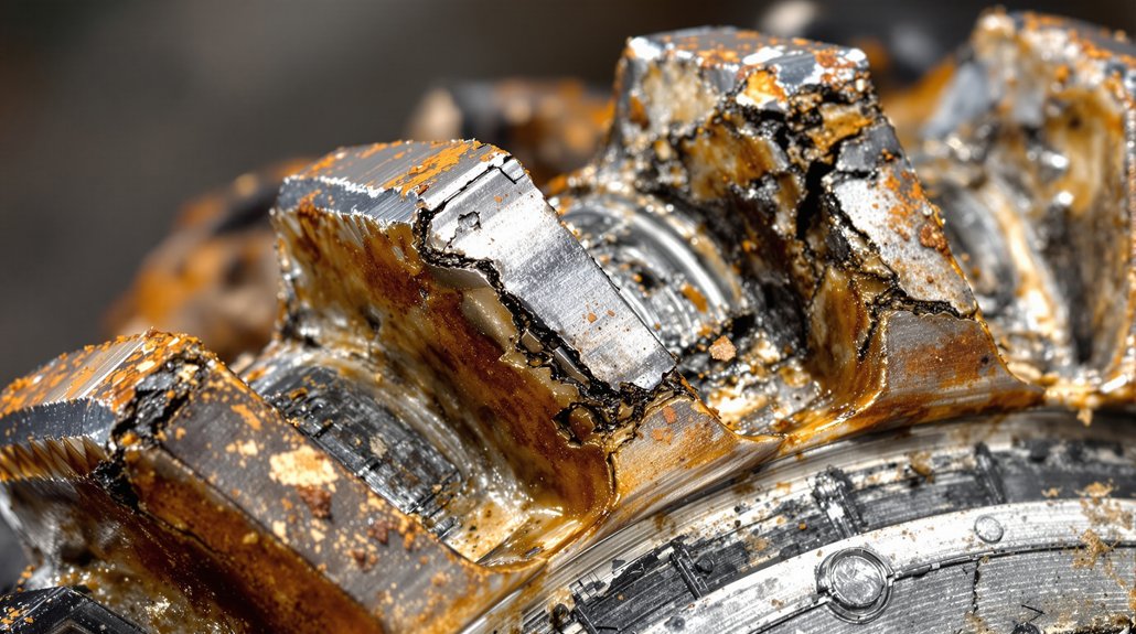
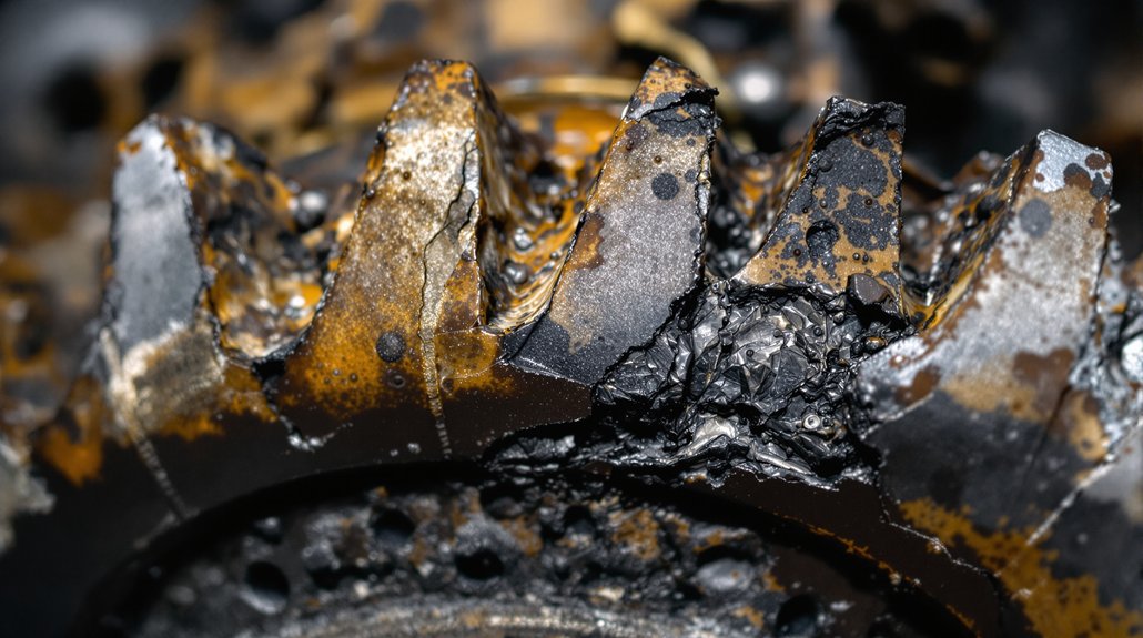
Although camshaft bearing clearance may seem like a minor specification, deviations from prescribed tolerances have immediate and far-reaching effects on engine performance. When you exceed recommended clearances, the primary clearance impact is reduced load capacity, resulting in accelerated material fatigue and overlay cracking. Fatigue cracks propagate to the steel lining, fragmenting the bearing and degrading its structural integrity—especially in turbocharged engines. Excessive clearance also creates oil leakage during cold starts, risking lubrication starvation and lifter malfunction.

Conversely, too little clearance restricts oil flow, increasing friction and heat generation. This thermal stress accelerates bearing wear and shortens component lifespan. On the timing side, increased bearing movement introduces valve phase errors, delaying valve events and reducing combustion efficiency. The cumulative effect undermines power output and responsiveness, particularly in high-compression configurations. By maintaining precise camshaft bearing clearance, you directly support performance optimization, engine reliability, and minimize costly unplanned maintenance. Typical minimum clearance around .006 is observed in older engines, indicating that both excessive and insufficient clearance can have measurable impacts even in long-running, high-mileage engines.

Lubricant Selection and Oil Submergence Guidelines

lubricant selection and submergence

Selecting the correct lubricant and establishing appropriate oil submergence are critical steps in guaranteeing ideal camshaft bearing performance. You need to match lubricant properties—especially viscosity—to the measured bearing clearance. For example, 5w20 oils suit clearances below 0.0021″, while 20w50 oils require clearances above 0.0031″. Using high-viscosity oil with minimal clearance increases temperatures and accelerates oxidation, risking lubrication failure. Conversely, low-viscosity oils with excessive clearance can’t maintain an adequate oil film, leading to metal-to-metal contact.

Oil submergence must be sufficient to keep bearings continuously supplied, preventing starvation during high-load or transient conditions. Confirm the oil level allows for proper circulation without aeration or foaming, as both degrade lubricant properties. Always adjust oil submergence based on operating conditions and engine design. By precisely aligning lubricant properties and oil submergence to your camshaft bearing clearances, you’ll optimize thermal control, lubrication efficiency, and long-term component reliability.

Maintenance Strategies for Sustaining Proper Bearing Clearance

bearing clearance maintenance strategies

To sustain proper camshaft bearing clearance, you must implement a disciplined combination of precise measurement, systematic inspection, and controlled installation practices. Start bearing maintenance by measuring crankshaft runout with dial indicators, ensuring it stays within a 0.002″ tolerance. Use Plastigage strips to verify that bearing clearance meets the 0.003″–0.005″ specification. Confirm bearing wall thickness with ball micrometers to detect wear or deformation. Adhere to proper torque values—use calibrated wrenches and follow specified patterns to achieve uniform stress on main and rod bearings.

Increase inspection frequency as components age or in high-load environments. Conduct visual inspections for water contamination, dirt scratches, and overlay flaking, referencing standardized criteria. Clean cap bores and serrations before installation to prevent misalignment. Cross-check fitment with alignment tools and validate component dimensions against OEM data. Log all clearance measurements, torque readings, and defect codes to support trend analysis and future preventive actions, ensuring long-term camshaft reliability.

You may also like to read – Symptoms of Worn Camshaft: Epic Signs for Better Diagnosis

Frequently Asked Questions

How Often Should EMD Camshaft Bearing Clearances Be Checked During Service?

You should follow camshaft service frequency and clearance inspection intervals as outlined in EMD’s maintenance guidelines. Typically, check camshaft bearing clearances during every scheduled major overhaul, after any component replacement, or if you notice abnormal engine performance. Always inspect clearances after reassembly or alignment adjustments. Regularly documenting these intervals guarantees you catch excessive wear early, maintain factory tolerances, and prevent unexpected failures, keeping your engine running reliably between service cycles.

What Are the Signs of Camshaft Bearing Clearance Issues During Engine Operation?

You’ll notice camshaft bearing clearance issues by listening for unusual camshaft noise, like clunking or tapping, especially near the valvetrain. Monitor oil pressure closely—if it drops, it can indicate excessive clearance or bearing wear. Watch for a check engine light, power loss, or engine backfiring. Inspect oil for metallic particles, and check for increased oil consumption or leaks near bearing areas, all pointing to potential clearance problems.

Can Bearing Clearance Adjustments Be Made Without Engine Disassembly?

Think of your engine as a sealed vault—bearing adjustment is like trying to fix a lock from the outside. You can’t make precise bearing clearance adjustments without engine disassembly because access to camshaft journals and bearings is blocked. For proper engine maintenance, you must remove and inspect components, measure clearances with specialized tools, and fit appropriate shells. Skipping disassembly risks inaccurate bearing adjustment and potential long-term engine damage.

Yes, you’ll find several recommended aftermarket gauges and precision tools for measuring EMD camshaft bearing clearance. Use plastic strip gauges for quick, visual clearance checks, but rely on precision micrometers and dial bore gauges for high accuracy. Pair these with dial indicators and bearing serration gauges to assess cap distortion and serration alignment. Always calibrate your precision tools before use and follow EMD-specific measurement procedures for best results and compliance.

What Training Is Required for Technicians Measuring EMD Camshaft Bearing Clearances?

To measure EMD camshaft bearing clearances accurately, you need hands-on experience with precision tools like micrometers, bore gauges, and dial indicators. Certification programs train you in reading EMD technical manuals, performing vertical and thrust clearance checks, and following torque specs. You’ll learn assembly validation, proper bearing material handling, and measurement protocols. Cross-training in tribology guarantees you understand oil film dynamics, so you can troubleshoot and maintain ideal clearances effectively.

Why Choose Specific Lubrication for EMD Locomotive Rod Bearings?

Why Choose Specific Lubrication for EMD Locomotive Rod Bearings?

You need to choose specific lubrication for EMD locomotive rod bearings because the unique alloy mixes, high loads, and rapid speeds demand precise protection. Only tailored lubricants guarantee stable film strength, reduce abrasive wear, and stand up to extreme thermal stress. The right oil also prevents galvanic corrosion between mixed metals and meets strict EPA requirements. Get this wrong, and you face early bearing failure, costly downtime, and regulatory trouble. Discover how material compatibility and performance are engineered for reliability.

Key Takeaways

  • Specific lubrication prevents premature wear and material extrusion in sensitive bearing materials like silver lead and aluminum alloys.
  • Proper lubricant selection ensures optimal film strength, stable viscosity, and reliable protection under extreme mechanical and thermal stresses.
  • Targeted additives promote heat dissipation, corrosion resistance, and film stability necessary for high-speed and high-load locomotive applications.
  • Lubricants must comply with environmental regulations, including EPA biodegradability standards, to avoid legal and operational risks.
  • Regular, specific lubrication minimizes contamination, prevents bearing failures, and aligns with EMD’s maintenance and safety standards.

Material Compatibility in EMD Rod Bearing Lubricants

lubricant material compatibility critical

When selecting lubricants for EMD locomotive rod bearings, material compatibility is critical to preventing premature wear and operational failures. You need to evaluate silver lead compatibility, since silver-lead bearings are susceptible to material extrusion during startup if oil flow is inconsistent. Lubricants must flow freely to protect these soft substrates and reduce the risk of blocked oil channels, which can cause catastrophic steel-on-steel contact. For aluminum alloy requirements, you should opt for lubricants with high film strength, as these harder materials are sensitive to marginal lubrication. If the oil film breaks down, aluminum alloys quickly wear due to their limited tolerance for direct contact.

The lubricant’s additive package must match the bearing’s unique challenges—promoting heat dissipation and corrosion resistance—while maintaining film stability between steel components. By aligning lubricant formulations with the specific silver or aluminum composition, you’ll address material-specific vulnerabilities, minimize wear, and enhance reliability under the harsh conditions locomotives routinely face.

Mechanisms of Wear Prevention in Locomotive Bearings

wear prevention in bearings

Although EMD locomotive rod bearings operate under extreme loads and temperatures, their longevity depends on a combination of precise engineering, targeted lubrication, and consistent maintenance practices. To combat wear mechanisms, you need to address both design and operational factors. Fork-and-blade configurations and optimized rod ratios reduce lateral forces and friction, while lead-tin coatings and carefully specified surface finishes guard against abrasive wear. Precise alignment guarantees lubricant distribution, minimizing surface contact and heat.

Effective lubrication strategies are essential. You should use lubricants with high-pressure additives that form protective films, and confirm thermal stability to maintain the proper viscosity under fluctuating conditions. Synthetic blends reduce boundary-layer friction, while contaminant-absorbing additives extend lubricant life. Specialized bearing sleeves and counterweighted crankshafts ensure smooth operation and optimal weight distribution, further supporting lubrication effectiveness and wear prevention. Maintenance is equally important: regular lubrication schedules, pre-application cleaning, and vigilant monitoring for contamination all help prevent bearing failure. By integrating engineering controls, optimized lubrication strategies, and disciplined maintenance, you greatly reduce wear mechanisms and extend bearing service life.

Addressing Galvanic Corrosion in Mixed-Metal Assemblies

galvanic corrosion prevention strategies

Beyond optimizing lubrication and wear prevention, you must also address galvanic corrosion risks present in EMD locomotive rod bearings assembled from dissimilar metals. In mixed metal assemblies, galvanic corrosion arises when two metals with differing electrochemical potentials contact in the presence of an electrolyte, accelerating material degradation. Start by selecting metals with minimal galvanic potential difference—pair stainless steel with nickel-based alloys rather than aluminum. Avoid high-contrast metal combinations, especially in moist environments, and consider hot dip galvanized steel or conductive elastomers with galvanically compatible particles for critical interfaces.

Integrate electrical insulation methods, such as non-conductive washers, Mylar films, or Teflon gaskets, to interrupt electrical pathways. Galvanic corrosion rates can be dramatically increased in environments with higher electrolyte conductivity, such as when saltwater or industrial contaminants are present, making environmental assessment crucial in design and maintenance planning. Apply corrosion-inhibiting pastes and consider GRE components for durable isolation. From a design perspective, control cathode-to-anode surface area ratios, use cathodic fasteners, and verify geometry prevents electrolyte retention. Finally, deploy protective coatings, surface treatments, and sacrificial anodes to shield vulnerable junctions from galvanic attack.

Environmental and Regulatory Considerations for Lubrication

eco friendly lubricant compliance guidelines

You need to guarantee your lubricant selections meet EPA biodegradability standards and use non-toxic formulations to protect surrounding ecosystems. Effective spill prevention measures are essential to minimize environmental risks and maintain compliance with rail industry regulations. By prioritizing these factors, you’ll support both operational reliability and environmental stewardship. Selecting lubricants with the proper viscosity is also crucial, as this ensures optimal film thickness and prevents excessive friction that could lead to heat buildup or bearing failure.

Biodegradability and EPA Compliance

With the advent of the EPA’s VIDA standard, compliance for EMD locomotive rod bearing lubrication now demands far stricter attention to biodegradability and environmental impact than ever before. You must select biodegradable formulations that satisfy rigorous compliance testing, as non-EAL lubricants are now strictly prohibited in regulated zones. VIDA requires lubricants to be at least 90% bio-based and demonstrate ultimate biodegradability, confirmed through EPA- or OECD-certified protocols. The stakes are high—failure to comply can result in legal penalties and operational delays. Consider what’s at risk:

  1. Hefty fines and halted operations for non-compliance
  2. Increased scrutiny during routine maintenance inspections
  3. The need to overhaul existing lubrication inventories
  4. Direct impact on your company’s environmental reputation

Even small hydraulic leaks can cause contamination of water sources and harm wildlife, so choosing VIDA-compliant lubricants is no longer optional—it’s your operational imperative.

Spill Prevention and Ecosystem Safety

Although selecting a biodegradable lubricant is essential, rigorous spill prevention and ecosystem safety measures must also be at the forefront of your lubrication strategy for EMD locomotive rod bearings. You should prioritize spill containment by choosing high-pressure-resistant lubricants and ensuring proper viscosity to minimize leaks and drips. Seal compatibility and advanced dispensing systems like wayside lubricators provide additional control, while scheduled maintenance prevents lubricant degradation and structural compromise.

For ecosystem preservation, opt for non-toxic base oils and avoid additives like ZDDP to prevent waterway contamination. Leveraging filtration systems captures blow-by contaminants, supporting regulatory compliance. Adhering to EPA emission limits and ensuring compatibility with aftertreatment systems further reduces the risk of environmental exposure, reinforcing your commitment to both operational reliability and environmental stewardship. Regular inspections help detect early signs of damage or wear, allowing you to address potential issues before they escalate and contribute to lubricant spills or bearing failure.

Performance Optimization Through Advanced Lubricants

advanced lubricants enhance performance

While EMD locomotive rod bearings operate under extreme mechanical and thermal stresses, advanced lubricants directly optimize performance by stabilizing the lubrication film and reducing frictional losses. You need lubricants engineered for precise viscosity control and film stability, ensuring the separation of bearing surfaces under dynamic loads. By selecting products with proven friction reduction and thermal adaptability, you’ll achieve consistent bearing protection even during rapid temperature shifts and high-speed operation.

Simulation studies show that increased wear clearance in bearing joints can significantly raise rough contact force, making advanced lubricants essential for preventing lubrication deterioration as components age.

Consider these critical performance benefits:

  1. Fuel Efficiency – Proper lubricant viscosity and friction reduction can cut fuel consumption by up to 31%, directly impacting operational costs.
  2. Component Longevity – Enhanced film stability protects bearings from premature wear, minimizing unplanned outages.
  3. Load-Bearing Reliability – Advanced lubricants maintain integrity under high loads, supporting the demands of modern engines.
  4. Thermal Resilience – Superior thermal adaptability keeps lubrication effective, even during severe cyclic temperature changes.

Choose advanced lubricants to safeguard rod bearing performance and reliability.

Monitoring and Maintenance for Rod Bearing Health

rod bearing maintenance protocols

To keep EMD locomotive rod bearings performing reliably, you need to follow strict oil sampling protocols, maintain scheduled lubricant replacement, and use precise clearance measurement techniques. Regularly collect oil samples for analysis to detect early signs of contamination or wear, and always replace lubricants according to OEM intervals to prevent film breakdown. Use calibrated tools to check bearing clearances, ensuring ideal alignment and load distribution throughout each maintenance cycle. Scheduled inspections of critical components help ensure safety and efficiency in rod bearing operation.

Oil Sampling Best Practices

Consistent and precise oil sampling forms the foundation for effective monitoring of EMD locomotive rod bearing health. You must apply standardized sampling techniques to achieve reliable lubricant analysis. Always collect samples from hot engines—preferably during operation or immediately after shutdown—to prevent particle settling and guarantee representative results. Use in-line valves before filters when available, and always flush drains before sampling. Maintain strict timing, compartment, and method consistency to enable accurate trend analysis. Meticulously label every sample with running hours and context, essential for tracking wear patterns.

You should obtain three to five repeated samples over time to ensure the accuracy of your trend analysis and health assessments.

Implement these best practices to avoid costly oversights:

  1. Take samples at consistent temperatures and operational states.
  2. Use dedicated, contamination-free sampling kits.
  3. Prioritize ideal sample points for accuracy.
  4. Record and correlate operating hours and conditions for clear diagnostics.

Your diligence guarantees rod bearing longevity.

Scheduled Lubricant Replacement

Anyone responsible for EMD locomotive rod bearings knows that scheduled lubricant replacement is more than a routine task—it’s a critical safeguard against premature wear and catastrophic failure. You must strictly follow scheduled lubricant timelines as defined by EMD’s maintenance program adherence, aligning lubricant changes with component refresh cycles—especially for lower main bearings, which typically dictate intervals.

For systems like traction motors, change lubricants every 2–3 years or based on megger test results. During post-assembly, apply fresh lubricants per torque specifications to prevent twisting and contamination. If you encounter overheated bearings, execute preemptive lubricant replacement as part of corrective maintenance. Always log replacements and correlate with bearing age codes, ensuring documentation meets program requirements. Consistent adherence protects rod bearing health and maximizes service life.

Clearance Measurement Techniques

Adhering to scheduled lubricant replacement sets the foundation for reliable rod bearing performance, but maintaining ideal health requires precise clearance measurement techniques. You must prioritize measurement accuracy and robust clearance assessment to guarantee long-term reliability. Use telescopic feeler gauges, dial indicators via LO pipes, CLEVITE 77 Plastigage®, and torque-applied dial bore gauges for thorough evaluations. Proper alignment—90° piston positioning, vertical measurement axes, and steady crank support—minimizes eccentricity errors and guarantees repeatable results.

Routine measurement intervals are essential, as clearances should be checked every 1000 hours to ensure they remain within manufacturer specifications and to identify any early signs of excessive wear.

Consider these critical steps for dependable monitoring:

  1. Triangulate measurements at the front, center, and rear for housing irregularity detection.
  2. Apply uniform torque before measuring to avoid distortion.
  3. Calibrate gauges regularly to prevent systemic errors.
  4. Analyze wear rates over time to catch early degradation.

Get these right, and you’ll avoid catastrophic failures.

Application Technologies for Effective Lubricant Delivery

efficient lubricant delivery technologies

Although EMD locomotive rod bearings operate under extreme pressures and temperatures, precise application technologies guarantee effective lubricant delivery and protect critical components from premature wear. You rely on gear-driven scavenging pumps that circulate oil at 390 GPM, ensuring all bearings receive a steady supply, even under high-load cycles. Oil filtration is integral—strainers remove particulates before oil pressurization, while routine maintenance prevents blockages that could compromise flow to critical rod surfaces.

Integrated oil coolers stabilize lubricant viscosity, minimizing the risk of thermal degradation that can lead to tacky residues and increased friction. Soak-back systems pre-lubricate turbochargers at restarts, reducing lubricant starvation and wristpin bearing damage. To further boost protection, you select oils with robust lubricant additives designed for high adhesion and film strength, maintaining hydrodynamic separation between metal surfaces.

Another important feature is that the main lubricating oil system contains a thermostat that will shut down the engine if oil temperature exceeds 270°F, ensuring that rod bearings are not exposed to overheating and potential failure. Together, these technologies mitigate start-up lag, prevent material extrusion failures, and extend component life through targeted, efficient lubricant delivery.

Comparing Lubricant Types for EMD Rod Bearing Systems

optimal lubricant selection criteria

When selecting lubricants for EMD rod bearing systems, you must account for the distinct operational demands, bearing types, and lubrication system constraints inherent to locomotive engines. Lubricant viscosity and grease selection are pivotal—high-speed connecting rods need low-viscosity oils for rapid flow through rifle-drilled crankshafts, while main bearings require stable viscosity at idle speeds (as low as 200 RPM) to maintain the minimum 10 PSI oil pressure. Traction motor bearings typically demand lithium-based NLGI 3 mineral greases, whereas U-tube bearings benefit from synthetic NLGI 2 greases, which excel in high-temperature environments and longer intervals between overhauls.

Optimal lubricant selection for EMD rod bearings hinges on engine demands, bearing types, and precise viscosity for reliable locomotive performance.

The wrong lubricant choice can cause rapid wear, contamination, and catastrophic failures. Consider these critical factors:

  1. Will your lubricant viscosity maintain film strength at both high and low RPM?
  2. Is your grease selection compliant with OEM specs like D50E34 or D6A2C17?
  3. Can your lubricant endure extended service intervals and harsh environments?
  4. Are you guarding against contamination and misalignment-driven lubricant loss?

Frequently Asked Questions

What Is the Typical Lifespan of EMD Rod Bearing Lubricants Under Normal Conditions?

You’ll typically see EMD rod bearing lubricants last anywhere from 12 to 24 months under normal, clean service conditions. Lifespan analysis depends on factors like lubricant degradation, contamination, and duty cycle. Regular oil analysis—checking for metal particulates and additive depletion—lets you predict remaining service life. If you maintain strict controls on water and dirt ingress, adhere to OEM drain intervals, and monitor lubricant degradation, you’ll optimize both lubricant and bearing longevity.

How Do Temperature Extremes Affect Lubricant Performance in EMD Rod Bearings?

Imagine your lubricant as a protective shield—when temperature extremes hit, that shield can thin or break. You’ll see temperature stability falter as viscosity changes, making the oil too thin in heat or too thick in cold. This leads to poor film thickness, metal-to-metal contact, and premature wear. Without careful attention to temperature and viscosity, you risk breakdowns, debris buildup, and costly EMD rod bearing failures sooner than you’d expect.

Are There Emergency Procedures if Lubricant Delivery Fails During Operation?

If you experience lubricant delivery failure during operation, you must activate emergency protocols immediately. Shut down the engine using the governor-controlled or EMDEC emergency shutdown systems to prevent bearing damage. Inspect for pressure loss, clogged filters, or pump failures. While there aren’t true lubricant alternatives on hand, you might use manual oil priming as a last resort during troubleshooting. Always isolate damaged systems and follow lockdown procedures to avoid collateral damage to adjacent bearings.

Can Lubricant Choice Impact Warranty Coverage for EMD Locomotive Components?

Think of your warranty like a lock and lubricant choice as the right key—use the wrong one, and you’re locked out. If you ignore lubricant specifications, you risk major warranty implications. OEMs require approved products and strict maintenance logs. If you use non-compliant lubricants, or fail to follow storage and application guidelines, warranty claims can be denied after failure analysis. Always choose the right lubricant to protect both your bearings and your coverage.

What Training Do Maintenance Crews Need for Handling Specialized Lubricants?

You need specialized training to handle lubricant safety effectively when working with advanced lubricants. You’ll learn how to use PPE, manage spill containment, and properly store or dispose of lubricants. Training covers interpreting lubricant characteristics, understanding chemical compatibility, and recognizing viscosity requirements. You’ll also practice diagnostic techniques like oil sampling and bearing inspections, guaranteeing you apply lubricants accurately and safely. This approach reduces equipment risk and guarantees regulatory compliance during all maintenance procedures.

Why Are EMD Locomotive Bearing Failures Hard to Diagnose?

Why Are EMD Locomotive Bearing Failures Hard to Diagnose?

You’ll find EMD locomotive bearing failures tricky to diagnose because the vibration signals are highly nonlinear, with frequent bursts and overlapping frequencies that mask true fault signatures. Variable speeds and dynamic operational loads further distort these signals, while electrical and environmental interference introduce diagnostic ambiguity. Standard tools often miss early-stage defects due to these complexities. You’re also up against challenges from limited sample diversity and the computational limits of real-time analysis. There’s more to understand about overcoming these intricate diagnostic barriers.

Key Takeaways

  • Bearing vibration signals are non-stationary and nonlinear, making fault signatures difficult to isolate with standard analysis techniques.
  • Overlapping fault frequencies and transient noise obscure early-stage defect signals, complicating accurate fault detection.
  • Low-energy faults are masked by operational vibrations and background noise, challenging the sensitivity of traditional diagnostic tools.
  • Limited and imbalanced sample data hinder the training and validation of robust diagnostic algorithms for real-world EMD applications.
  • Advanced signal processing methods require high computational resources, restricting real-time, onboard diagnosis in complex locomotive environments.

Complexities of Vibration Signal Characteristics in Bearings

complex bearing vibration analysis

Although bearing vibration signals in EMD locomotives might appear straightforward, their underlying complexity arises from pronounced non-stationarity, non-linearity, and multi-source interference. When you analyze these vibration patterns for fault detection, you encounter signals with time-varying amplitude modulation and intermittent bursts, reflecting evolving fault conditions and random impacts. The non-periodic nature of these patterns means you can’t rely on fixed-frequency analysis; instead, you must adapt your approach to capture locality-specific features.

Non-linear phenomena further complicate matters, as modulation frequency interactions and harmonic generation obscure primary fault frequencies, leading to asymmetric energy distribution across intrinsic mode functions. Mixed-frequency events—rotational, cage, and bearing pass frequencies—overlap, making spectral separation challenging.

Analyzing the vibration spectrum for peaks at calculated frequencies helps identify bearing faults, but in the case of EMD locomotives, these characteristic frequencies are often masked by noise and overlapping signals, reducing diagnostic clarity. Environmental and operational interferences, such as gear meshing, axle alignment shifts, and thermal modulation, introduce extraneous components that mask subtle fault signatures. Ultimately, accurate fault detection demands advanced, adaptive analysis to distinguish genuine bearing failures from overlapping or contaminated vibration patterns.

Challenges in Adaptive Signal Processing Techniques

adaptive signal processing challenges

Given the intricate, non-stationary nature of bearing vibration signals in EMD locomotives, adaptive signal processing techniques face significant hurdles in extracting reliable fault indicators. You’ll encounter particular challenges with low-energy signal detection, as weak periodic fault features often become masked by heavy background noise and operational vibrations. Traditional singular value decomposition (SVD) methods may neglect subtle fault-related components, requiring you to adopt advanced signal decomposition strategies like FDMK-SVD, which emphasize minor fault patterns but add coding complexity.

Monitoring vibration signals is critical for diagnosing the condition of locomotive rolling bearings, making it essential to develop more robust and sensitive signal analysis approaches. Adaptive algorithms such as variational mode decomposition (VMD) demand ideal parameter tuning—an often computationally expensive process, especially when using dynamic methods like particle swarm optimization (PSO). Additionally, you must balance denoising with the preservation of weak fault signals, since multi-source noise can corrupt resonance demodulation and mask true fault frequencies. Ultimately, real-time implementation and the dependency on accurate parameter selection complicate robust fault identification in these harsh locomotive environments.

Spectral Overlap From Multiple Fault Sources

fault frequency band analysis

When you analyze locomotive bearing signals, you’ll encounter overlapping fault frequency bands caused by nonlinear interactions among multiple defective sources. These interactions can mask high-frequency fault signatures, especially when stronger low-frequency components dominate the spectrum. Accurate fault isolation requires advanced techniques to distinguish individual contributions and mitigate spectral interference. In such cases, empirical mode decomposition can be particularly valuable, as it is capable of separating nonlinear and non-stationary signal components for improved fault diagnosis.

Overlapping Fault Frequency Bands

While analyzing EMD locomotive bearing signals, overlapping fault frequency bands present a formidable challenge to accurate fault isolation. Overlapping frequencies arise when harmonics from stator currents, mechanical resonances, and transient noise coincide with expected bearing fault signatures. This spectral convergence leads to significant signal contamination, making it difficult to distinguish weak fault indicators from dominant operational vibrations. As a result, diagnostic accuracy suffers because conventional spectral analysis and filtering techniques struggle to separate multiple, simultaneous fault sources.

Additionally, early-stage defects emit low-magnitude features that are easily masked, complicating fault classification. Frequency drift from temperature shifts and load variability further spreads fault energy across adjacent bands. Notably, vibration signal analysis is considered the most effective method for bearing assessment and diagnosis, but even advanced methods like EMD can be challenged by complex spectral overlaps. Ultimately, overlapping fault frequency bands undermine your ability to reliably isolate, classify, and interpret true bearing failures in complex EMD locomotive environments.

Nonlinear Signal Interactions

Overlapping fault frequency bands complicate signal interpretation, but nonlinear interactions among multiple fault sources introduce an additional layer of diagnostic ambiguity. You’ll encounter nonlinear phase coupling, where defect frequencies and their harmonics blend, mimicking healthy signatures and triggering false alarms. Quadratic nonlinear interactions generate composite frequencies—such as ( omega_1 + 2omega_2 )—that obscure the true origin of fault signatures.

Amplitude modulation from mechanical fatigue induces sidebands, often overlapping with harmonics from adjacent rotating elements. Standard linear analysis like FFT fails to resolve these nonlinearities, while bispectral analysis exposes hidden interactions, including complex summations and difference tones. Dynamic coupling between drivetrain components further complicates isolation, as time-varying load and speed conditions modulate nonlinear interaction strength, altering the spectral landscape and masking root causes.

Masking of High-Frequency Faults

Even as advanced diagnostics promise deeper insights, high-frequency bearing fault signatures often remain masked by spectral overlap from multiple locomotive subsystems. You’re contending with multi-component vibration sources—engine harmonics, gear meshing, and wheel-rail impacts—all generating signals within similar frequency bands. This high frequency masking obscures weak, early-stage bearing anomalies, especially as predictable harmonics dominate the spectrum. Non-stationary operating conditions further complicate fault detection, as bearing signals dynamically shift, challenging both fixed and adaptive filtering techniques.

Composite faults introduce additional spectral overlap, making it difficult to isolate individual failure modes. Feature extraction methods, such as MODWPT or EEMD, risk discarding critical high-frequency data through aggressive dimensionality reduction. Consequently, your ability to detect subtle bearing faults is constrained by the inherent complexity of overlapping spectral content. Real-time monitoring of motor bearing conditions is essential for early fault diagnosis, yet these spectral overlaps significantly reduce the effectiveness of both traditional and modern diagnostic approaches.

Impact of Dynamic Loads and Real-World Operating Conditions

dynamic loads complicate diagnostics

How do dynamic loads and unpredictable operating conditions challenge reliable bearing fault detection in EMD locomotives? You’ll find that dynamic load effects and operational variability introduce significant diagnostic complexities. Fluctuating speeds, variable cargo loads, and changing track conditions shift vibration signal characteristics, making consistent fault signature extraction difficult. Operational variability causes time-varying stress distributions, which mask or distort vital fault features. The real-world environment—temperature swings, lubricant degradation, and mechanical wear—further compounds this challenge, embedding nonlinearities and transients into the data. These factors generate non-stationary signals that traditional algorithms struggle to interpret.

Traditional fault detection methods such as vibration monitoring and spectral analysis can be insufficient in these scenarios because they may not accurately capture the evolving and overlapping fault signatures present in locomotive bearings.

Consider how these issues manifest:

  • Vibration signals fluctuate unpredictably with dynamic load effects, degrading feature extraction reliability.
  • Fault signature frequencies shift under operational variability, confusing pattern recognition tools.
  • Short-duration bearing faults get buried in background noise during rapid load changes.
  • Overlapping frequencies from simultaneous faults and adjacent component vibrations obscure true bearing signals.

Accurate diagnosis demands robust, adaptive approaches attuned to real-world variability.

Electrical System Interference and Diagnostic Ambiguity

electrical interference complicates diagnostics

While EMD locomotive bearing fault diagnostics heavily rely on vibration analysis, electrical system interference often introduces significant ambiguity into the process. Electrical disturbances—such as short circuits, power fluctuations, and faulty ground circuits—can disrupt sensor performance, resulting in spurious noise and inaccurate vibration signatures. These disturbances degrade diagnostic reliability by masking or mimicking characteristic bearing frequencies, making it difficult to distinguish between mechanical faults and electrically induced anomalies.

Signal quality inconsistencies from unstable power supplies further compromise the integrity of vibration data. Overlapping frequency spectra, for example, blur the distinction between cage defect signatures and power fluctuation artifacts. EMI can corrupt intrinsic mode function decomposition, rendering advanced fault identification methods like EEMD less effective. Additionally, incomplete datasets from battery failures hinder adaptive model training, while intermittent electrical interference disrupts continuous monitoring of critical frequencies. Ultimately, these factors create a complex diagnostic environment where electrical and mechanical fault signatures frequently overlap, compounding root cause analysis challenges.

A major challenge is the insufficient fault samples available for effective diagnosis, especially when electrical noise disrupts data collection and limits the number of usable vibration records.

Preventive Maintenance Obstacles in Accurate Detection

challenges in preventive maintenance

Despite the sophistication of modern diagnostics, several obstacles undermine the accuracy of preventive maintenance for EMD locomotive bearings. When you implement preventive strategies and maintenance protocols, you’re often challenged by the complexity and variable nature of these systems. Component interactions, weak fault signals, and inconsistent record-keeping all contribute to missed or delayed detections. Operational priorities frequently shift focus away from bearings, weakening the foundation of systematic monitoring.

Modern diagnostics face persistent hurdles—complex systems, subtle faults, and shifting priorities all undermine effective preventive maintenance for EMD locomotive bearings.

Key obstacles include:

  • Fragmented maintenance records that fail to capture critical vibration or thermal parameters, complicating trend analysis. Vibration signatures of deteriorating assemblies can serve as early warning indicators of potential failures, but without consistent and accurate record-keeping, these crucial patterns may go unnoticed or misinterpreted.
  • Incomplete lubricant analysis and non-standardized part replacements, which introduce contamination and dimensional inconsistencies, creating new failure pathways.
  • Variable operating conditions that modulate fault signatures, reducing reliability in detection metrics and masking early warning signs.
  • Conflicting maintenance priorities that delay or de-emphasize bearing-specific monitoring in favor of higher-profile components.

To enhance detection, you must address these gaps in preventive strategies and standardize maintenance protocols for sustained reliability.

Limitations of Current Diagnostic Tools and Algorithms

nonlinear vibration signal challenges

You face major obstacles when interpreting nonlinear vibration signals, as typical algorithms lack robustness against complex bearing fault signatures. Limited sample data further restricts your ability to train and validate models for rare or emerging defect patterns. Additionally, real-time analysis imposes heavy computational loads, often exceeding the resources available for onboard diagnostic systems. Furthermore, the selection of bearing materials complicates diagnostics, since different compositions and structures can produce unique wear patterns and vibration profiles that standard algorithms may not be equipped to recognize.

Nonlinear Signal Interpretation Challenges

Although empirical mode decomposition (EMD) has advanced fault detection in EMD locomotive bearings, nonlinear signal characteristics still hamper accurate interpretation. You’re challenged by nonlinear dynamics and signal entanglement, as multiscale interactions embed fault signatures within operational noise and transients. EMD’s intrinsic mode functions (IMFs) often exhibit modal mixing, so consecutive IMFs may share overlapping frequencies, obscuring discrete fault components. Selecting the appropriate IMFs—whether manually or automatically—remains subjective and error-prone due to the lack of universal criteria. Additionally, variable operating conditions shift frequency and amplitude characteristics, further complicating interpretation. Insufficient fault samples hinder traditional deep learning model performance, making it difficult for data-driven tools to compensate for these interpretive challenges. Consider these persistent hurdles:

  • Multiscale nonlinear interactions and signal entanglement.
  • Modal mixing disperses fault energy across IMFs.
  • Subjective, inconsistent IMF selection.
  • Operating condition variability alters diagnostic signatures.

These factors collectively limit diagnostic precision and reliability.

Insufficient Sample Data Issues

Nonlinear signal interpretation challenges compound further when field data for EMD locomotive bearing diagnostics remains insufficient and unbalanced. Data scarcity severely limits your ability to develop robust algorithms, especially when healthy bearing signals dominate datasets while critical failure samples—particularly multi-fault patterns—are rare.

This lack of sample diversity means diagnostic tools often overfit to common cases and miss less frequent but consequential compound faults. You’ll find that noise from MHz-order interference and environmental fluctuations, along with variable rotational speeds, corrupts already limited failure data, reducing the reliability of extracted features. Methods like KPCA and ELM require extensive, diverse labeled samples for accurate calibration, but field conditions rarely provide them. Ultimately, diagnostic accuracy suffers because sample-driven algorithms can’t generalize to real-world, multi-fault EMD bearing scenarios.

Computational Resource Constraints

While advanced signal processing algorithms have improved EMD locomotive bearing diagnostics, their computational demands create significant barriers to real-time implementation. You’ll find that diagnostic algorithms like EEMD and Hilbert transforms require high computational efficiency, especially when dealing with adaptive signal decomposition and marginal spectrum derivation. Multi-fault detection and noise mitigation further challenge real-time applicability, as simultaneous frequency analysis and complex filtering intensify resource consumption. Addressing these computational resource constraints is critical for timely and accurate failure identification. Consider these limitations:

  • Heavy resource usage for adaptive decomposition and instantaneous frequency analysis
  • Latency from multi-fault detection and high-speed signal processing
  • Overhead from automated IMF selection and calibration for consistent quality
  • Strained processing due to noise mitigation in variable-speed, non-stationary locomotive environments

Optimizing these diagnostic algorithms remains essential for effective, on-board monitoring.

Real-Time Monitoring and Computational Efficiency Constraints

real time bearing health monitoring

Given the dynamic operational environment of EMD locomotives, real-time monitoring of bearing health demands signal processing approaches that can handle both non-stationary vibration patterns and significant computational constraints. You must implement real time optimization in your data acquisition system to capture multi-channel, high-frequency signals under fluctuating speed and load profiles. These non-stationary signals violate typical assumptions, requiring adaptive decomposition methods like EEMD, which greatly increase computational load.

Effective dimensionality reduction—using KPCA, for example—reduces redundant features but introduces additional parameter tuning and delays. Ensemble EMD methods, while robust to noise, strain on-board processors and delay diagnostic output due to repeated decompositions and confidence index calculations. Neural network approaches, especially ELMs with high hidden node counts, offer high accuracy but at the cost of increased training and tuning overhead, challenging real-time deployment. Composite fault pattern recognition is further complicated by overlapping spectral features and noise, demanding precise, computationally intensive signal analysis.

Frequently Asked Questions

What Are the Typical Warning Signs of Bearing Failure Experienced by Train Operators?

Have you ever noticed sudden changes in vibration or abnormal heat signatures while monitoring your train? You’ll often spot warning signs of bearing failure through vibration analysis, detecting excessive or erratic vibration patterns, and temperature monitoring that reveals rising bearing temperatures or thermal discoloration. Pay close attention to high-pitched or metallic noises, inconsistent oil pressure, and oil contamination. These analytical indicators help you identify bearing distress before a catastrophic failure occurs.

How Long Do EMD Locomotive Bearings Usually Last Under Normal Conditions?

You can expect EMD locomotive bearing lifespan to reach approximately 500,000 to 750,000 miles under normal conditions, provided you follow recommended maintenance practices. Replace bearings at 80% of their calculated service life to prevent unexpected failures. Adhere to strict oil change intervals, monitor temperatures, and conduct routine vibration analysis. If you maintain clean environments and guarantee proper load distribution, you’ll greatly extend the operational lifespan of your locomotive bearings.

Are There Industry Standards for Locomotive Bearing Monitoring and Replacement Intervals?

You’d think bearing maintenance and monitoring standards would be universal, given the stakes, but don’t hold your breath. Instead, you’ll navigate a patchwork of manufacturer guidelines and operator-specific practices. There’s no industry-wide consensus on monitoring frequencies or replacement intervals—just a collection of best guesses and confidence index arithmetic. Without standardized protocols, you’re left interpreting disparate algorithms, balancing dataset quality, and hoping your preventive efforts outpace the next unexpected bearing failure.

What Role Does Lubrication Quality Play in Bearing Failure Rates?

You need to recognize that lubrication quality directly shapes bearing failure rates, regardless of lubrication types or bearing materials. If you use improper lubricants—incorrect viscosity, contaminated, or incompatible with bearing materials—you accelerate wear and risk overheating. Inadequate oil film thickness allows metal-to-metal contact, while particulate or water contamination causes microcracks, rust, and additive breakdown. By optimizing lubricant selection and maintaining strict contamination control, you dramatically reduce premature bearing failures and extend operational lifespan.

Can Remote Monitoring Technologies Help Reduce Unplanned Locomotive Downtime?

Think of remote monitoring as having a watchful sentinel riding every mile with your locomotive. You’ll leverage remote diagnostics and predictive maintenance to catch faults early, using real-time vibration analysis and IoT connectivity. These technologies alert you to abnormal patterns, letting you address issues before they snowball into unplanned downtime. By automating data capture and analysis, you’ll minimize manual errors, optimize maintenance, and keep your locomotives running on schedule and under control.

What Indicates EMD Bearing Wear Patterns?

What Indicates EMD Bearing Wear Patterns?

You’ll identify EMD bearing wear patterns through vibration signatures in the 25-100 kHz range, temperature rises of 10-20°F above baseline, and physical indicators like diagonal scoring marks and metal transfer deposits. Monitor acoustic emissions for micro-cracking events, check for burnt grease coloration changes, and measure film thickness shifts. Advanced EMD signal processing reveals fault frequencies while physical inspection shows spalling and surface irregularities that indicate specific wear stages and failure progression.

Key Takeaways

  • EMD signal processing decomposes vibrations into IMFs, revealing fault patterns with inner race showing variable signatures and outer race exhibiting consistent patterns.
  • Temperature rise patterns of 10-20°F above baseline indicate early bearing degradation, while sudden spikes exceeding 180°F signal potential lubrication failure.
  • Acoustic emissions in 25-100 kHz range capture micro-cracking events, evolving from high-frequency bursts to low-frequency emissions as wear progresses.
  • Physical wear indicators include shallow scoring, aluminum transfer, diagonal patterns, and darkened bearing backs from thermal overload conditions.
  • Advanced spectrum analysis using singular value difference method identifies bearing defects at specific frequencies while reducing false alarms by 25-35%.

Vibration Analysis Methods for EMD Bearing Wear Detection

emd for bearing diagnostics

When you’re diagnosing EMD bearing wear through vibration analysis, you’ll need to understand that different techniques excel at detecting specific fault stages and damage patterns. EMD signal processing decomposes complex vibrations into Intrinsic Mode Functions, enabling precise bearing fault localization by isolating defect-specific frequencies from background noise.

You’ll achieve superior fault feature extraction through vibration signal decomposition, particularly when analyzing non-stationary signals under varying operational condition analysis. This technique outperforms traditional methods by adapting to changing load and speed conditions without requiring predetermined frequency bands. The EMD method demonstrates significantly lower computational processing time compared to ensemble EMD while maintaining diagnostic accuracy.

Your noise reduction techniques become more effective as EMD separates bearing-related IMFs from external vibration sources. However, you’ll need expertise in bearing defect classification to correlate IMF energy distribution shifts with physical damage mechanisms. Early-stage defects manifest as energy concentration in specific IMFs, while advanced wear shows broader spectral changes across multiple modes, making EMD invaluable for thorough bearing health assessment.

Temperature Monitoring and Thermal Signatures in EMD Bearings

temperature rise indicates degradation

You’ll detect bearing degradation early by monitoring temperature rise patterns at specific load zones, where failing bearings typically show 10-20°F increases above baseline during operation. Your thermal damage indicators include sudden temperature spikes exceeding 180°F in the bearing housing and gradual upward drift patterns that correlate with increasing clearances and metal-to-metal contact. When you observe asymmetric heating between paired bearings or rapid temperature cycling during steady-state conditions, it’s time to schedule inspection before catastrophic failure occurs. These temperature changes directly result from lubricant degradation as the bearing deteriorates, causing increased friction and heat generation that accelerates the wear process.

Temperature Rise Patterns

Monitoring temperature rise patterns in EMD bearings reveals critical wear conditions before catastrophic failure occurs. You’ll detect progressive roller element wear through gradual 5-8°C monthly increases, while sudden spikes exceeding 15°C warn of imminent lubrication failure. Track these temperature anomalies across bearing pairs to identify misalignment issues through asymmetric thermal distribution. Real-time data acquisition systems enable continuous monitoring of bearing temperatures, providing automated alerts when risk thresholds are exceeded.

Your thermal trends analysis should account for operational variables. Metal-to-metal contact from oil films below 5μm creates 8-10°C elevations, while gear meshing forces produce cyclical 3-5°C fluctuations. Apply compensation algorithms when ambient temperatures drop below -20°C, and expect 12-15% accuracy reduction in high humidity environments. Machine learning algorithms help you distinguish normal variations from genuine wear patterns, enabling predictive maintenance before costly failures occur.

Thermal Damage Indicators

Temperature patterns reveal only part of the bearing damage story—thermal damage indicators provide the forensic evidence needed to confirm electrical discharge machining (EDM) effects. You’ll spot thermal degradation through burnt grease coloration shifting from normal grey/brown to black, accompanied by suspended metal particles from electrical arcing. Your grease analysis will reveal carbonized deposits and reduced viscosity, both signatures of excessive heat exposure.

Check for material changes on bearing surfaces—blueing indicates temperatures exceeding 300°C, while martensite formation confirms localized melting from discharge events. You’ll find microscopic fusion craters measuring 5-10 μm under magnification, often arranged in frosting patterns. The frosting appears as dull, matte surfaces alongside shiny areas on the bearing components during inspection. These surface alterations increase roughness and accelerate mechanical wear, creating a destructive cycle that compounds bearing damage.

Physical Inspection Techniques for Surface Damage Assessment

bearing damage inspection techniques

When you suspect bearing damage in your EMD equipment, conducting a thorough physical inspection becomes your most essential diagnostic tool. You’ll need to remove the lower main bearings following established safety procedures and wearing appropriate PPE. Cut the outer race into halves to perform extensive visual damage assessment of internal surfaces.

Your inspection should focus on identifying specific surface irregularity identification patterns. Look for fretting’s characteristic rust-colored marks, fluting’s rhythmic wave patterns from electrical current, and frosting’s grayish matte areas indicating microscopic pitting. Clean components with degreaser to reveal EDM damage—millions of microscopic pits measuring 5-10 microns in diameter that aren’t visible without magnification. Ensure proper ventilation in cleaning area to protect yourself from harmful solvent fumes during the examination process.

Document spalling where material flakes away from fatigue and preserve bearing samples for comparison. Your experience will guide recognition of burnt grease’s blackened appearance and metal particle contamination. These physical examination techniques provide essential evidence for determining failure modes and preventing catastrophic equipment damage.
Acoustic Emission Patterns During EMD Bearing Degradation

acoustic emission degradation monitoring

When you’re monitoring EMD bearing degradation, you’ll need to track acoustic emission patterns across specific frequency ranges from 25-100 kHz where micro-cracking and spalling events generate their strongest signatures. You’ll set amplitude thresholds starting at 80 mV to capture critical pitting events while filtering environmental noise that typically remains below 40 mV in properly isolated sensor configurations. As wear progresses, you’ll observe the characteristic evolution from intermittent high-frequency bursts (0.1-5 hits/sec) in early stages to continuous low-frequency emissions (<10 kHz, >50 hits/sec) indicating severe degradation requiring immediate intervention. The Degradation Assessment Index developed from these acoustic emission signals integrates polynomial kernel principal component analysis, Gaussian mixture models, and exponentially weighted moving averages to quantify bearing condition progression.

Frequency Range Analysis

As you analyze acoustic emission patterns from EMD bearings, you’ll discover that frequency characteristics reveal critical insights about bearing degradation that traditional vibration monitoring often misses. You’ll need Empirical Mode Decomposition to extract meaningful frequency components from raw AE signals, enabling precise frequency identification of specific bearing faults. The real-time data captured through acoustic emission technology provides continuous monitoring capabilities that surpass conventional periodic inspection methods.

Fault TypeFrequency PatternDetection Rate
Inner RaceVariable signatures40% at mid-range
Outer RaceConsistent patternsHigher reliability
Mixed ModeComplex IMFsRequires HHT

Your fault classification accuracy depends on selecting appropriate frequency thresholds. Mid-range thresholds balance detection sensitivity with false positive rates at 5%. You’ll find outer race defects produce more reliable frequency signatures due to their stationary position, while inner race faults generate variable patterns requiring advanced EMD processing for accurate identification.

Amplitude Threshold Monitoring

Setting appropriate amplitude thresholds transforms your acoustic emission monitoring from a data collection exercise into a precise bearing fault detection system. You’ll need threshold calibration specific to your bearing types to minimize false positives while capturing early defect signatures.

Your static thresholds won’t suffice for variable-speed EMD applications where vibration amplitudes fluctuate with operating conditions. Instead, implement dynamic adjustments that adapt to load cycles and speed variations. Set your detection range above shaft and gear mesh harmonics to filter operational noise, while ensuring thresholds align with known bearing defect frequencies like BPFO and BPFI. Advanced signal processing techniques utilizing wavelet-based de-noising can significantly enhance fault detection accuracy by separating fault-induced features from normal operating vibrations.

Cross-reference amplitude anomalies against spectral data to confirm genuine defects. When you leverage accelerometer resonance near 2-5 kHz, you’ll amplify critical fault signals that emerge above baseline noise floors during early defect formation.

Signal Pattern Evolution

Your bearing’s acoustic emission signals undergo predictable transformations as degradation progresses from microscopic surface irregularities to catastrophic failure. You’ll detect isolated micro-crack bursts during initial wear phases, followed by intermittent AE patterns between damage stages. As deterioration advances, you’ll observe increasing burst frequency and duration through signal variation analysis.

Your wear progression tracking reveals distinct phases: sparse AE events characterize early micro-cracks, while sustained chaotic bursts indicate distributed late-stage damage. EMD analysis shows IMF complexity growing progressively—you’ll see more intrinsic modes emerging as bearing conditions worsen. You’ll notice cyclical patterns aligning with rotation cycles, enabling time-synchronized monitoring. High-frequency components spike during micro-crack formation, then energy shifts to lower frequency bands as damage spreads throughout the bearing material structure. The waveform clusters you identify through similarity-based analysis consistently link to specific localized defects within the raceway, providing precise damage location information.
Wear Staging Classification for EMD Connecting Rod Bearings

When you’re examining EMD connecting rod bearings, you’ll need to recognize distinct wear stages that indicate specific mechanical issues. Initial wear progression indicators include shallow scoring and minor surface cracks that signal early degradation. As conditions worsen, you’ll observe copper plating disruption and increased metal-to-metal contact zones.

Advanced bearing failure mechanisms manifest through:

  • Aluminum transfer from bearing surfaces to crankshaft journals
  • Darkened, discolored bearing backs from thermal overload
  • Diagonal wear patterns across load-bearing surfaces
  • Localized contact points with minimal damage elsewhere
  • Fatigue cracks propagating from surface to subsurface layers

You’ll find that extreme operating conditions accelerate these stages. Hot rodding or lugging creates rod distortion, while insufficient lubrication establishes destructive thermal feedback loops. Proper classification requires matching wear patterns with operational history. Check for recessed load zones and metal flow at recess edges—they’re telling signs of progression severity. Understanding these stages helps you determine whether bearings need immediate replacement or can continue service.

Lubrication Film Analysis and Failure Mode Identification

lubrication failure diagnostics strategies

If you’re diagnosing bearing failures in EMD engines, you’ll need to understand how lubrication film breakdown triggers specific failure modes. Film thickness measurements reveal critical shifts between fluid, mixed, and boundary lubrication states that predict imminent failures.

You can identify lubrication failure precursors through systematic analysis:

ParameterNormal OperationFailure Threshold
Film Thickness>3 μm<1 μm (60-80% reduction)
Oil Viscosity>45 cSt @ 40°C<45 cSt @ 40°C
ZDDP Concentration100% baseline<70% baseline

When film thickness drops below critical values, you’ll observe directional scoring patterns with 10-30 μm depth variations. Metal transfer deposits appear when iron content exceeds 5% in oil analysis. Capacitance sensors detect dielectric property changes during starvation regimes, while pressure mapping reveals 20-40% spikes during dynamic loading. Under extreme conditions where boundary lubrication dominates, bearing surfaces experience accelerated scuffing and material degradation that compromises mechanical efficiency.

Your failure identification strategy should combine Stribeck curve analysis with wear particle monitoring. Once ferrous density exceeds 1000 ppm, you’re facing severe wear conditions requiring immediate intervention.

Load Distribution Effects on EMD Main Bearing Wear Rates

localized bearing wear analysis

As load distribution shifts across EMD main bearing surfaces, wear rates accelerate exponentially in areas experiencing concentrated pressure beyond design specifications. You’ll notice irregular pressure patterns create localized material degradation that far exceeds normal operational wear. When misalignment occurs, metal-to-metal contact develops at concentrated pressure points, particularly near parting lines on opposite bearing surface sides.

Key indicators of poor load distribution include:

  • Bright, smooth marks indicating mixed friction zones
  • Two-sided edge wear in main load-bearing regions
  • Sliding layer displacement toward relief areas
  • Accelerated wear patterns near improperly torqued cap interfaces
  • Sputter coating displacement revealing overloaded sections

You can identify these issues through wear pattern analysis and vibration monitoring. Improper cap bolt torquing creates “loose” conditions that shift during operation, while enlarged bolt holes permit abnormal movement. These mechanical factors directly influence how loads transfer across bearing surfaces, determining whether you’ll experience normal 2/3 coverage wear or accelerated localized failure.

Spectral Analysis of Fault Frequencies in EMD Bearing Systems

Signal decomposition through EMD transforms complex vibration data into actionable fault indicators by isolating bearing-specific frequencies from surrounding mechanical noise. You’ll detect inner-race defects at 156.4 Hz and their 312.8 Hz harmonics through envelope spectral peaks after extracting high-kurtosis IMFs.

Your signal reconstruction process requires selecting IMFs with kurtosis values exceeding 3, which contain impulsive features from bearing wear. Double-frequency components at 324 Hz confirm nonlinear vibration behaviors in damaged bearings. You’ll observe frequency modulation patterns where shaft speed creates sidebands around fault frequencies—for instance, a 162 Hz inner-race defect shows ±60 Hz modulation from rotational speed.

The singular value difference spectrum method outperforms traditional FFT approaches, reducing false alarms by 25-35%. You’ll identify outer-race faults at 108 Hz even when submerged in gear meshing noise. Sideband spacing analysis differentiates bearing defects from other mechanical faults, while amplitude demodulation isolates bearing-specific modulations from rotor vibrations.

Frequently Asked Questions

How Often Should EMD Bearings Be Replaced During Normal Service Intervals?

You should replace EMD main bearings annually during normal service intervals when differential pressure monitoring isn’t available. If you’re using monitoring systems, extend bearing maintenance to every two years per EMD Owners Group recommendations. Remember, you can deviate up to 25% from scheduled replacement frequency under certain conditions. Always replace lower bearings immediately if you spot bronze discoloration during inspections, and don’t forget concurrent upper bearing replacement at overheated positions.

What Are Typical Repair Costs for EMD Bearing Wear Damage?

You’ll find EMD bearing repairs hit maintenance budgets like a freight train derailment – suddenly and expensively. Repair estimates typically range from $15,000 for minor journal resurfacing to $80,000+ for complete main bearing overhauls. You’re looking at specialist labor ($150-300/hour), premium materials (silver-based shells cost 3x standard steel), and 5-10 days downtime. Emergency repairs double costs, while preventative programs cut future expenses by 40%.

Can EMD Bearings Be Reconditioned After Detecting Early Wear Patterns?

You can recondition EMD bearings when early wear detection reveals Stage 1 or Stage 2 damage patterns. If you’re monitoring HFNBRI readings and velocity FFT shows wear affecting less than 0.1% of track circumference, bearing reconditioning becomes viable. You’ll need to verify contact pressure measurements remain within acceptable MPa limits and confirm the damage hasn’t progressed beyond moderate levels. Early intervention through reconditioning extends bearing life cost-effectively.

Which EMD Engine Models Experience the Most Frequent Bearing Failures?

You’ll find older EMD 567 and 645 series engines suffer the most frequent bearing failures, particularly in emergency generator applications. These models’ silver-and-lead bearing types can’t withstand repeated cold starts and thermal cycling. Your 710 series experiences thrust bearing failures in turbocharger assemblies when oil pressure delays occur. Legacy two-stroke designs show crankpin bearing deterioration faster than modern four-stroke variants, with failure causes primarily linked to insufficient lubrication during startup sequences.

How Do Aftermarket Bearings Compare to OEM for Wear Resistance?

You’ll find aftermarket advantages include superior hardness ratings and enhanced thermal stability, making them attractive for heavy-haul operations. However, OEM durability proves superior in accelerated life testing, averaging 3,500 more operating hours. Your choice depends on application priorities—aftermarket excels in extreme conditions with modified oil grooves and tapered edges, while OEM’s tighter tolerances and debris embedment capability deliver consistent performance across standard railway environments.

5 Tips to Prevent EMD Connecting Rod Bearing Failure

5 Tips to Prevent EMD Connecting Rod Bearing Failure

You’ll prevent EMD connecting rod bearing failures by implementing these critical protocols: verify bearing clearances at 90° intervals using bore gauges, maintain oil viscosity specifications matched to your operating conditions, control bearing temperatures through optimized cooling systems and heat exchangers, conduct regular visual inspections with hardness testing on all bearing surfaces, and establish quarterly maintenance schedules including lube oil analysis and crankshaft deflection monitoring. These systematic approaches will release thorough protection strategies.

Key Takeaways

  • Verify connecting rod caps match original positions and measure bearing clearances at 90° intervals to detect ovality or taper.
  • Maintain proper oil viscosity for operating conditions and monitor oil pressure continuously as an early warning system for lubrication problems.
  • Control bearing temperatures through oil-to-coolant heat exchangers and regularly clean crankshaft oil passages to prevent abrasive wear.
  • Conduct visual inspections of bearing surfaces for cracks and scoring while implementing hardness testing to ensure material specifications.
  • Execute quarterly lube oil analysis and 92-day inspections while monitoring crankshaft deflection to detect misalignment issues early.

Precision Bearing Installation and Tolerance Management

precise bearing installation guidelines

When installing EMD connecting rod bearings, you’ll achieve ideal performance only through precise adherence to dimensional tolerances and systematic installation procedures. Proper bearing alignment begins with verifying that connecting rod caps match their original positions—mismatched components create uneven contact surfaces that accelerate wear. You must measure bearing clearances using bore gauges at 90° intervals to detect ovality or taper conditions.

Critical bearing alignment requires orienting inserts with tangs facing the correct direction and matching manufacturer indexing marks. Clean all bearing surfaces with brake cleaner before installation, removing debris and old bearing material that could compromise contact integrity.

Follow staged torque specifications precisely, beginning with hand-tightening before applying intermediate and final values. You’ll prevent bearing crush by using calibrated torque wrenches and lubricating fastener threads. Maintain approximately .001 per inch of shaft diameter as your target clearance specification for optimal bearing performance. Document clearance measurements to track wear patterns during subsequent maintenance intervals. Selective bearing replacement may be necessary when measurements exceed manufacturer tolerances.

Enhanced Lubrication and Oil Management

optimal lubrication and maintenance

While precise installation establishes the foundation for bearing longevity, maintaining ideal lubrication throughout your EMD engine’s operational life determines whether those bearings achieve their designed service intervals.

You must match oil viscosity to your operating conditions to maintain protective film strength between metal surfaces. Insufficient oil quantity creates metal-to-metal contact, while diluted oil from fuel contamination disrupts critical lubrication films. Track oil pressure continuously—it’s your early warning system for lubrication starvation.

Choose between lubrication types based on your specific application demands. Circulating oil systems prove essential for high-load EMD applications, providing superior heat dissipation and contaminant removal compared to grease alternatives.

High-load EMD applications demand circulating oil systems for optimal heat dissipation and contaminant removal over grease lubrication.

Implement rigorous contamination control through upgraded filtration systems that trap microparticles before they embed in bearing surfaces. Schedule oil analysis to monitor additive depletion and oxidation levels. Replace oil and filters according to manufacturer specifications, not arbitrary intervals—contamination buildup accelerates bearing fatigue exponentially. Monitor bearing clearances regularly, as excessive clearance results in loss of oil pressure due to oil expulsion.

Temperature Control and Cooling System Optimization

bearing temperature control optimization

Beyond maintaining ideal lubrication, you must control bearing temperatures to prevent the thermal conditions that destroy EMD connecting rod bearings prematurely. Excessive heat causes bearing overlay material to partially melt and leads to accelerated metal fatigue. You’ll need proper bearing clearance specifications to guarantee adequate heat dissipation from bearing surfaces while preventing friction-induced heating from metal-to-metal contact.

Implement oil-to-coolant heat exchangers to reduce bearing operating temperatures and eliminate external oil cooler lines that introduce air entrapment. Size your cooling system components adequately and balance coolant flow rates to enhance temperature regulation across all engine components. Strategic placement of cooling passages maximizes heat removal from critical bearing areas.

Maintain proper housing diameter specifications for ideal heat transfer and verify correct connecting rod rigidity to support bearing alignment. Monitor bearing surfaces for abnormal wear patterns and establish temperature threshold alerts. Regular cleaning of crankshaft oil passages removes foreign particles that can cause abrasive wear and compound thermal damage. Proper thermal balance prevents the “Hot Short” condition that tears bearing surfaces and guarantees long-term bearing reliability.
Material Inspections and Quality Assurance

rigorous bearing inspection protocols

Since bearing failures often stem from undetected material defects and dimensional variances, you must establish rigorous inspection protocols that identify compromised components before they enter service. Visual inspections should systematically examine bearing liners and rod surfaces for cracks, scoring, or porosity that compromise structural integrity. You’ll need to implement hardness testing for both connecting rods and bearing components to verify they meet material specifications under operational stress.

Deploy microfinish measurements on bearing surfaces to optimize lubrication characteristics and prevent premature wear. Your quality assurance program must include strict material procurement standards, particularly for high-stress rod applications where failure consequences are severe. Conduct precise dimension checks on bearing shells and inserts to eliminate out-of-spec parts before installation. Integrate bore concentricity verification between small-end and big-end assemblies to prevent misalignment issues. Modern rotary air bearing spindle systems can achieve runout accuracy of 0.000050mm for precise roundness measurements of critical bearing surfaces. Document all inspection data within your CMMS platform to enable predictive maintenance scheduling and track component fatigue life patterns.

Proactive Maintenance and Diagnostic Scheduling

proactive maintenance for bearings

After establishing thorough material inspection protocols, you must implement structured maintenance schedules that prevent connecting rod bearing failures through systematic monitoring and early intervention. Your diagnostic tools should include quarterly lube oil analysis for viscosity breakdown and particulate contamination, monthly vibration spectra analysis to identify abnormal bearing load patterns, and biennial megger tests on lube oil circulating pump motors.

Execute 92-day inspections evaluating fluid integrity and component functionality, while conducting 184-day advanced system inspections focusing on performance metrics and wear patterns. Replace lower main bearings when wear exceeds 0.015″ and track connecting rod bearing clearance using plastigage measurements during scheduled inspections.

Monitor crankshaft deflection quarterly to detect misalignment issues and maintain oil temperature between 160-180°F during operation. Implement condition-based replacement using oil debris monitoring systems, adjusting maintenance schedules based on operational load and historical failure data for ideal bearing protection. Following these manufacturer guidelines prevents emergency repairs that cost 3-4.7 times more than scheduled maintenance.

Frequently Asked Questions

What Are the Typical Warning Signs Before EMD Connecting Rod Bearing Failure?

While you might think bearing failure happens suddenly, you’ll actually notice several warning signs first. You’ll hear distinctive knocking noise during acceleration – that’s the metallic tapping increasing with engine load. Your oil pressure will drop considerably, triggering dashboard warnings. You’ll also detect metal particles in your oil filter, blue discoloration on rod surfaces from overheating, and rough idling with power loss during operation.

How Often Should EMD Connecting Rod Bearings Be Replaced Preventively?

You should replace EMD connecting rod bearings during scheduled power assembly overhauls—every 1,000,000 miles for 710-series engines and every 20 years for 645E3 models. Your preventive maintenance intervals must align with annual mileage thresholds; locomotives exceeding 100,000 miles yearly require more frequent replacement. You’ll maximize bearing longevity by implementing condition-based monitoring through vibration analysis and oil quality testing to identify early wear patterns before catastrophic failure occurs.

What Causes EMD Connecting Rod Bearing Failure in Newly Rebuilt Engines?

Like a telegraph operator sending critical messages, you’ll find bearing alignment issues plague newly rebuilt EMD engines when connecting rod runout exceeds 0.002″ specifications. Lubrication issues from insufficient oil pressure below 25 psi during initial startup cause dry-start wear. You’re also dealing with improper bearing clearances under 0.003″, contaminated assembly surfaces, and incorrect torque sequences that create uneven clamping forces across bearing caps.

Can Aftermarket Bearings Be Safely Substituted for Original EMD Bearings?

You can substitute aftermarket bearings if they meet EMD’s precise specifications, but aftermarket quality varies greatly between manufacturers. You must verify bearing compatibility through material testing, clearance measurements, and lubrication requirements. Confirm aftermarket components maintain 0.003″-0.005″ clearances and use manufacturer-approved alloys. However, substitution may void your warranty and affect service compliance, so you’ll need thorough documentation and rigorous quality control protocols.

What Is the Average Cost of EMD Connecting Rod Bearing Replacement?

You’ll face bearing costs ranging $200-800 per connecting rod bearing set, depending on your EMD engine model. Replacement factors greatly impact total expenses: 567 engines cost less than 710 models, OEM parts run 30-50% higher than aftermarket alternatives, and labor adds $150-400 per cylinder. You’re looking at $2,000-6,000 total per cylinder including parts, labor, and potential downtime costs for complete bearing replacement.

10 Tips for Comparing EMD Locomotive Bearing Materials

10 Tips for Comparing EMD Locomotive Bearing Materials

When comparing EMD locomotive bearing materials, you’ll want to evaluate alloy composition, fatigue life, and yield strength against AAR standards. Factor in compatibility with lubricants, thermal conductivity, and stress-resistance for heavy rail loads. Prioritize wear detection methods, corrosion resistance, and service intervals to maximize uptime. Examine surface finish and hardness uniformity to guarantee ideal lubrication and durability. Balancing initial cost with proven service life is essential for cost efficiency. Further insights will help you refine your selection process.

Key Takeaways

  • Evaluate material composition for resistance to wear, corrosion, and compatibility with lubricants in demanding locomotive environments.
  • Compare load capacity, fatigue life, and documented yield strength to ensure reliability under operational axle and journal loads.
  • Analyze stress distribution and thermal stability to select materials that minimize stress concentrations and resist thermal fatigue.
  • Assess maintenance needs, wear detection options, and typical replacement cycles to determine long-term service and operational cost.
  • Factor in initial material cost, maintenance frequency, and surface finish requirements to optimize overall cost-effectiveness and bearing performance.

Evaluate Material Type and Composition

locomotive bearing material evaluation

When evaluating EMD locomotive bearing materials, you’ll encounter a range of compositions engineered for specific mechanical and thermal demands. Each bearing type—ball, roller, plain, and journal—relies on distinct material properties to optimize performance. Steel remains the primary choice for ball and roller bearings because of its superior durability and resistance to fatigue. Bronze, a copper-based alloy, is common in plain bearings and rocker arm bushings due to its wear resistance and ability to accommodate periodic lubrication.

Understanding the types, functions, and maintenance practices for locomotive bearings is essential for selecting materials that will optimize performance and prolong component life. For engine and connecting rod applications, aluminum-tin and copper-lead alloys are favored for their embedded solid lubricants, which minimize reliance on external greasing and enhance friction reduction. Bimetallic constructions, pairing steel backings with softer liners, offer a balance of strength and adaptability to high-stress thermal cycles. These composite structures are prevalent in main and camshaft bearings, extending service life under harsh operating conditions by leveraging the synergy of their material properties.

Assess Load Capacity and Strength Requirements

assess bearing material strength

When you assess bearing materials for EMD locomotives, start by verifying each option’s yield strength against documented axle and dynamic load requirements. Analyze fatigue life using industry-standard cycles and compare results to real-world service intervals. Examine stress distribution through finite element analysis to guarantee the chosen material maintains uniform load transfer without localized overstress. Regular assessment and maintenance of worn traction components is crucial for identifying issues and preventing further damage.
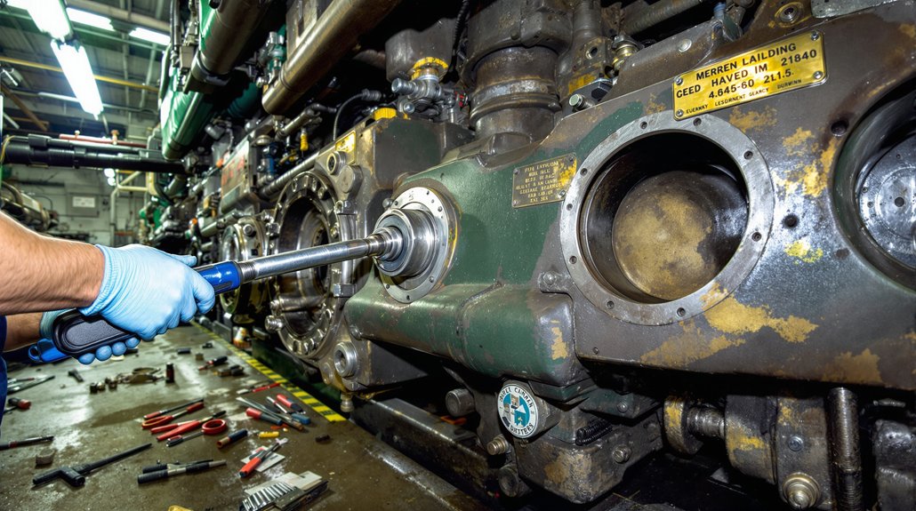
Evaluate Bearing Yield Strength

Although EMD locomotive bearings operate under extreme load and dynamic conditions, their yield strength must consistently meet or exceed rigorous AAR standards for axle and journal materials. When you evaluate bearing performance, focus on yield criteria such as the 23-ton axle load limit, 6.5″ journal diameter, and the use of high-strength alloy steels in critical components. These parameters guarantee the bearings withstand peak tractive efforts of up to 560 kN and manage significant lateral and axial forces.

EMD-exclusive crowned roller geometry and integrated thrust blocks further optimize stress distribution, reducing localized strain and maintaining structural integrity. Verify that all candidate materials meet AAR property standards through documented material testing protocols to guarantee consistent yield strength and reliable load-bearing capacity in demanding operational environments.

Analyze Fatigue Life

Because EMD locomotive bearings endure millions of loading cycles under fluctuating wheel-rail forces, you must quantify fatigue life to guarantee reliable service intervals and structural safety. Start by conducting fatigue testing under both accelerated and real-world conditions, then benchmark cycles-to-failure for each material candidate. Use Miner’s rule to calculate cumulative damage accumulation from variable load histories, and compare lab-test damage ratios—such as a 3:1 severity factor—to field data for accurate service life predictions.

Map peak operational stresses against material endurance limits, evaluating crack propagation rates and creep-fatigue interactions, especially at elevated temperatures. Integrate predictive modeling, like ILSTM networks and dynamic simulations, to estimate remaining useful life, and cross-validate results with instrumented wheelset data. This standards-driven approach guarantees ideal material selection and maintenance alignment. Because unique components exist for each model, you must also account for model-specific compatibility when analyzing bearing material fatigue and replacement intervals.

Examine Stress Distribution

How do you guarantee EMD locomotive bearings withstand the demanding interplay of mechanical and thermal loads in service? Start by analyzing stress redistribution and the primary load path for each bearing material under operational scenarios. Proper alignment guarantees even load distribution, minimizing peak stress concentrations. Under combined vertical, lateral, and thermal loading (V1+L1+TH), expect synergistic stress increases, especially at bore inner surfaces and wheel treads, where torque transmission and braking-induced gradients interact.

Select materials with high yield strength and thermal stability to handle these stress hotspots and avoid plastic deformation. Numerical modeling using the finite element method, as highlighted by recent research, provides detailed insight into the thermal and stress-strain state of locomotive components and can predict critical stress concentrations in bearing materials. Surface treatments and wear-resistant alloys further reduce microstructural degradation under cyclic stress. Rely on standardized RDSO test protocols to simulate real-world combined load cases and verify that your chosen material maintains structural integrity throughout the operational spectrum.

Analyze Lubrication Compatibility

lubricant compatibility and testing

Effective lubrication compatibility in EMD locomotive bearings depends on strict adherence to both additive chemistry and viscosity requirements outlined by OEM standards. You must conduct thorough lubrication analysis to guarantee oils contain less than 10 ppm zinc, preventing additive incompatibility with silver or lead substrates. Select only those lubricants formulated with lead-free, corrosion-resistant additives to avoid unwanted chemical reactions that can displace bearing material and obstruct lubrication channels. Maintain pH stability and moisture resistance to protect against oxidation and premature wear.

From a viscosity standpoint, always reference EMD’s prescribed grade charts. Oils that are too thin can’t sustain hydrodynamic separation, increasing steel-to-steel contact, while excessively thick oils compromise energy efficiency and may cause overheating. Compatibility testing is critical—never blend oils without manufacturer-approved mix tests, and only use API-classified lubricants to guarantee additive consistency. Prioritize standalone EMD lubricants and regularly review batch consistency to avoid costly bearing failures and unplanned downtime. The corrosive effects of high zinc oils have been documented to cause significant bearing damage in EMD engines, reinforcing the importance of verifying additive content before use.

Review Thermal Performance Characteristics

thermal management in bearings

When evaluating EMD locomotive bearing materials, you must rigorously assess their thermal performance characteristics to guarantee reliable operation under demanding traction motor environments. Effective temperature management is essential, as bearings must dissipate heat generated by both stator and rotor components. Materials with high thermal conductivity improve heat dissipation, reducing thermal gradients and minimizing hotspots that can lead to stress concentrations.

Comparing steel to advanced alloys requires a close look at conductivity levels—higher thermal conductivity enhances compatibility with air- or liquid-cooled systems and extends bearing lifespan by mitigating thermal fatigue. The Locomotive Interface Gateway (LIG) collects data from locomotive control systems, offering valuable insights into operational temperatures and fault conditions that can guide bearing material selection. Thermal expansion and repeated cycling demand materials that retain mechanical integrity and resist deformation. Proper housing design and sealing further influence heat dissipation and protect against contamination. Evaluate these performance aspects using the table below:

ParameterImpact on Bearing Performance
Thermal ConductivityImproves heat dissipation
Heat CapacityMaintains thermal stability
Stress ResistanceMinimizes thermal fatigue
Housing/Cooling DesignModulates thermal load
Thermal ExpansionPrevents deformation/failure

Check Interchangeability and Fit Across Models

verify locomotive bearing compatibility

Curiously, EMD’s approach to component standardization means you can’t assume bearings will fit interchangeably across all locomotive models without rigorous verification. To verify cross model compatibility, start by decoding part numbers—compare specific codes such as 16-567B versus 16-645E to pinpoint shared or unique bearing components. Always reference EMD’s official part catalogs and cross-check against supplier data for models like the 645F, 645E, or 645E3. Examine technical specs for tapered roller bearings, including arrangement (back-to-back or face-to-face), and validate dimensions, clearances, and load ratings per OEM criteria.

Prototype fitment tests are essential; conduct these in controlled conditions, measuring internal clearances post-installation to guarantee alignment with EMD torque specs. Also, map supplier identifiers to EMD’s numbering scheme, accounting for legacy and modern part numbers as well as regional variations. High-performance bearings and bushings are critical for smooth engine operation and reduced wear, so it’s vital to ensure that your chosen material and design match EMD’s precise engineering standards. This data-driven approach confirms you identify true interchangeability, preventing costly installation errors or premature failures.

Compare Maintenance Needs and Replacement Frequency

optimize bearing maintenance schedules

You’ll need to align lubrication schedules with the specific bearing material, as plain and rolling element bearings require different grease types and intervals per manufacturer standards. Use precision inspection tools and set wear detection intervals based on both operating hours and real-time data, such as vibration analysis. This targeted approach guarantees you optimize replacement frequency and reduce unplanned downtime.

Lubrication Schedules by Material

A well-structured lubrication schedule is crucial for maximizing the service life of EMD locomotive bearings, and the maintenance approach varies considerably by bearing material. For plain (journal) bearings, you’ll need to select high-quality lubricant types and follow manufacturer-recommended intervals, as these bearings are sensitive to lubricant viscosity and over-lubrication.

Inspection techniques such as scheduled visual checks and grease sampling are essential to guarantee ideal lubricant condition. Rolling element bearings, including ball and cylindrical types, require tailored grease or oil intervals based on load and speed, with maintenance cycles often differing by bearing configuration. Proper lubrication and maintenance help reduce friction in locomotive bearings, which is critical for the efficient function of the traction motor. Thrust bearings demand precise oil flow schedules to manage axial loads efficiently. Material selection, operating conditions, and inspection frequency all influence your lubrication and replacement strategies.

Wear Detection and Intervals

Beyond optimizing lubrication schedules, effective wear detection directly impacts maintenance intervals and the longevity of EMD locomotive bearings—particularly as monitoring technologies advance and bearing materials diversify. You’ll want to leverage vibration monitoring and advanced signal decomposition for real-time analysis of wear patterns, enabling early fault classification and predictive maintenance. EEMD and wavelet-packet methods deliver robust performance comparison, overcoming noise interference and material fatigue challenges.

Combine inspection techniques—visual checks, dimensional measurements, and ultrasonic analysis—for thorough diagnostics. Predictive intervals should reflect baseline vibration profiles, material-specific fatigue, and OEM recommendations. Additionally, since bearing faults account for 30% to 40% of failures in rotating electric machines, prioritizing early detection and accurate interval prediction is critical for operational reliability. The table below summarizes key approaches:

MethodStrengthsTypical Use Case
FFT AnalysisBroad wear pattern IDRoutine monitoring
EEMDNoise robustnessMulti-fault environments
Wavelet-PacketFault classificationEarly-stage defect detection
Visual InspectionSurface defect detectionScheduled maintenance
Ultrasonic TestingInternal flaw discoveryPost-disassembly assessment

Investigate Wear Resistance and Fatigue Life

material performance trade offs analyzed

While bearing material selection directly influences both wear resistance and fatigue life in EMD locomotives, each material presents distinct performance trade-offs under operational loads and speeds. You must analyze wear mechanisms and fatigue patterns to determine ideal material choices. Ball bearings excel in high-speed scenarios, resisting surface wear and demonstrating prolonged fatigue life, but may not tolerate heavy shock loads. Stainless steel bearings withstand extreme stresses and high RPMs, though their increased weight impacts fuel efficiency.

Bronze alloys offer custom strength profiles but suffer accelerated wear without consistent lubrication, impacting long-term performance. Cast iron bearings minimize friction due to self-glazing, yet their wear mechanisms are load-dependent. Silver-and-lead bearings display rapid fatigue when oil channels clog—material displacement leads to catastrophic failure modes. Rubber bushings in EMD traction motors show superior fatigue resistance, achieving over a million miles with minimal wear. Regular evaluation of material properties and maintenance can help prevent failures and extend the service life of bearings in demanding locomotive environments. Quantitative fatigue testing and routine inspection, per industry standards, remain essential for reliability.

Examine Chemical and Corrosion Resistance

chemical and corrosion resistance evaluation

Because EMD locomotive bearings routinely encounter aggressive chemicals, corrosive environments, and fluctuating thermal loads, material selection must emphasize both chemical stability and corrosion resistance. You need to evaluate how candidate materials handle exposure to EMD-specific lubricants, hydraulic fluids, and chemical byproducts like nitrogen oxides and sulfur compounds. In humid, marine, or mining settings, prioritize alloys with proven chemical resistance and built-in corrosion prevention mechanisms, such as passivation layers or advanced surface coatings. Choose materials that resist pitting, surface degradation, and electrolysis, especially where saltwater or condensation is prevalent.

Here’s a comparative snapshot:

MaterialChemical ResistanceCorrosion Prevention
52100 Bearing SteelModerateRequires coatings
Stainless SteelHigh (316L, 440C)Inherent passivation
Bronze AlloysGood (with tin)Needs regular lubrication
Ceramic HybridsExcellentNaturally inert
Coated SteelsVariable (by coating)Dependent on application

Optimize your selection by referencing actual corrosion test data and EMD operating standards.

Consider Cost-Effectiveness and Service Life

cost effectiveness and longevity considerations

You need to weigh initial material costs against projected service life, as higher-priced alloys like high-carbon steel can lower long-term expenses through reduced replacements. Maintenance frequency directly impacts cost-effectiveness, especially when extended lubrication intervals or predictive programs reduce downtime. Replacement cycles and overall longevity should align with operational standards to optimize lifecycle value and meet reliability targets.

Balancing Price and Durability

Selecting bearing materials for EMD locomotives requires a careful assessment of both procurement cost and service life, as these factors directly impact total cost of ownership. You should conduct a cost benefit analysis that weighs the initial price against expected durability. For example, bainitic steel alloys offer superior tensile strength (180-200 ksi) but cost 15-25% more than standard carbon steel.

Carburized materials provide high surface hardness (Rockwell C 50+) with core toughness for cyclic loading, justifying their higher upfront expense in demanding applications. When evaluating performance trade offs, consider that sintered metal bearings reduce weight by 20% for non-critical uses, while premium coatings like nickel/chromium or remelted tungsten carbide address corrosion and extreme loads. Data-driven selection guarantees the best balance between price and longevity.

Maintenance Frequency Impacts Cost

Although premium bearing materials contribute to longer service life, maintenance frequency remains a primary driver of overall cost-effectiveness in EMD locomotive operations. Effective maintenance scheduling directly impacts both labor and material expenditures. By leveraging data-driven maintenance logs and predictive strategies, you can optimize service intervals to minimize unnecessary downtime and reduce total lifecycle costs. Cost analysis shows that routine inspections and fluid checks prevent expensive failures and prolong bearing service life, ensuring resource allocation aligns with operational standards.

Key points to reflect on:

  1. Routine lubrication and weekly fluid checks extend bearing life and prevent accelerated wear.
  2. Predictive monitoring (vibration and lubricant analysis) supports on-condition maintenance, reducing premature replacements.
  3. Optimized maintenance scheduling—including overlapping tasks—lowers labor costs and aligns with vendor-recommended intervals for cost-effective operation.

Replacement Cycles and Longevity

Optimizing maintenance intervals is only part of maximizing cost-effectiveness; the inherent replacement cycles and lifespan of EMD locomotive bearing materials must also be considered. When you evaluate bearing options, focus on replacement frequency and bearing compatibility with your locomotive’s operational demands.

Plain bearings, while simple and cost-effective initially, often require more frequent overhauls due to higher friction and wear, raising long-term expenses. In contrast, cylindrical roller bearings like the NSK JT series use high-carbon steel and standardized dimensions, reducing both replacement frequency and inventory costs through improved bearing compatibility and interchangeability. Cam and turbocharger bearings experience high stress and environmental exposure, demanding vigilant monitoring and sometimes earlier replacement. Ultimately, prioritizing bearings with extended service life and predictable replacement cycles enhances reliability and total lifecycle value for EMD fleets.

Inspect Surface Finish and Hardness Consistency

surface finish and hardness

When inspecting EMD locomotive bearing materials, you must verify that surface finishes meet specified roughness (Ra) values to confirm efficient oil flow and prevent lubrication channel blockages. Even minor surface imperfections, often invisible to the naked eye, can obstruct lubrication channels and compromise performance. Use microscopic analysis to detect these imperfections and confirm commutator surfaces are smooth, which reduces brush wear and material debris. Measuring surface roughness provides quantitative assurance that bearing surfaces are within tolerance.

Additionally, assess hardness consistency across the bearing material. Variations can indicate improper heat treatment or material degradation. Silver concentration thresholds (≤1 ppm normal, >2 ppm critical) serve as quantitative indicators for underlying wear or contamination.

To confirm reliability:

  1. Conduct microscopic analysis for surface imperfections and debris.
  2. Measure Ra values and compare against engineering specifications.
  3. Verify hardness levels across multiple points to detect inconsistencies.

Frequently Asked Questions

How Do Bearing Materials Impact Locomotive Noise and Vibration?

When you select bearing materials, you directly influence bearing performance and noise reduction in locomotives. High-strength alloys support greater loads, minimizing stress-induced vibration. Materials with high damping coefficients absorb vibration energy, converting it to heat and lowering noise. Low-friction surfaces and proper lubricant compatibility further reduce friction-induced noise. Choosing materials with strong defect resistance and stable thermal expansion guarantees alignment, preventing vibration spikes and maintaining consistent noise reduction throughout the bearing’s operational life.

Are Eco-Friendly Bearing Materials Available for EMD Locomotives?

Did you know recycled steel alloys can cut raw material use by up to 40% in bearing casings? You’ve got sustainable materials emerging for EMD locomotives, like ceramic-coated bearings and hybrids with non-toxic additives. These options lower environmental impact while meeting industry standards for strength, corrosion resistance, and heat dissipation. Still, mainstream adoption is limited, so you’ll need to validate eco-friendly solutions through lifecycle assessments and guarantee full compatibility with EMD legacy systems.

What Certifications Should EMD Bearing Materials Meet?

When selecting EMD bearing materials, you need to guarantee they meet strict certification standards for ideal bearing quality. Require ISO 9001 certification for supplier quality systems and IATF 16949 for automotive components. Confirm compliance with AAR specifications and 49 CFR Part 229 for regulatory safety. Don’t overlook documented traceability of all certifications and demand regular supplier audits. These standards assure the bearing materials perform reliably in demanding locomotive environments.

Can Aftermarket Bearings Void Locomotive Warranties?

You need to evaluate warranty implications and aftermarket risks before installing non-OEM bearings. Federal law says a manufacturer can’t void your warranty just for using aftermarket parts, but they can deny claims if they prove a direct link between the bearing and failure. If improper installation or material incompatibility causes damage, you risk losing warranty coverage. Always document installations and use certified professionals to minimize the chance of warranty issues related to aftermarket bearings.
How Quickly Can Different Bearing Materials Be Sourced?

Wondering how supply chain efficiency affects your bearing replacement plans? You’ll get standard materials like bronze or steel shipped within days, thanks to strong material availability and global supplier networks. If you need specialty alloys or custom-bored steel bearings, expect a 4-6 week lead time because of production and certification requirements. Off-the-shelf parts minimize downtime, but compliance with ISO or IATF standards can add processing days, especially for exotic or legacy components.

Types of Connecting Rod Bearings in EMD Locomotives

Types of Connecting Rod Bearings in EMD Locomotives

When you work with EMD locomotives, you’ll encounter connecting rod bearings like ball bearings for precision and durability, cartridge-type tapered roller bearings for handling intense radial and axial loads, and plain journal bearings that rely on hydrodynamic lubrication for high-stress reliability. You’ll also use undersized or hardened steel-backed shells for precise clearance and load control. Each type serves a distinct function in load management and longevity. The specifics of installation and maintenance can get quite intricate as you explore further.

Key Takeaways

  • EMD locomotives use ball bearings, roller bearings, and plain (sleeve-type) bearings in connecting rod assemblies.
  • Ball bearings in connecting rods are typically sealed, chromium-coated, and designed for durability and reduced friction.
  • Roller bearings, often of the tapered cartridge type, provide high load capacity and maintain precise alignment under heavy traction forces.
  • Plain bearings use a continuous oil film for friction reduction and are highly sensitive to lubricant quality.
  • Bearing selection includes standard and undersized options, with precise OEM tolerances ensuring proper fit and load distribution.

Ball Bearings: Features and Applications

durable efficient locomotive components

Ball bearings serve as critical components in EMD locomotive connecting rod assemblies, where their advanced material compositions and engineered designs address the demanding operational environment. When you select ball bearings for this application, you’ll encounter ball bearing materials like chromium-coated steel alloys, which provide enhanced durability and wear resistance in high-stress, high-speed conditions. Vacuum degassed materials guarantee internal cleanliness, minimizing contamination and extending service life. Application advantages include multiple-row configurations that deliver high load capacities within restricted spatial envelopes, while thrust-loaded designs efficiently support axial stresses from reciprocating connecting rods.

Specialized cage structures minimize friction and promote consistent lubrication, reducing thermal buildup and guaranteeing sustained high-RPM performance. Surface treatments such as black oxiding offer critical corrosion resistance, valuable in locomotive engine compartments. Sealed and pre-packed designs retain lubricants, lowering maintenance intervals and enhancing reliability. With these features, you’re maximizing operational uptime and guaranteeing precise, vibration-resistant operation in EMD locomotive engines. Ball bearings are known for their durability and efficiency in high-speed locomotives, making them especially suitable for the rigorous demands of EMD connecting rod applications.

Roller Bearings: Heavy-Duty Performance

heavy duty roller bearing performance

Roller bearing assemblies deliver the heavy-duty performance essential for EMD locomotive connecting rod applications, where extreme load demands and dynamic stresses are routine. When you select roller bearing applications, focus on cartridge-type tapered roller bearings, such as Timken’s, which notably increase load capacity and minimize friction at the pin and crank interfaces. Tapered roller benefits include optimized load distribution between inner and outer races, ensuring both axial and radial alignment even under severe traction forces. NSK’s vacuum-degassed materials further enhance fatigue resistance, vital for continuous high-stress operation.

You’ll find industry-standard dimensions—typically 120–250 mm for JT models—provide interchangeability across EMD locomotive platforms. Mikura International, ensuring customers have access to reliable components that meet or exceed OEM standards. Electrical insulation specifications (≥2000MΩ) prevent arcing, while sealed environments and ceramic-coated options combat contamination and enable short-term, lubricant-free operation under thermal extremes. High-precision machining and M16–M20 cap screw mounting secure roller bearings in high-torque assemblies, supporting intense axle weights and dynamic cargo stresses common in freight and passenger service.

Plain Bearings: Simplicity and Limitations

plain bearings require lubrication

You’ll notice that plain bearings use a basic sleeve-type design, relying on a continuous film of lubricant to minimize friction and surface wear. This simplicity reduces the number of moving parts but makes these bearings highly sensitive to lubrication quality and prone to rapid degradation if oil supply is interrupted. In EMD locomotives, you typically find them in auxiliary systems where load demands are moderate and consistent lubrication can be maintained. Material selection for plain bearings is crucial, as using high-quality alloys or composites can significantly enhance their resistance to wear and their overall lifespan.

Basic Sleeve-Type Design

While more complex bearing types exist, the basic sleeve-type (plain) bearing remains a fundamental component in EMD locomotive engines due to its mechanical simplicity and reliability. You’ll find sleeve advantages in their minimal part count—just a shaft-mounted journal and a fixed cylindrical sleeve—which reduces failure points and manufacturing complexity. These plain bearings handle both axial and radial loads through optimized contact surfaces, making them suitable for connecting rod and crankshaft applications.

Material choices are critical; bimetallic constructions, such as steel-backed shells with babbitt or polymer liners, balance wear resistance, low friction, and cost. Selected materials also address thermal expansion and corrosion, ensuring long service life. However, sleeve-type designs lack rolling elements and rely solely on sliding surfaces, setting inherent limits on load capacity. One important factor to consider is that lubrication methods are essential to reduce friction and prevent excessive wear, as plain bearings depend entirely on a film of lubricant to separate the moving surfaces.

Lubrication and Wear Issues

Although plain bearings in EMD locomotive connecting rods offer mechanical simplicity, their performance hinges on meticulous lubrication control and careful wear management. You’ll face significant lubrication challenges, including the necessity to use OEM-specified SAE 40 oil and to maintain ideal oil capacity—typically 15-20% charge—to prevent overheating and excessive pressure. Blocked oil channels, often from displaced silver/lead bearing material, can cause lubrication deprivation failures.

For EMD locomotive oil qualification, the Silver Lubricity Test is conducted under precise temperature and speed conditions using a research engine to ensure the lubricant’s effectiveness in protecting plain bearings. Wear mechanisms such as substrate extrusion and friction-induced overheating arise when the lubricant film breaks down, especially during cold starts or high-heat operation. Monitor for silver concentration spikes in lube oil, as they indicate active bearing wear. Material incompatibility and cyclic load stress further accelerate micro-cracking. Consistent oil analysis and adherence to torque and clearance standards are essential for reliable performance.

Application in Auxiliary Systems

Managing lubrication and wear in connecting rod bearings sets a baseline for understanding how plain bearings function in EMD locomotive auxiliary systems, where demands differ yet mechanical simplicity remains a priority. In auxiliary applications, you’ll find plain bearings excel due to their passive operation and ease of integration, especially when weight-centric design limits are observed. These bearings favor linear load transmission and are engineered for modular bearing integration—key for fuel manifolds or electric circuits. However, their use is restricted in high-torque or heavy-duty environments.

  • Interchangeable sizing allows seamless upgrades to .093″ oversize sleeves for worn components.
  • Redundant integration across auxiliary systems guarantees uniform load distribution.
  • Minimal sensor requirements simplify maintenance and diagnostics.
  • Spring steel pedestal pairing enhances stability for vibration-prone subsystems.
  • Some parts are interchangeable across different EMD models, which can simplify maintenance and reduce locomotive downtime in auxiliary systems.

Recognize their operational simplicity, but always consider their inherent limitations.

Journal Bearings: Reliability in EMD Engines

journal bearings enhance reliability

Reliability defines the role of journal bearings in EMD locomotive engines, where plain (journal-type) bearings outperform alternatives in high-stress environments. When you conduct a performance analysis, you’ll see that the high surface area of journal bearings distributes loads effectively, minimizing localized stress. This design, combined with precision-ground surfaces, enhances wear resistance and supports long service life. The sliding surfaces, paired with a robust forced oil feed, create a hydrodynamic lubrication layer that prevents metal-to-metal contact, drastically reducing wear and maintenance frequency.

You benefit from built-in wear compensation via wiper strips, which allow the bearing to self-adjust and maintain ideal clearance over time. Integration with primary lubrication systems ensures efficient heat dissipation, further protecting against thermal degradation. Cartridge-type assemblies simplify replacement and alignment, minimizing downtime. Regular inspections, oil sample analysis, and strict contamination control during servicing are essential to maintain reliability and prevent premature failures. This approach maximizes uptime and operational efficiency.

Tapered Roller Bearings: Alignment and Load Handling

precision load alignment management

When you’re working with tapered roller bearings in EMD locomotives, you need to address angular contact load management to guarantee both radial and axial forces are properly absorbed. You’ll also have to account for shaft misalignment correction, as even minor deviations can accelerate wear or induce vibration. Precision alignment adjustments, often achieved through calibrated shimming, are essential for ideal load distribution and extended service life.

Angular Contact Load Management

Although EMD locomotives generate substantial multi-directional forces within their power assemblies, tapered roller bearings excel at angular contact load management by leveraging their unique geometry. With an angular contact design, these bearings handle combined radial and axial loads seamlessly, distributing forces efficiently across the roller-raceway interface.

Converging contact angles control load distribution, keeping stress centralized and reducing localized wear. The crown-shaped rollers further prevent edge stress, supporting high-precision alignment and ideal load transfer under dynamic diesel engine conditions. You’ll find that their hardened, heat-resistant alloys maintain dimensional stability, even during prolonged high-load operation. Mikura International, an ISO Certified company, ensures that these engineered bearings consistently meet or exceed OEM specifications for reliability in demanding rail service.

  • Angular contact design guarantees precise radial and axial load management
  • Converging contact angles enhance force distribution along the bearing
  • Crown-shaped rollers mitigate edge stress and enhance durability
  • Heat-resistant, wear-resistant alloys enable long service life in harsh environments

Shaft Misalignment Correction

Even slight shaft misalignment in EMD locomotive power assemblies can disrupt force equilibrium, accelerating bearing fatigue and risking catastrophic failure. To address this, you must employ precise shaft alignment techniques during tapered roller bearing installation. Use pilot sleeves to guide the bearings onto axles, ensuring concentric alignment and minimizing the risk of uneven load distribution.

Adjustment tools are essential for achieving the correct seating tonnage—typically 30–40 short tons for B-class bearings—and for setting precise internal clearance. Dial indicators can read in thousandths of an inch, making them invaluable for verifying alignment accuracy during installation. After installation, always perform rotation checks to confirm smooth movement and proper contact with axle fillets. Neglecting these steps can overload the bearing’s internal ring rib or compromise the back-to-back arrangement’s ability to handle combined radial-axial loads, leading to premature wear and costly repairs.

Precision Alignment Adjustments

Proper precision alignment adjustments are critical for guaranteeing tapered roller bearings in EMD locomotives can handle demanding load profiles without premature wear. You need to use alignment tools and precision measurements to achieve ideal load distribution and prevent axial preload deviations. Pilot sleeves keep cone spacers aligned during assembly, while mechanical seating tonnage (30–40 tons) guarantees full bearing contact with the axle fillet. Internal clearance must be set precisely; too little or too much clearance increases friction and reduces bearing life. Post-assembly, verify rotation to confirm no binding or interference, confirming your adjustments are effective. For large machines, using gauge indicators on coupling faces is a recommended measurement technique to accurately assess alignment before finalizing bearing installation.

  • Use pilot sleeves for precise cone alignment during installation
  • Apply correct seating tonnage for stable compression
  • Rely on torque specs and precision measurements for cap screws
  • Verify rotational freedom after assembly to detect misalignment

Fork-and-Blade Design Bearing Considerations

bearing stability and lubrication

When evaluating the fork-and-blade connecting rod arrangement in EMD locomotives, you’ll need to account for unique bearing considerations dictated by its interlocking geometry and high-load dynamics. The fork blade interaction inherently governs bearing stability, as the master (fork) rod must securely house bearing inserts capable of handling intense compression and reciprocating forces. Meanwhile, the blade rod’s counterbored fit into the fork rod stabilizes the assembly, denying unwanted longitudinal movement and maintaining precise alignment.

Material selection is critical—steel-backed lead bronze shells with lead-tin coatings are used to balance strength, wear resistance, and friction reduction. Specialized bearing sleeves and counterweighted crankshafts ensure smooth operation and optimal weight distribution in these high-performance assemblies. Proper lubrication is guaranteed via crankshaft-drilled passages and oil-retaining thumbprints in thrust collars, which protect against overheating.

Here’s a quick comparison of key aspects:

FeatureBearing Consideration
Fork Blade InteractionProvides structural stability and alignment
Material SelectionEnhances load capacity and wear resistance
Lubrication ApproachMaintains film integrity under high loads
Thrust CollarsDistribute thrust and retain lubricant

Undersized Bearings and Precision Fitment

precision undersized bearing fitment

Precision dictates every aspect of undersized bearing selection and fitment in EMD locomotive engines. When you’re performing underground maintenance or rebuilding an EMD power assembly, you’ll encounter crankshaft journals reground to specific undersize increments—typically 0.010″, 0.020″, or 0.030″. Selecting the correct undersized bearing guarantees ideal clearance and load distribution during bearing installation. EMD-specific tolerances demand exact dimensions, often checked with feeler gauges or micrometers. Hardened steel-backed designs, such as Clevite H-Series bearings, provide the necessary interference fit and high crush force, maintaining alignment even under severe operating stress.

  • Mix standard and undersized shells for half-thousandth clearance adjustments
  • Choose bushings or sleeves when additional load support is needed
  • Confirm bearing compatibility with EMD crankshaft steel grades and journal radii
  • Rely on serial number matching for precise fitment to specific engine models

Undersized bearings, when properly installed, extend crankshaft life and restore ideal engine geometry.

Maintenance Practices for Connecting Rod Bearings

connecting rod bearing maintenance

Although connecting rod bearings are engineered for durability in EMD locomotives, meticulous maintenance practices remain essential to maximize service life and prevent catastrophic engine failures. You should begin inspection procedures by loosening the main bearing stud nuts—this supports the bearing while allowing thorough evaluation. Examine wear patterns, verifying bearings are matched to their cap bore orientation for positional accuracy. Utilize Plastigage strips to measure clearance between the bearing inserts and crankshaft journals, confirming tolerances are within EMD specifications. Check for overheating signs—such as discoloration or indentations—and address fretting by cleaning raised material in the cap bore and bearing back.

For replacement protocol, always pre-fit connecting rods to the crankshaft, verify alignment, and clean journals before installing new bearings. Use only manufacturer-approved alloys and reject components with surface defects. Document every replacement, adhering to EMD service intervals. Post-installation, measure clearances again, validate alignment, and pressure-test lubrication galleries to guarantee operational integrity.

Frequently Asked Questions

What Materials Are Commonly Used to Manufacture Connecting Rod Bearings?

Picture a bearing’s heart made of bronze alloys, beating with strength and precision in harsh environments. When you select materials for connecting rod bearings, you’ll often rely on bronze alloys for their superb load-carrying capacity and wear resistance. Polymer composites enter the scene for reduced friction and weight, ideal in modern, high-efficiency engines. Your choices hinge on balancing thermal stability, fatigue resistance, and lubrication compatibility to guarantee peak long-term engine reliability.

How Does Bearing Selection Affect Overall Locomotive Fuel Efficiency?

When you select the right bearing design, you directly impact fuel economy by minimizing friction losses and parasitic energy drain. You should analyze load handling, lubrication requirements, and material properties—ball and roller bearings typically reduce friction, while plain bearings may increase it over time. If you choose bearings with ideal surface quality and proper lubrication, you’ll maintain consistent efficiency, cut unnecessary fuel consumption, and extend maintenance intervals, resulting in measurable operational cost savings.

Are There Any Common Signs of Impending Connecting Rod Bearing Failure?

Think of your engine as a symphony—when connecting rod bearings fail, the harmony falters. You’ll notice increased vibration during vibration analysis, drops in oil pressure, and metallic knocking or grinding sounds. Watch for contaminated oil with metal particles and irregular oil levels. Performance dips, rough operation, and blue exhaust smoke also signal trouble. Visual inspections may reveal worn bearing surfaces, scoring, or embedded debris, all pointing to impending bearing failure.

What Are the Environmental Impacts of Bearing Lubricant Disposal?

When you improperly dispose of used lubricant, you cause significant lubricant contamination in water, soil, and air. Even small amounts can pollute vast water supplies, disrupt aquatic ecosystems, and bioaccumulate toxins up the food chain. Volatile organic compounds released during disposal degrade air quality, while hydrocarbons impair soil health. Without strict disposal regulations and recycling, improper disposal methods like burning or dumping exacerbate environmental harm and pose severe long-term health risks to humans and wildlife.

Can Aftermarket Bearings Be Used Without Voiding EMD Engine Warranties?

You might assume aftermarket compatibility guarantees seamless installation, but warranty implications tell a different story. If you use aftermarket bearings that don’t precisely match EMD’s OEM specifications for material, tolerances, and documentation, you risk voiding your engine warranty. EMD’s strict protocols require certified part numbers and material validation; even minor deviations or improper fitting can result in denied claims. Always verify full compliance with EMD standards to maintain your warranty coverage.

7 Tips: Maximizing EMD Locomotive Diode Efficiency

7 Tips: Maximizing EMD Locomotive Diode Efficiency

To maximize your EMD locomotive diode efficiency, implement real-time voltage and current monitoring to maintain tight control and detect anomalies early. Enhance regenerative braking to reduce thermal stress and manage power flow effectively. Use modular power electronics for fault isolation and apply advanced cooling systems like liquid-cooled modules to dissipate heat efficiently. Integrate feedback loops in power circuits and employ predictive maintenance to extend diode lifespan. Also, train operators on efficient control strategies to enhance overall system reliability. Further insights reveal how these techniques interconnect for peak performance.
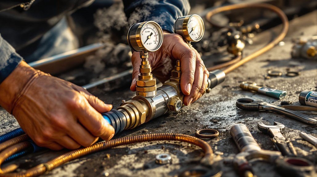
Key Takeaways

  • Implement real-time voltage and current monitoring to maintain diode operation within safe thresholds and prevent overload.
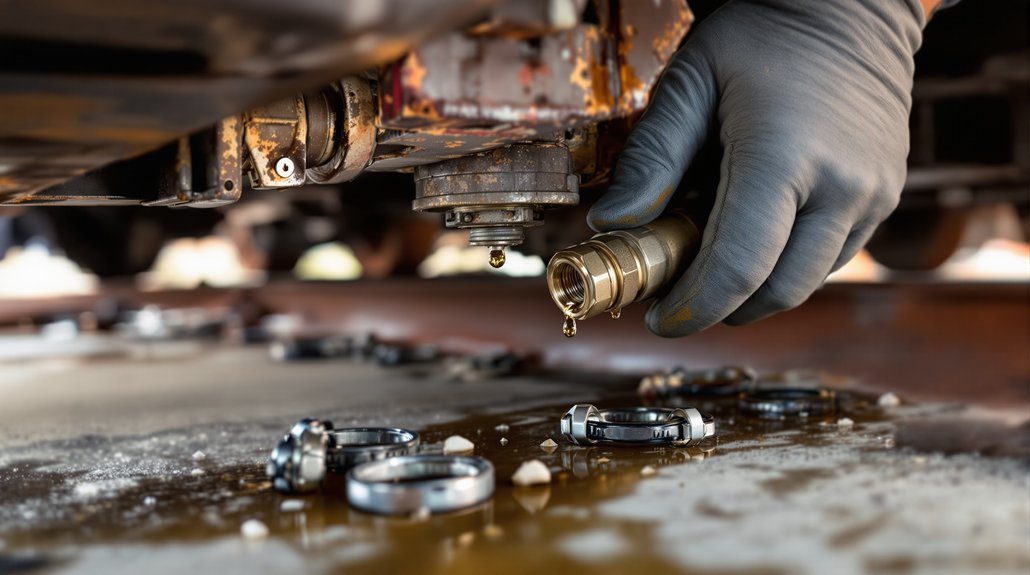
  • Use forced-air or liquid cooling systems combined with thermal sensors to effectively dissipate heat from diode modules.
  • Integrate adaptive feedback loops to regulate output voltage dynamically, optimizing diode efficiency under varying load conditions.
  • Employ surge protection clamps and circuit breakers to isolate faults quickly and protect diode junctions from transient spikes.
  • Schedule predictive maintenance using AI-driven anomaly detection to identify early signs of diode degradation and prevent failures.

Implement Real-Time Voltage and Current Monitoring

real time electrical parameter monitoring

When you implement real-time voltage and current monitoring, you gain precise control over your EMD locomotive’s diode efficiency by continuously tracking electrical parameters within tight ±1V thresholds. Utilizing IGBT-based systems, you regulate voltage across the 1,500–25,000V range with high accuracy. Real time analytics platforms, such as Progress Rail’s LIG, provide centralized monitoring of voltage, current, and fault data, enabling immediate detection of deviations beyond preset thresholds. You can configure remote portals to display live readings and adjust sensor thresholds dynamically via over-the-air updates, guaranteeing responsiveness to operating conditions.

Incorporating current transducer arrays enhances fault detection by monitoring traction motor loading, while automated protective responses prevent damage under overload scenarios. Prioritizing Ethernet and serial protocols ensures high-speed data transmission critical for real-time feedback loops. Effective thermal management is essential to maintain component longevity and prevent overheating during high-voltage operations. By standardizing voltage thresholds and integrating continuous data capture, you optimize diode performance, maintain system integrity, and reduce thermal stress, all while enabling proactive maintenance decisions grounded in precise electrical parameter control.

Optimize Regenerative Braking to Reduce Thermal Stress

optimize energy capture efficiency

To optimize regenerative braking and reduce thermal stress, you must enhance energy capture through advanced storage and efficient diode components. Managing heat dissipation is critical, requiring precise thermal controls and improved cooling systems to maintain diode integrity. Finally, balancing power output across braking phases prevents localized overheating and maximizes overall system efficiency.

Enhance Energy Capture

Although regenerative braking offers substantial energy recovery, optimizing its efficiency is essential to reducing thermal stress on locomotive components. You can enhance energy capture by integrating advanced energy management systems (EMS) that maximize kinetic energy conversion during deceleration, targeting efficiency metrics close to 99.8%. Prioritize energy storage solutions capable of rapidly absorbing and redistributing recovered power to prevent bottlenecks and minimize loss.

Employ real-time monitoring to adjust braking intensity based on speed and gradient factors, ensuring maximum energy retention without overloading the system. By aligning regenerative outputs with grid demand and storage capacity, you reduce reliance on resistive dissipation, directly lowering thermal stress. This precise control improves overall energy utilization, extends component lifespan, and supports sustainable operation while maintaining peak diode efficiency in EMD locomotives. Additionally, selecting Lithium Titanium Oxide (LTO) batteries for onboard energy storage has been shown to provide significant net present value benefits while offering reliable and efficient energy recovery in diesel-electric freight trains.

Manage Heat Dissipation

Maximizing energy capture through advanced EMS and real-time control naturally demands effective heat dissipation strategies to protect diode integrity during regenerative braking. You must monitor diode temperatures with high-frequency thermal sensors and use threshold alerts to reduce braking torque when heat transfer risks exceed safe limits. Employ forced-air or liquid cooling systems combined with modular heat sinks made of high thermal conductivity materials to disperse heat efficiently.

Integrate thermal insulation selectively to shield sensitive components without impeding necessary heat flow. Optimize regenerative braking parameters via dynamic resistance tuning and predictive algorithms to balance energy recovery and thermal stress. Automated thermal imaging and logging help identify hotspots and schedule maintenance before damage occurs. By controlling heat transfer and managing thermal insulation, you reduce thermal stress and extend diode lifespan. Additionally, implementing advanced sensors for real-time tracking ensures continuous temperature monitoring to maintain ideal operating ranges and prevent energy recovery losses.

Balance Power Output

When you balance power output during regenerative braking, you directly reduce thermal stress on EMD locomotive diodes and associated components. To achieve this, optimize the power factor by phase-aligning regenerative current with traction circuit demands, minimizing energy harmonics that exacerbate thermal loading. Implement advanced sensors and real-time algorithms to adjust braking force dynamically, limiting variable current based on speed and load. Incorporate supercapacitors for immediate energy storage, reducing surge impacts and smoothing power delivery.

This approach is similar to how modern hybrid and electric vehicles utilize regenerative braking to extend battery range by efficiently managing energy flow and storage regenerative braking. Coordinate regenerative efforts with substations or neighboring trains to redistribute energy efficiently, preventing excessive diode heating. Additionally, regulate voltage through bidirectional inverters to maintain stable power flow. By integrating these strategies, you enhance diode longevity, improve energy recovery rates, and maintain system stability under varying operational conditions.

Utilize Modular Power Electronics for Fault Isolation

modular power electronics reliability

Because fault isolation is critical to maintaining locomotive power system reliability, modular power electronics play a pivotal role in containing failures without cascading effects. By employing modular designs with isolated thermal baseplates, you prevent thermal cross-talk between rectifiers and diodes, enhancing thermal management and component isolation. This approach considerably boosts fault tolerance by localizing failures within discrete modules, facilitating rapid isolation and minimizing downtime.

Maintenance efficiency improves through standardized drop-in replacements and calibration-free modular upgrades, enabling swift service without extensive recalibration. Enclosed high-voltage packages reinforce electrical safety by preventing arcing and interference. Together, these practices guarantee optimized load sharing and electrical protection, empowering you to sustain peak diode efficiency while safeguarding locomotive power electronics against fault propagation and thermal stress.

Apply Advanced Cooling Systems for Diode Protection

advanced diode cooling solutions

Although diode efficiency depends heavily on electrical design, advanced cooling systems play an equally critical role in protecting these components from thermal stress and premature failure. You must leverage cooling innovations that optimize thermal efficiency, ensuring diode longevity and consistent performance. Liquid-cooled diode modules directly transfer heat to coolant, preventing hotspots, while multi-stage radiator sections enhance heat exchange via parallel flow paths. Additionally, phase-change materials stabilize diode temperatures during transient loads, smoothing thermal fluctuations that otherwise degrade diode reliability. The cooling system’s centrifugal gear-driven pumps are essential for maintaining steady coolant flow, which is vital to effective heat removal from diode modules.

Key strategies to apply include:

  • Employing centrifugal gear-driven pumps with pressure-optimized flow paths to deliver uniform coolant distribution around diode modules.
  • Integrating high-conductivity heat sinks aligned with electric fan coordination for precise airflow targeting diode heat dissipation.
  • Implementing predictive maintenance using laser thermography and real-time data logging to detect thermal anomalies early and avoid cooling system failures.

Integrate Feedback Loops in Power Conversion Circuits

dynamic voltage adjustment mechanisms

You need to implement feedback loops that dynamically adjust output voltage in real time to respond to varying load conditions. This precise load-responsive control not only stabilizes power delivery but also enhances diode protection by preventing voltage spikes. By integrating such adaptive mechanisms, you optimize efficiency and safeguard critical components within the EMD locomotive power system. High output current converters often improve efficiency by replacing diodes with FETs in synchronous rectification, reducing losses in the power stage switching efficiency.

Dynamic Output Adjustment

When integrating feedback loops in power conversion circuits, dynamically adjusting the output voltage enhances both efficiency and adaptability. You can leverage dynamic feedback techniques like DAC injection or PWM-controlled voltage shifting to finely regulate voltage levels in real time. This dynamic output adjustment guarantees precise voltage regulation, minimizing power loss and optimizing diode performance under varying loads.

Key implementation considerations include:

  • Selecting precision DACs and optimizing resistor values (R_ADJ) to maintain accuracy and minimize noise. The LTC7106 DAC, for example, offers excellent current output accuracy over a wide temperature range, ensuring stable voltage adjustments.
  • Managing voltage slew rates with stepwise voltage increments to prevent triggering protection circuits.
  • Incorporating low-pass RC filters to suppress switching noise in PWM-generated adjustment signals.

Load-Responsive Voltage Control

Since load conditions can change rapidly, integrating load-responsive voltage control through feedback loops is crucial for maintaining ideal diode efficiency in EMD locomotives. You must implement precise control strategies that monitor load voltage in real-time, adjusting outputs to minimize transient deviations and optimize power delivery. Distributed power architectures with point-of-load converters improve transient response by localizing voltage regulation. Incorporate differential sensing and carefully matched components to guarantee feedback accuracy and stability.

ParameterControl StrategyImpact on Efficiency
Load Voltage VariationReal-time feedback compensationMinimizes voltage overshoot
Transient ResponseActive damping & PoL convertersStabilizes diode operation
Component Matching0.1% tolerance resistorsGuarantees precise feedback
Switching FrequencyAdaptive control algorithmsReduces switching losses

Diode Protection Mechanisms

Effective diode protection mechanisms hinge on integrating real-time feedback loops within power conversion circuits to safeguard against electrical and thermal stresses. You must monitor voltage and current continuously to detect conditions that precipitate diode failure, guaranteeing immediate intervention. Surge protection plays a critical role by clamping transient voltage spikes before they damage diode junctions. Combining automated fault responses with thermal management optimizes diode reliability and longevity.

Key strategies include:

  • Voltage/Current Surveillance: Enables early detection of anomalies triggering protective actions.
  • Circuit Breaker Activation: Rapidly isolates faulty sections to prevent cascading failures.
  • Thermal Monitoring and Cut-offs: Maintains diode operation within safe temperature thresholds.

Implementing these feedback-integrated protections guarantees robust diode performance under dynamic locomotive power demands.

Deploy Predictive Maintenance Algorithms for Diode Health

predictive diode health maintenance

Predictive maintenance algorithms harness real-time sensor data and machine learning models to identify early signs of diode degradation in EMD locomotives. By integrating multi-sensor inputs—temperature, vibration, and electrical metrics—you can track diode health with precision. Employ AI-driven anomaly detection to flag deviations in electrical signals or thermal gradients, employing convolutional neural networks and Bayesian reliability models for accurate failure probability forecasts. Time-series forecasting with LSTM layers predicts remaining diode lifespan, enabling timely interventions.

Focus on diode-specific indicators like insulation resistance shifts and partial discharge signals to refine predictive thresholds based on historical failure data. Integrate physics-informed models that account for thermodynamic and electrical principles to enhance prediction reliability. By aligning predictive algorithms with maintenance workflows, you prioritize failure modes by operational impact, optimize spare parts inventory, and reduce unplanned outages. This analytical approach empowers you to proactively maintain diode health, ensuring maximum efficiency and minimizing costly downtime in EMD locomotive operations.

Train Operators on Efficient EMS Utilization and Controls

efficient ems control training

Maintaining diode health through predictive algorithms provides valuable data, but operators must also leverage this insight by mastering the efficient use of the Electrical Management System (EMS) controls. Your active operator engagement is essential for implementing control strategies that optimize diode performance and prevent faults. You should focus on real-time interpretation of monitoring data and swift fault response to maintain system integrity.

Key practices include:

  • Utilizing hands-on EMS training to interpret diode health metrics and adjust controls proactively.
  • Executing precise load balancing and voltage regulation to stabilize traction motor operations and reduce diode stress.
  • Applying fault isolation protocols using integrated protective devices like vacuum circuit breakers to minimize damage during anomalies.

Frequently Asked Questions

How Do Different Diode Types Affect Overall Locomotive Performance?

You’ll find diode characteristics essential in shaping locomotive performance. Fast-recovery diodes enhance switching speed, improving dynamic braking and reducing torque instabilities. Low forward voltage drop diodes minimize energy losses, boosting efficiency. High breakdown voltage and low leakage current guarantee reliability under surges and idle modes. By analyzing performance metrics like recovery time and thermal behavior, you can select diodes that stabilize traction motor currents, optimize power conversion, and maintain system voltage regulation effectively.

What Is the Lifespan of Diodes Under Normal Operating Conditions?

You can expect diode degradation to limit the operational lifespan of diodes to roughly 25,000 to 50,000 hours under normal conditions. Temperature plays a critical role; reducing case temperature by 10°C can statistically double lifespan. Operating diodes at lower current and voltage levels also slows degradation. Maintaining proper thermal management and minimizing stress factors directly extends your diodes’ reliability and guarantees they perform effectively throughout their expected service life.

Can Diode Efficiency Be Improved Through Hardware Upgrades Alone?

You can improve diode efficiency through hardware upgrades alone by focusing on enhanced diode design and thermal management. Upgrading to low forward-drop diodes and integrating advanced gate driver circuits optimizes electrical performance. Meanwhile, improving thermal management—like adding advanced heat sinks, thermal interface materials, and active cooling—reduces junction temperatures and thermal stress. These combined hardware enhancements directly increase efficiency without needing software or operational changes.

How Does Ambient Temperature Influence Diode Failure Rates?

You’ll find that ambient conditions greatly affect diode failure rates by influencing their operating temperature. Higher ambient temperatures increase diode junction temperatures, accelerating failure mechanisms exponentially, as described by the Arrhenius equation. Effective thermal management becomes critical to mitigate this impact; without it, thermal stress and oxidation escalate, reducing diode lifespan. By controlling ambient conditions through cooling and heat dissipation strategies, you can considerably lower failure rates and maintain diode reliability.

You should prioritize diode brands that strictly meet EMD specifications to guarantee peak performance and reliability. Progress Rail, as EMD’s official successor, offers certified OEM diodes designed specifically for EMD locomotive systems. Mikura International also provides genuine EMD-compatible components with model-specific expertise. Avoid generic brands; they often fail to match EMD voltage and durability standards. Always verify part numbers and branding to confirm compliance with EMD engineering requirements.

Translate »