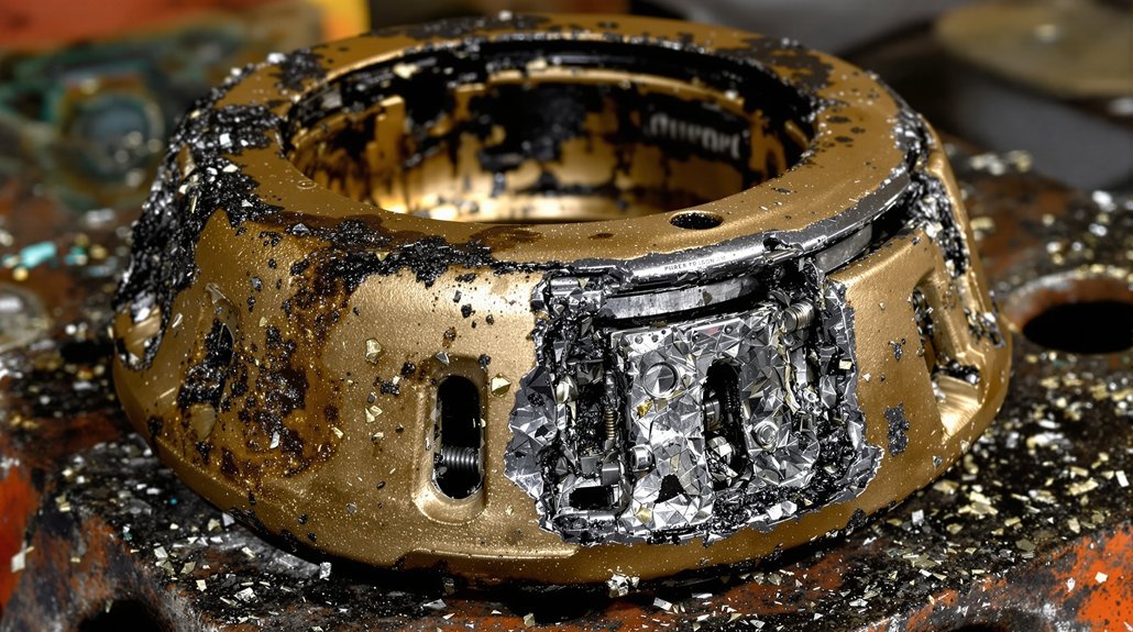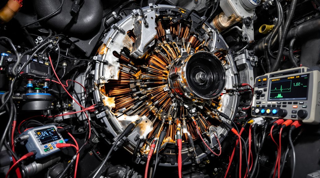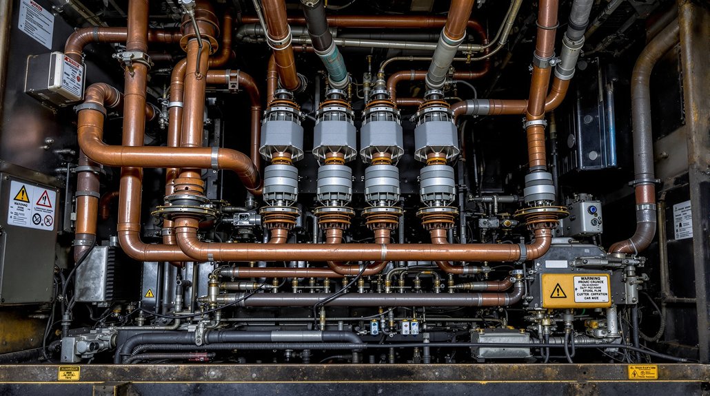
5 Semiconductor Diode Failure Symptoms in EMD Locomotives

5 Semiconductor Diode Failure Symptoms in EMD Locomotives

You’ll notice five key semiconductor diode failure symptoms in EMD locomotives: increased forward voltage drops, unusual heat generation, fluctuations in output voltage, elevated reverse leakage currents, and unexpected circuit interruptions. These signs often stem from overvoltage damage, thermal stress, overstress, or electrostatic discharge. Such degradation impacts excitation control and voltage regulation, risking system reliability. Understanding these symptoms helps you catch early faults and protect your traction systems—explore further to uncover the underlying causes and mitigation tactics.

Key Takeaways

  • Increased forward voltage drop and reverse leakage current indicate diode degradation in EMD locomotive systems.
  • Unusual heat generation and thermal imbalances signal potential diode overheating or thermal stress.
  • Fluctuations and ripple in output voltage reflect diode failure affecting excitation control and voltage regulation.
  • Sudden loss of rectification or voltage clamping failure suggests overvoltage-induced diode damage.
  • Inconsistent electrical performance and possible short or open circuits reveal mechanical or electrical diode faults.

Signs of Overvoltage-Induced Diode Damage

overvoltage diode damage indicators

When overvoltage pulses exceed design limits, semiconductor diodes in EMD locomotives often suffer immediate electrical failures, such as dielectric breakdown that causes shorts or open circuits. You’ll notice overvoltage symptoms like sudden loss of rectification or clamping in voltage regulation circuits, often triggered when Zener diodes experience reverse voltage beyond breakdown specifications. This can lead to voltage spikes bypassing protective elements, destroying diode junctions. Diode degradation manifests progressively; forward voltage drops increase beyond specified values, and reverse leakage currents rise, undermining clamping capabilities in TVS diodes during transient events.

You might detect erratic voltage regulation or reduced current handling without visible damage, complicating diagnostics. At the component level, degraded diodes often show reverse recovery times exceeding normal parameters and capacitance values deviating from datasheet specs. Recognizing these precise overvoltage symptoms and signs of diode degradation allows you to pinpoint failures early, ensuring timely maintenance and preventing system-level disruptions in locomotive power systems. Accurate voltage measurements with a true-RMS voltmeter are essential to correctly identify voltage irregularities that may lead to diode failure, since ordinary meters can give misleading readings with non-sinusoidal waveforms true-RMS measurement.

Indicators of Thermal Stress in Diode Components

thermal stress indicators in diodes

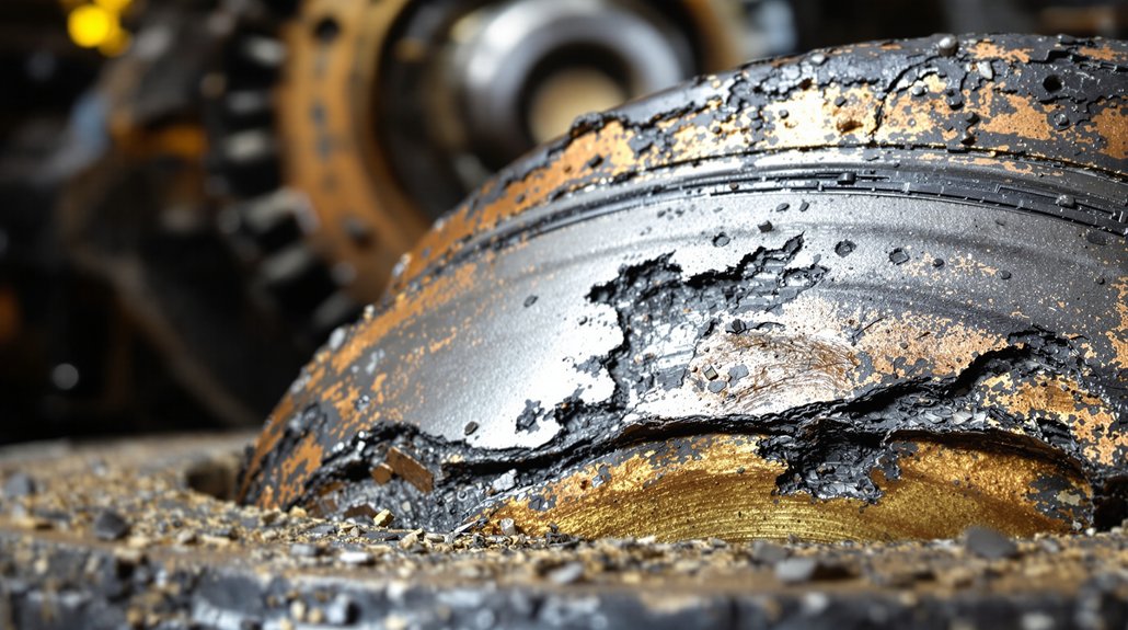
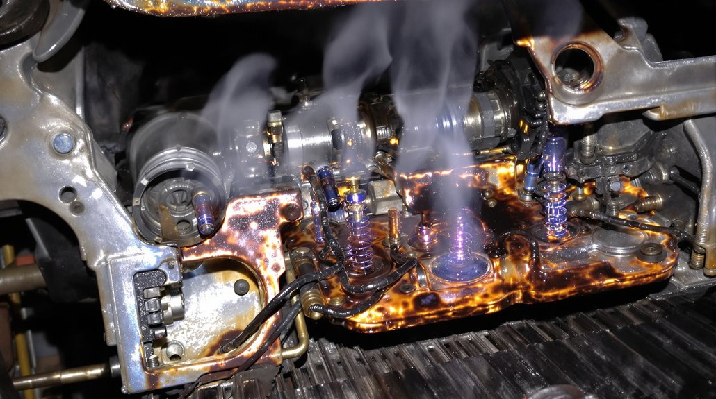
Although semiconductor diodes in EMD locomotives are designed to operate within specific thermal limits, you’ll observe clear indicators of thermal stress that degrade their performance over time. Thermal monitoring and diode diagnostics reveal characteristic signs such as shifts in forward voltage and increased reverse leakage currents, both reflecting internal material changes. Prolonged exposure leads to mechanical fatigue in bond wires and altered electrical parameters, challenging predictive maintenance.

Key thermal stress indicators include:

Key thermal stress indicators include shifts in voltage, increased leakage, discoloration, and altered electrical behavior.

  • Deviations from ideal exponential I-V curves, indicating “soft” breakdown.
  • Prolonged reverse recovery time under elevated temperatures.
  • Visible discoloration or dross formation on diode surfaces.
  • Increased electrical noise during load operation.
  • Gradual shifts in critical voltage thresholds and diode capacitance.
  • Additionally, electrical overstress from large pulsed voltages or currents can accelerate diode degradation.

Accurate thermal monitoring proves difficult due to sensor placement and environmental gradients, requiring sophisticated diode diagnostics to differentiate genuine thermal stress from transient anomalies. Recognizing these indicators helps you prevent sudden diode failures and optimize locomotive reliability.

Effects of Overstress and Electrostatic Discharge on Diodes

diode overstress and protection

Since semiconductor diodes in EMD locomotives endure complex electrical environments, they often face overstress and electrostatic discharge (ESD) conditions that compromise their integrity. Overstress from high current surges or voltage spikes can cause thermal runaway, junction avalanche, and material degradation, initiating diode failure. ESD events induce metal interconnect burnout, gate oxide rupture, and junction breakdown, damaging the diode’s critical structures. Because ESD is a transient discharge resulting from static charge accumulation, it can create large current flows that severely damage ICs if not properly managed, emphasizing the importance of understanding the ESD mechanisms involved.

Effective ESD protection employs low-clamp voltage diodes, optimized dynamic resistance, and on-chip protective structures to limit surge impact. Failure symptoms include leakage currents, short circuits, and resistance increases, often stemming from inadequate surge energy redirection or faulty clamps.

Overstress ConditionESD Failure ModeESD Protection Strategy
High current surgesMetal interconnect burnLow-clamp voltage diodes
Voltage spikesGate oxide ruptureDynamic resistance optimization
Prolonged rush currentsJunction breakdownOn-chip protective structures
Faulty clamp circuitsContact spike damageSurge current redirection

Maintaining robust ESD protection is essential to prevent diode failure in these demanding applications.

Characteristics of Degraded Semiconductor Diodes

degraded diode performance indicators

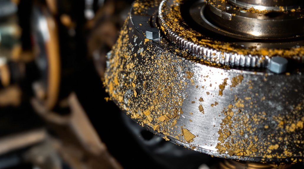
Degraded semiconductor diodes display distinct electrical and physical changes that signal declining performance and imminent failure. You’ll notice shifts in electrical parameters such as increased reverse leakage current and elevated forward voltage drops, accompanied by altered I–V characteristic curves. These symptoms arise from underlying degradation mechanisms like ion migration and defect accumulation under forward bias. Microstructural defects—including radiation-induced recombination centers and crystal lattice imperfections—further compromise diode integrity.

Key characteristics include:

  • Rapid current spikes beyond critical voltage thresholds
  • Mechanical lead separation reducing electrical continuity, which can cause an increase in thermal resistance and further deterioration
  • Microplasma emissions under reverse bias revealing gap breakdown
  • Progressive “walkout” phenomena preceding failure
  • Partial recovery of function after thermal annealing

Understanding these precise indicators helps you identify diodes under stress and anticipate failure, enabling timely maintenance to prevent operational disruption in EMD locomotives.

Operational Consequences of Diode Failures in EMD Traction Systems

diode failure operational challenges

When semiconductor diodes fail in EMD traction systems, you’ll encounter a cascade of operational challenges that directly impact excitation control and voltage regulation. Diode failure mechanisms, such as shorted or open diodes, increase excitation currents that overload exciter rotor windings, risking burnout. Voltage ripple influx damages regulators, especially those lacking over-excitation protection, while terminal voltage collapse from fully shorted diodes causes excitation loss. These excitation system impacts degrade no-load voltage stability and force regulators into maximum output modes, risking rotor damage.

Additionally, overcurrent stresses accelerate component wear, and transient events exacerbate diode degradation. Thermal imbalances from differential loading heighten failure rates, while excitation surges can propagate bus faults, threatening motor insulation. Protective systems may prematurely trip, causing shutdowns and operational delays. Maintenance complexity rises as full-diode replacements become necessary due to undetectable collateral damage, increasing diagnostic demands and inventory costs. Regular inspections and proactive maintenance are crucial to detect early signs of diode deterioration and prevent catastrophic failures. Overall, diode failures critically compromise system reliability, demanding vigilant monitoring and timely interventions to mitigate excitation and voltage regulation disruptions.

Frequently Asked Questions

How Can I Test Diode Health Without Removing It From the Circuit?

Think of diode testing methods as a detective maneuvering through a maze—you’re tracing paths without disturbing the walls. You’ll use multimeter diode test mode to spot forward voltage drops and look for reverse bias resistance. Power off the circuit, isolate one diode leg if needed, and watch for parasitic paths that can mislead you. Circuit analysis techniques like load testing or comparing against known values help confirm diode health without removal, ensuring precise, in-circuit diagnostics.

What Replacement Diode Types Are Compatible With Older EMD Locomotive Systems?

When selecting replacement diode brands for older EMD locomotive systems, you’ll want to prioritize compatibility factors like voltage class and insulator type. Universal diodes designed for EMD’s GP, SD, and F-series locomotives offer broad cross-model compatibility, simplifying repairs. Brands from authorized vendors like LocomotivePartsOnline.com provide accurate part numbers and quality options, including new and budget-friendly units. Always verify voltage ratings to avoid circuit damage and guarantee seamless integration with existing subsystems.

Are Thermal Imaging Scans Effective for Routine Diode Maintenance?

Think of thermal imaging as your eyes seeing the invisible heat signatures dancing on circuit surfaces. For routine maintenance, it’s highly effective—thermal imaging pinpoints temperature anomalies early, catching potential diode issues before they escalate. By integrating this non-intrusive method, you reduce downtime and enhance safety, ensuring precise diagnostics. However, remember it only detects thermal faults, so combine it with other tests for thorough diode health assessment during routine maintenance.

How Does Environmental Cycling Accelerate Diode Degradation?

You’ll find that environmental cycling accelerates diode degradation by imposing repeated thermal and mechanical stress, which shortens diode lifespan. The fluctuating temperatures cause mismatched expansion between materials, leading to microcracks and voids at interfaces. This environmental stress weakens metallization and die attach layers, increasing electrical resistance and reducing thermal conductivity. Over time, these effects compound, driving progressive failure mechanisms that degrade diode performance and reliability markedly faster than steady-state conditions.

What Are Best Practices to Prevent Electrostatic Discharge During Diode Handling?

You wouldn’t handle a delicate watch with greasy hands, so don’t touch diode leads directly—use handling techniques that focus on insulated regions. Preventive measures like grounding wrist straps, conductive work surfaces, and ionizers neutralize static charges effectively. Avoid insulative materials and store components in shielded packaging to minimize risk. Regularly monitor grounding systems and ionizer performance, ensuring your environment stays balanced and electrostatic discharge is prevented during diode handling.

5 Best EMD Locomotive Diode Rectifier Upgrades

5 Best EMD Locomotive Diode Rectifier Upgrades

You can greatly boost your EMD locomotive’s performance by upgrading diode rectifiers with advanced tech. Integrate silicon-controlled rectifiers (SCRs) for precise phase control and regenerative braking. Adopt high-current IGBTs to improve switching efficiency and thermal handling. Use modular thermal baseplates to optimize heat dissipation, ensuring reliability. Deploy 18kW PWM-controlled battery charging modules for stable voltage under varying engine speeds. Finally, switch to maintenance-free bearings paired with advanced electrical testing for extended service life. Let’s explore these upgrades in greater detail.

Key Takeaways

  • Upgrade to SCR-based rectifiers for phase-controlled AC-to-DC conversion with adjustable output and regenerative braking support.
  • Use high-current IGBT modules (3.3 kV/4.5 kV, up to 3600 A) for efficient, compact inverters with low switching losses.
  • Implement modular thermal baseplates to isolate heat zones, enhance cooling, and enable easy component replacement.
  • Deploy 18kW PWM-controlled battery charging rectifiers for stable 74V output and dynamic engine speed adaptation without recalibration.
  • Transition to maintenance-free bearings and apply advanced electrical testing for improved alternator longevity and voltage stability verification.

Integration of Silicon-Controlled Rectifiers (SCRs) in Bridge Circuits

scrs enhance bridge circuits

Although traditional diode bridge rectifiers have served reliably in EMD locomotive power systems, integrating Silicon-Controlled Rectifiers (SCRs) greatly enhances control and efficiency by enabling phase-controlled AC-to-DC conversion. You gain significant SCR advantages, such as adjustable output voltages achieved by triggering conduction during specific AC cycle segments. This allows for precise power regulation tailored to dynamic load demands, optimizing traction motor performance. SCR-based bridges also support bidirectional current flow in latent conduction modes, critical for regenerative braking operations, thereby improving system flexibility.

Retrofitting existing diode infrastructures with gate control circuitry lets you leverage these benefits without complete hardware replacement. Additionally, SCRs exhibit lower switching losses in high-current contexts, enhancing thermal efficiency and reliability. By actively controlling conduction angles, you minimize energy waste and improve overall power quality. This integration transforms passive rectification into an adaptable, efficient solution for variable locomotive operational states, marking a substantial advancement over conventional diode bridge configurations. Moreover, SCRs can be triggered by applying a small voltage to the gate terminal, allowing intentional gate triggering for precise conduction control.

Adoption of Insulated-Gate Bipolar Transistors (IGBTs) for High-Voltage Management

high voltage igbt advantages

When managing high-voltage demands in EMD locomotive power systems, adopting Insulated-Gate Bipolar Transistors (IGBTs) offers significant advantages over traditional components. You benefit from precise voltage management via IGBT modules rated at 3.3 kV and 4.5 kV with current capacities up to 3600 A. These IGBT advantages include lower switching losses, higher frequency operation, and robust thermal performance between -40°C and +150°C, ensuring reliability even under locomotive vibrations and rapid power cycling. The standard-type package design with a rectangular footprint of 190 mm x 140 mm provides high current capacity and flexibility for various converter topologies.

ParameterTraditional GTOs/SCRsIGBT Modules
Voltage RatingUp to 3 kV3.3 kV – 4.5 kV
Current Handling≤ 2000 AUp to 3600 A
Switching FrequencyLow (few kHz)High (tens of kHz)
Thermal RangeNarrow-40°C to +150°C
EfficiencyLowerHigher, reducing heat load

This technology enables compact, efficient, and scalable inverter designs critical for modern EMD locomotives.

Implementation of Modular Thermal Baseplates for Enhanced Heat Dissipation

modular thermal baseplates enhance cooling

Since efficient heat dissipation is critical for maintaining diode and rectifier reliability, modular thermal baseplates have been implemented to isolate thermal zones and optimize cooling. By minimizing thermal coupling between components, these baseplates maintain stable junction temperatures, preventing performance degradation. You’ll benefit from precise positioning of diodes and rectifiers on isolated thermal zones, which reduces cross-heating effects. This method complements essential thermal management practices necessary in high-voltage power systems to ensure safety and performance.

Key advantages include:

Key advantages include enhanced heat transfer, modular maintenance, reduced thermal stress, and scalable power support.

  1. Use of high-conductivity materials in baseplates guarantees rapid heat transfer, enhancing thermal management under peak loads.
  2. Engineered pathways facilitate efficient airflow and integration of heat sinks adjacent to thermal bases.
  3. Modular design allows you to replace individual components without disturbing the entire assembly, simplifying maintenance.
  4. Thermal stress is mitigated by distributing heat away from sensitive junctions, maintaining operational integrity under high-current scenarios.

This approach preserves electrical continuity and supports scalable power demands, guaranteeing robust, reliable locomotive diode rectifier performance.

Deployment of 18kW PWM-Controlled Battery Charging Rectifier Modules

pwm rectifier modules upgrade

As you upgrade your locomotive’s battery charging system, deploying the 18kW PWM-controlled rectifier modules offers precise voltage regulation and enhanced efficiency. These modules deliver a continuous 18 kW output with a tightly controlled 74V ±1V voltage range, adapting dynamically across engine speeds from 200 to 900 RPM via 500Hz PWM control. This guarantees stable charging despite throttle fluctuations. The EMD 645 series engines, known for their robust two-stroke design and compatibility with legacy parts, provide a reliable platform for such modern upgrades.

Retrofit benefits include direct board-level compatibility with legacy EMD 845/847 systems, eliminating calibration needs and reducing maintenance downtime. The design’s robust thermal tolerance (-40°C to +50°C operating) and dual-layer over-voltage protection assure reliable operation under harsh rail conditions. By integrating software-monitored diagnostics, you gain real-time voltage and current anomaly detection, optimizing operational efficiency. Additionally, their modular architecture allows single-unit replacement during overhauls, minimizing service interruptions. Overall, these rectifier modules enhance power source flexibility by supporting D14 alternators and 3-phase inputs, future-proofing your fleet with scalable, maintenance-friendly upgrades.

Transition to Maintenance-Free Bearings and Advanced Electrical Testing Protocols

maintenance free bearings upgrade

Building on the enhanced efficiency and reliability achieved through the deployment of 18kW PWM-controlled rectifier modules, addressing mechanical and diagnostic advancements further elevates system performance. You’ll find that shifting to maintenance-free bearings greatly boosts bearing durability and reduces downtime. These sealed-clean designs prevent contamination, extending alternator rebuild intervals to 12 years. This approach aligns with best practices in maintenance schedules, optimizing intervals based on engine usage and conditions. Simultaneously, advanced electrical testing protocols guarantee peak voltage stability and early fault detection.

Key upgrades include:

  1. Integration of OEM-specified, high-performance bearings that eliminate grease maintenance and reduce failure under peak loads.
  2. Surge comparison and rectifier bank diagnostics to validate voltage stability and power conversion efficiency post-rebuild.
  3. Stator core loss analysis combined with automated data logging for predictive maintenance insights.
  4. Standardized pre/post-rebuild benchmarking to confirm compliance with voltage regulation tolerances.

Frequently Asked Questions

How Do Upgraded Rectifiers Impact Locomotive Fuel Efficiency?

Upgraded rectifiers improve fuel consumption like a conductor fine-tuning an orchestra, ensuring each component performs most effectively. You’ll see energy savings because these rectifiers convert AC to DC more efficiently, reducing power loss. This precision minimizes wasted energy, so your locomotive uses less fuel to generate the same output. By enhancing current regulation and reducing thermal losses, you maximize engine efficiency, directly lowering operational costs and boosting overall fuel economy.

What Are the Cost Differences Between Old and New Rectifier Systems?

When you analyze the cost comparison between old and new rectifier systems, you’ll find new systems typically have higher upfront costs but offer superior system efficiency. This efficiency leads to lower maintenance and energy expenses over time. Older systems require frequent diode and fuse replacements every 10 years, increasing lifecycle costs. In contrast, modern designs reduce component failures and downtime, providing better long-term value despite initial capital outlay.

Can These Rectifier Upgrades Be Retrofitted to Older Locomotive Models?

You’d think retrofitting older locomotives with new rectifiers is as complex as rewiring a skyscraper, but retrofit feasibility is surprisingly high. Thanks to standardized electrical layouts, these upgrades offer excellent model compatibility, fitting seamlessly into legacy systems. Modular designs and direct drop-in replacements minimize installation challenges, and non-calibration setups reduce downtime. So, you can confidently update older models without extensive modifications, ensuring technical precision and operational reliability.

What Is the Expected Lifespan of Upgraded Diode Rectifier Components?

You can expect diode longevity of upgraded rectifier components to extend well beyond standard 10-year replacement intervals, often reaching 12 years or more with proper maintenance. This enhanced component reliability stems from advanced insulation materials, improved cooling, and regenerative braking systems that reduce thermal stress. By adhering to rigorous testing and overhaul schedules, you guarantee sustained performance and minimized electrical wear, maximizing the service life of these diode assemblies under typical operating conditions.

How Do Rectifier Upgrades Affect Overall Locomotive Noise Levels?

You’ll notice that rectifier upgrades greatly improve noise reduction by stabilizing DC output, which leads to better vibration control in traction motors. These enhancements minimize harmonic interference and current spikes, reducing audible hum and mechanical vibrations. By integrating advanced insulation and noise suppression circuits, you’ll experience less electromagnetic interference. Overall, these upgrades deliver smoother voltage regulation, cutting down both electrical and mechanical noise, resulting in quieter, more efficient locomotive operation.

Why Replace Pneumatic Control System Diaphragms Regularly?

Why Replace Pneumatic Control System Diaphragms Regularly?

You’ll prevent 12% of valve failures by replacing diaphragms before cyclic stress and chemical exposure cause ruptures. Your diaphragms face millions of pressure cycles, thermal-induced corrosion, and humidity that doubles degradation rates above 60%. Worn diaphragms compromise brake effectiveness, increase fuel consumption from compressor overwork, and violate 49 CFR 236.590 compliance requirements. Preventive replacement costs 40% less than emergency repairs while maintaining consistent pressure transmission and extending actuator lifespan throughout your pneumatic system.

Key Takeaways

  • Cyclic mechanical stress and chemical exposure progressively degrade diaphragm materials, leading to fatigue, cracking, and eventual catastrophic failure.
  • Worn diaphragms compromise system performance, causing pressure inconsistencies, extended response times, and reduced operational efficiency across pneumatic controls.
  • Regular replacement prevents unexpected breakdowns that result in costly emergency repairs, production downtime, and accelerated wear of connected components.
  • Federal regulations mandate specific inspection intervals and maintenance documentation for pneumatic control systems to ensure safety and compliance.
  • Proactive diaphragm replacement based on manufacturer specifications extends system lifespan and reduces total ownership costs by 40%.

Understanding Diaphragm Material Degradation in Locomotive Pneumatic Systems

diaphragm material fatigue monitoring

When cyclic mechanical stress repeatedly flexes a diaphragm during pneumatic operations, the material undergoes progressive fatigue that ultimately leads to failure. You’ll observe this diaphragm fatigue accelerate as high air pressure increases flexion rates, shortening operational lifespan. Your system’s valve balls and seats create abrasion patterns on diaphragm surfaces, especially when handling particulate-laden fluids. Regular system maintenance schedules prevent excessive wear by ensuring worn components are replaced before catastrophic failure occurs.

Material properties degrade through multiple pathways. High ambient temperatures reduce elastomer flexibility while increasing brittleness. You’re facing thermal cycling that compounds polymer degradation, while low-temperature exposure increases rigidity and limits compliance during pneumatic cycles. Vibration from unbalanced systems induces microscopic tears that propagate through the material structure.

Fluid viscosity changes alter diaphragm movement efficiency, creating irregular wear patterns. When overpressure events occur, sudden stress spikes push materials beyond yield points. You must monitor heat transfer from adjacent components, as localized deterioration considerably impacts diaphragm integrity and performance metrics.

Chemical Exposure and Corrosion Effects on WABCO Control Diaphragms

chemical degradation prevention measures

Three primary chemical mechanisms systematically degrade Wabco control diaphragms in locomotive pneumatic systems. First, thermal-induced reactions cause oil particles to release esters and aerosols, creating corrosive compounds that attack diaphragm surfaces. You’ll observe accelerated deterioration when oil-crack products accumulate, especially in high-temperature zones above 140°F.

Second, dissolved gases like CO2 and H2S combine with moisture to form acidic solutions. These acids penetrate diaphragm materials, causing embrittlement and microscopic cracking. When humidity exceeds 60%, chemical interaction rates double, reducing diaphragm lifespan by 40%. Additionally, microbially induced corrosion develops when bacteria colonies form in moisture-rich environments, producing metabolic byproducts that further compromise diaphragm integrity.

Third, electrolyte infiltration in 0.025–0.1mm gaps triggers localized crevice corrosion. You’ll find concentrated damage at mounting points where moisture accumulates.

For effective corrosion prevention, install desiccant cartridges with coalescence filters to remove aerosolized contaminants. Replace standard diaphragms with 316L stainless steel-reinforced variants. Schedule monthly connector cleaning to eliminate moisture buildup. These measures extend diaphragm service life from 18 to 36 months.

Preventing Catastrophic Failures Through Scheduled Diaphragm Maintenance

scheduled diaphragm maintenance optimization

You’ll need systematic risk assessment methods to identify critical failure points before diaphragm ruptures compromise your HAZMAT systems or trigger unplanned shutdowns. By analyzing cyclic stress patterns, chemical exposure data, and historical failure rates, you can predict when micro-cracks will propagate into catastrophic breaks. Your maintenance schedule optimization should align replacement intervals with measured degradation curves, ensuring you’re replacing diaphragms at 80% of their statistical failure point rather than waiting for emergency repairs that cost three times more than planned replacements. Running AODD pumps dry accelerates wear through excessive speed increases and compressed air consumption, making dry-run monitoring essential for maintaining your predictive maintenance accuracy.

Risk Assessment Methods

While pneumatic control systems operate reliably for thousands of cycles, diaphragm failures can trigger catastrophic events that shut down entire production lines or compromise safety-critical functions. You’ll need systematic diaphragm evaluation methods to predict failures before they occur.

FMEA analysis helps you identify failure modes and calculate Risk Priority Numbers (RPN) for each component. By tracking stroke counts and pressure logs, you can establish failure prediction models specific to your operating conditions. Studies show that diaphragm damage accounts for 12% of pneumatic control valve failures in industrial applications, making it a critical monitoring priority.

Risk FactorIndustry Impact
Diaphragm Rupture72-hour production shutdown
AOV FailureNuclear safety system compromise
Actuator Malfunction$2.4M chemical spill liability
Undetected Leakage15% efficiency loss daily

Root cause analysis of historical failures reveals patterns that inform your replacement schedules. Combine visual inspections with data analytics to optimize maintenance intervals.

Maintenance Schedule Optimization

Once diaphragm failures exceed acceptable risk thresholds, your maintenance schedule becomes the primary defense against unplanned shutdowns. You’ll need to establish cyclical protocols: weekly visual inspections, monthly air valve cleaning, and annual diaphragm overhauls. Use stroke counters and maintenance technology to track pump cycles against manufacturer specifications. Monitor diaphragm performance through key metrics—stroke rate, air pressure consistency, and fluid discharge patterns.

Document historical maintenance data to identify failure patterns specific to your applications. Align inspection frequency with operating conditions: aggressive chemicals demand weekly checks, while standard applications require quarterly assessments. Install upstream air filters to preserve diaphragm integrity and implement torque verification protocols. Avoid tightening hardware components while the system remains under pressure to prevent seal damage and premature diaphragm failure. Store categorized spare diaphragms based on material compatibility and shelf life to guarantee rapid replacement capability.

Impact of Worn Diaphragms on Braking System Performance and Safety

worn diaphragms compromise braking safety

Worn diaphragms create cascading failures throughout your braking system that directly threaten vehicle safety and operational efficiency. As diaphragm performance degrades, you’ll experience compromised force transmission through misaligned mechanical linkages, reducing brake shoe contact effectiveness by up to 40%. Your system’s pressure regulation becomes unreliable, with cracked diaphragms causing inconsistent build-up rates that extend stopping distances beyond acceptable safety margins. These mechanical failures particularly impact modern PEBS systems where precise pressure control is essential for Advanced Driver-Assistance Systems functionality.

The safety implications extend beyond basic braking deficiency. You’re facing increased collision risks from unpredictable pressure drops that disable emergency brake engagement when you need it most. Position feedback errors in automated systems cause missed stops, while unstable air regulation prevents achieving target braking pressures. These failures accelerate component wear across S-cams, push rods, and brake shoes, creating unbalanced forces that damage road-facing components. Your operational costs escalate through increased fuel consumption from frequent compressor activation and premature component replacement cycles.

Regulatory Requirements for Pneumatic Control System Maintenance in Rail Transport

pneumatic system maintenance regulations

You must comply with federal regulations 49 CFR 236.590 and 238.309, which mandate specific inspection intervals and documentation requirements for pneumatic control systems. The 49 CFR 236.590 specifically addresses safety and operational standards for pneumatic apparatus in railroad operations. Your replacement diaphragms need material certification that meets OEM specifications and regulatory standards for safety-critical components. You’re required to maintain detailed inspection logs, perform maintenance at 736-day intervals for systems without air dryers, and guarantee all maintenance personnel complete certification programs covering both technical procedures and compliance protocols.

Safety Standards Compliance

When maintaining pneumatic control systems in rail transport, you’re required to comply with extensive federal regulations outlined in 49 CFR Part 236, which governs the installation, inspection, maintenance, and repair of signal and train control systems. You must follow specific standards under § 236.590, mandating inspection, cleaning, and documentation of pneumatic apparatus including train stops and control systems.

Your compliance strategies should incorporate multi-layered regulatory requirements spanning federal, state, and local jurisdictions. You’ll need to maintain detailed inspection records aligning with safety audits and reporting requirements. For passenger coaches equipped with AB-type brake systems, maintenance intervals extend to 2,208 days, demonstrating how specific equipment configurations determine regulatory compliance schedules. While you can petition the FRA for alternative procedures offering equivalent safety measures, you must strictly follow federal guidelines unless approved otherwise. Rail transit systems may impose additional maintenance frequencies beyond federal mandates, requiring you to adapt your compliance framework accordingly.

Material Certification Requirements

Material certification requirements form the foundation of regulatory compliance when replacing pneumatic control system diaphragms in rail transport. You must maintain complete material traceability documentation linking every replacement component to its original certification. Your replacement diaphragms need ASTM/AAR/EN compliance certificates that verify pressure-bearing capabilities and operational durability under specified conditions.

During certification audits, you’ll present these documents to prove adherence to 49 CFR Part 236 and OEM specifications. You’re required to use certified alternatives when original materials become obsolete, ensuring they meet manufacturer-approved interchangeability standards. Your maintenance logs must include certification details for each diaphragm replacement, creating an auditable trail. Post-replacement pressure testing validates that certified materials maintain system integrity, meeting both federal regulations and RTD-recommended maintenance frequencies.

Inspection Schedule Mandates

While material certifications establish the foundation for compliance, inspection schedule mandates create the operational framework that keeps your pneumatic control systems functioning reliably throughout their service life.

Federal regulations dictate your inspection frequency requirements:

  1. 49 CFR §236.590 – You must inspect and clean pneumatic apparatus regularly
  2. 49 CFR §299.445 – You’ll follow OEM-recommended intervals for safety-critical components
  3. Monthly inspections – You’re required to check slip rails, expanders, and lubrication systems
  4. Post-maintenance testing – You must validate functionality before returning equipment to service

Your written inspection program must detail procedures for pre-service inspections every two calendar days to ensure safety-critical pneumatic components remain operational. Your maintenance documentation must capture equipment IDs, defect dates, and test results per §229.29(a). You’ll track pneumatic leaks, valve wear, and pressure anomalies systematically. RCM programs help you optimize inspection cycles based on historical failure data and environmental factors affecting your system’s reliability.

Cost Analysis of Preventive Diaphragm Replacement Versus Emergency Repairs

preventive replacement reduces costs

Two key financial metrics drive the decision between preventive diaphragm replacement and emergency repairs: total cost of ownership and operational downtime expenses. You’ll find preventive replacement yields lower upfront costs compared to reactive purchases, while emergency repairs demand higher immediate spending for urgent parts and labor.

Your cost benefit analysis reveals preventive strategies enable predictable budgeting through scheduled maintenance cycles. You’re avoiding hidden expenses like lost productivity during unscheduled downtime. Emergency response fees and limited specialized diaphragm availability during crises compound reactive maintenance costs. Plant downtime due to pump failure incurs significant financial losses that far exceed the cost of scheduled replacements.

Through lifecycle management, you’ll achieve substantial savings from reduced replacement frequency and prolonged system lifespan. Preventive schedules guarantee minimal operational stoppages, maintaining production continuity. You’re preserving ideal airflow and reducing gas consumption with properly functioning pneumatic systems.

The data confirms preventive diaphragm replacement minimizes total ownership costs while maximizing operational efficiency. You’ll benefit from simplified part replacement, predictable labor costs, and extended warranty periods for newly replaced components.

Signs of Diaphragm Wear and Establishing Replacement Intervals

diaphragm replacement monitoring guidelines
  1. Cycle count monitoring – Replace diaphragms after exceeding manufacturer-specified thresholds
  2. Pressure testing results – Schedule replacement when baseline pressure exceeds design limits
  3. Visual damage assessment – Replace units showing tears, deformation, or corrosion
  4. Performance degradation – Monitor flow rate inconsistencies and positioning control accuracy

You’ll establish effective replacement intervals by tracking these indicators systematically. Document pressure fluctuations, actuator response times, and vacuum test results. When multiple symptoms appear simultaneously, immediate replacement prevents catastrophic failure. Regular monitoring transforms reactive maintenance into predictive scheduling, optimizing system reliability while minimizing downtime costs.

Maintaining Operational Efficiency Through Proactive Diaphragm Management

proactive diaphragm management efficiency

After implementing systematic monitoring protocols, you’ll maximize operational efficiency through strategic diaphragm management that transforms maintenance from reactive firefighting to predictive optimization. You’re eliminating variable flow rates caused by worn diaphragms while guaranteeing precise control through clean actuators and aligned mechanisms.

Track performance metrics including pressure consistency, throttle response times, and seal integrity data. You’ll prevent diaphragm-induced vibrations that disrupt system stability by replacing components before degradation impacts diaphragm functionality. Document flow variations, actuation speeds, and leakage rates to establish replacement baselines.

Your proactive approach reduces emergency repair costs while minimizing production downtime. You’re extending actuator lifespan by eliminating strain from malfunctioning diaphragms and preventing stem misalignment through scheduled replacements. Energy consumption drops considerably when efficient fluid transfer isn’t compromised by leakage. This strategic management guarantees bubble-tight sealing during shutdowns, maintains consistent process control, and demonstrates regulatory compliance through documented maintenance records.

You may also like to read – How to Replace WABCO Locomotive Brake Diaphragms

Frequently Asked Questions

Can Diaphragms Be Repaired Instead of Replaced Entirely?

Like patching a leaking dam, you can repair diaphragms with surface-level fixes using chemical solvents or lubrication for minor damage. However, diaphragm repair feasibility depends on damage severity. Full-thickness tears, chemical degradation, or delamination require replacement. While surface repairs offer cost-effective short-term solutions, repair feasibility diminishes with extensive damage. You’ll find that standardized replacement often proves more reliable than attempting repairs on critically compromised components.

What Tools Are Needed for Diaphragm Replacement Procedures?

You’ll need specific diaphragm replacement tools for proper installation. Use socket wrenches to disassemble valve housings, torque-limiting screwdrivers to prevent seal damage, and needle-nose pliers for positioning new diaphragms in tight spaces. Following maintenance best practices, you’ll require scalable cleaning brushes to prepare sealing surfaces and remove debris. Don’t forget manufacturer-specified torque wrenches for reassembly and specialized diaphragm pullers if the component’s bonded to metal plates.

How Do Temperature Fluctuations Affect Diaphragm Replacement Frequency?

You’ll find temperature fluctuations greatly reduce your diaphragm lifespan through material degradation cycles. When temperatures exceed 60°C, synthetic rubbers deteriorate rapidly, while sub-4°C conditions cause hardening and brittleness. Your replacement frequency doubles with 20°C temperature swings occurring daily. Monitor thermal cycling data – each 10°C variation accelerates aging by 15%. Temperature impact manifests through expansion-contraction stress, creating microcracks that compromise structural integrity within 6-12 months versus 24-month stable-temperature operations.

Which Diaphragm Materials Offer the Longest Service Life?

Like a marathon runner’s shoes, your diaphragm materials determine operational endurance. You’ll maximize diaphragm durability by selecting Hytrel or Santoprene for their exceptional flex life—Hytrel achieves 10+ million cycles in clean applications. Material comparison reveals PTFE offers unmatched chemical resistance but costs 3-5x more. For balanced performance, you’re looking at thermoplastic elastomers providing 2-3 year service intervals versus 6-12 months for standard EPDM in demanding pneumatic systems.

Should Spare Diaphragms Be Stored in Specific Conditions?

You’ll need to maintain specific diaphragm storage conditions to preserve material integrity. Store spare diaphragms in dry, clean indoor environments at temperatures between 15-25°C, avoiding extremes above 60°C or freezing conditions. Keep them in original packaging to prevent contamination and UV exposure. Monitor the 5-year shelf life carefully, recording storage dates for traceability. These ideal conditions prevent premature degradation, ensuring diaphragms perform reliably when installed in your pneumatic systems.

7 Best WABCO Diaphragm Maintenance Procedures

7 Best WABCO Diaphragm Maintenance Procedures

You’ll maximize your WABCO diaphragm’s performance by replacing desiccant cartridges every 2-3 years, inspecting lip grooves for cuts and wear, and matching diaphragm styles to your valve housing type. Apply grease only to O-rings using WABCO-supplied lubricants, torque mounting bolts to 53 lb-in, position spring valve assemblies with cap lips facing outward, and conduct pressure tests at 6 bar. Master these procedures to prevent costly breakdowns and extend component life considerably.

Key Takeaways

  • Inspect diaphragm lip grooves for cuts, wear, radial scoring, and sludge buildup during routine maintenance checks
  • Apply grease only to O-rings using WABCO-supplied kits, never on diaphragm surfaces
  • Replace diaphragms showing tears, persistent leaks, brittleness, or permanent deformation immediately
  • Torque valve housing mounting bolts to 53 lb-in and document all values
  • Test seal integrity at 6 bar pressure using bubble detection fluid

Replace Desiccant Cartridges Every 2-3 Years Based on Usage Patterns

monitor and replace cartridges

Your desiccant cartridge’s lifespan depends on three critical factors: operational intensity, environmental conditions, and maintenance quality. Standard cartridges last 2-3 years under normal conditions, but heavy-duty cycles cut cartridge longevity to 1-2 years. You’ll need faster replacements when running high compressor intensity or operating in humid climates where moisture accumulation accelerates.

Monitor your usage impact closely. Intermittent operation extends lifespan, while continuous runs demand vigilant replacement schedules. Check for water accumulation in tanks – it’s your primary saturation indicator. When you spot moisture in airflow or contaminated output, replace immediately regardless of timeline. Additionally, maintain a consistent drainage schedule every 2 months or 2,000 miles to prevent moisture buildup that degrades cartridge performance.

Coalescing cartridges require 1-2 year intervals due to higher filtration demands. After compressor overhauls, mandatory replacement guarantees system integrity. Maintain proper drainage and bypass valve functionality to maximize cartridge performance. Track operational gaps and adjust replacement frequency based on actual duty cycles rather than calendar dates alone.

Inspect Diaphragm Lip Grooves for Damage and Wear Indicators

inspect diaphragm groove damage

You’ll need to visually examine the diaphragm lip grooves after disassembly, looking for deep cuts, worn surfaces, or radial scoring that could prevent proper sealing. Check for common damage patterns like sludge buildup, aging cracks, or groove ovality that indicate the diaphragm can’t maintain an airtight seal under compression. Replace the diaphragm immediately if groove damage compromises sealing capacity, as even minor defects can cause persistent air leaks and extended regeneration cycles.

Visual Inspection Methods

Three critical areas require careful examination when inspecting diaphragm lip grooves for damage and wear indicators. First, verify seal installation by confirming the lubricated lip faces away from the system. Check that it’s fully seated in the groove and remains concentric during operation. During this inspection, examine for cuts or bulges that would indicate the need for immediate replacement.

Second, perform groove assessment by scanning for radial cracks, fraying edges, and embedded debris. Look for uneven color changes indicating heat exposure or chemical damage. Third, evaluate lubrication condition across the entire lip surface. You’ll need to identify contaminants, check viscosity for hardening, and spot any lubricant breakdown. During inspection, note erosion patterns from abrasive particles and measure groove depth against maintenance specifications. These visual checks help you determine if replacement’s necessary before pressure retention failures occur.

Common Damage Patterns

When mechanical abrasion affects diaphragm lip grooves, you’ll spot distinct damage patterns that signal immediate maintenance needs. You’ll find cuts, embedded particles, and uneven contact surfaces that create leak paths. These indicators point to diaphragm failure if left unchecked.

Damage TypeMaintenance Tips
Grooves with cuts/particlesClean system, replace seals
Uneven wear surfacesCheck alignment, reseat properly
Stretched/ripped groovesRegulate pressure changes
Rubber delaminationReplace diaphragm immediately

Chemical contamination presents different challenges. You’ll encounter sludge blocking exhaust paths and grease migration causing valve seizures. Moisture creates corrosion at rubber-metal interfaces, weakening component adhesion. Regular inspection catches these patterns early, preventing costly repairs and system downtime.

Replacement Decision Criteria

After documenting damage patterns, your next critical step involves establishing clear replacement criteria for diaphragm lip grooves. You’ll need to monitor physical damage like tears, cuts, or irreversible deformation that compromise diaphragm longevity. When persistent leaks occur despite cleaning efforts, or sludge buildup exceeds your maintenance frequency capacity, it’s time for replacement.

Check for material degradation signs including brittleness, cracking, or hardened rubber that won’t seal properly. If you discover permanent groove misalignment that adjustments can’t fix, don’t hesitate to replace the component. Track your cleaning intervals and test results to predict replacement timing accurately. Remember, attempting repairs on severely damaged diaphragms wastes time and risks system failure. Replace immediately when you identify these triggers to maintain peak performance.

Match Diaphragm Styles to Specific Regeneration Valve Housing Types

diaphragm compatibility with valves

You’ll need to identify your specific regeneration valve housing type before selecting the correct diaphragm style. Check the housing’s bore diameter, mounting configuration, and pressure rating against manufacturer compatibility charts to guarantee you’re choosing a diaphragm that matches your valve’s exact specifications. The OE specification diaphragm ensures proper fit and function within WABCO regeneration valve systems. Cross-reference the housing part number with WABCO’s diaphragm catalog to confirm material compatibility, dimensional requirements, and operating pressure ranges.

Housing Type Identification

Several distinct regeneration valve housing types exist across WABCO’s air dryer product line, each requiring specific diaphragm configurations for proper operation. You’ll encounter variations in port arrangements, valve positioning, and heater placement that directly impact diaphragm alignment. Housing compatibility depends on matching your diaphragm to the exact valve body configuration.

Look for these key identifiers:

  1. Port Configuration – Check washer placements and bypass valve integration between inlet/outlet ports
  2. Material Numbers – Match valve body numbers (like 4324159222) to corresponding diaphragm specifications
  3. Visual Markers – Identify dots or arrows indicating proper diaphragm orientation

System Saver Plus models require purge-valve-centric diaphragms, while standard 1200/1800 series use different sealing approaches. Always cross-reference your housing type against technical bulletins before selecting replacement diaphragms.

Diaphragm Style Selection

Once you’ve identified your housing type, selecting the correct diaphragm style becomes critical for proper valve operation. You’ll need to match diaphragm materials to your specific valve requirements. For ABS housings, you’ll require specialized diaphragms like part #4725001000X, while UNISTOP™ diaphragms work specifically with WABCO service brake chambers.

Housing TypeDiaphragm SelectionKey Specifications
ABS/Load SensingSpecialized reinforcedHigh-temp resistant
Service BrakeUNISTOP™65-70 PSI pressure ratings
Proportional ValveGradual modulation typePressure gradient capable

Consider pressure ratings carefully—your diaphragm must handle peak system pressures while maintaining closing/opening specifications. Nitrile diaphragms offer excellent corrosion resistance for high-stress environments. Always verify material compatibility with your valve’s zinc diecast body and ascertain dimensional fit matches your housing’s port configuration.

Compatibility Cross-Reference Charts

Cross-referencing diaphragm styles to regeneration valve housings requires matching precise dimensional specifications with OEM part numbers. You’ll need to verify stroke lengths, cylinder dimensions, and port configurations before selecting replacement diaphragm types to avoid compatibility issues.

Here’s what you must check:

  1. Stroke measurements – Match your housing’s requirements (57.0mm, 63.5mm, or 76.2mm) with corresponding ProVia disc models like PRO 714 019 0 or PRO 714 020 0
  2. Port orientation – Confirm top/side port positions (0°, 20°, or 90°) align with your valve housing layout and thread specifications (M16×1.5)
  3. OEM cross-references – Use WABCO’s 815 010 054 3 document to verify DAF 1505241, Meritor SSP1438AF, or Abex ADB1438 equivalents match your system

Always confirm push rod lengths and mounting bolt spacing before installation.

Apply Grease Only to O-Rings Using Manufacturer-Supplied Lubricants

precise o ring lubrication required

When you’re servicing WABCO diaphragms, you’ll need to apply lubricants with surgical precision—grease goes only on O-rings and nowhere else. This critical distinction prevents contamination of diaphragm surfaces and maintains system integrity.

Use WABCO-supplied grease kits included in replacement packages for proper lubricant selection. DOT 3/DOT 4 brake fluid works for O-ring lubrication in hydraulic systems, while AAR Specification M-914 serves thread applications. Never substitute general-purpose grease—it’ll degrade seals and compromise performance.

During grease application, keep your tools clean and contaminant-free. Apply lubricant only to the O-ring itself, ensuring even coverage without over-lubrication. After installation, wipe down diaphragm surfaces to verify zero residual grease. Complete a post-replacement purge to clear any air or grease residue from the system. If you’ve accidentally contaminated restricted areas like control lines or regeneration valve mechanisms, disassemble immediately for cleaning. Remember: improper lubrication voids warranties and necessitates component replacement. MxV Rail’s testing facilities validate these maintenance procedures under real-world operating conditions to ensure maximum component reliability.

Torque Valve Housing Mounting Bolts to 53 Lb-In Specifications

torque specifications for valves

Grab your calibrated torque wrench and set it precisely—valve housing bolts demand exact specifications that vary by component type. You’ll find that WABCO’s torque specifications range widely depending on the valve assembly you’re servicing.

Here’s what you need to follow:

  1. Apply 18 lb-ft for Grade 8 cross-member mounting bolts—use prevailing torque nuts to combat vibration
  2. Torque cap screws to 22-25 lb-ft on tandem brake valves after applying Loctite 242
  3. Set 50-60 lb-ft for priority charging valve housing plugs in high-performance applications

Your mounting techniques directly impact valve performance. Sequence your torque steps when tightening multiple fasteners to prevent housing warpage. Don’t exceed manufacturer limits—over-tightening damages threads and compromises seal integrity. After torquing, verify housing alignment using templates and test for leaks with soap solution. Remember, modulating valves require 18-22 lb-ft while exhaust port plugs need only 20-24 lb-ft. Document all torque values for maintenance tracking.

Position Spring Valve Assembly With Cap Lip Facing Outward

During spring valve assembly installation, you’ll position the cap lip facing outward to ascertain proper diaphragm interaction and prevent internal component interference. Match the assembly’s directional indicators with housing markings while making sure spring alignment with the air port configuration.

Use installation tools to maintain parallelism as you guide the assembly into place. You’ll need to orient the cap lip toward the actuator access panels, following WABCO-specific diaphragm interaction guidelines. Check that the keyhole aligns correctly with the spring release mechanism before proceeding.

Apply controlled force to avoid deforming the lip during positioning. Once seated, verify your work through visual inspection and tactile feedback. The assembly should fit snugly without gaps or misalignment. Test the actuator’s response to confirm accuracy, then measure torque application against manufacturer standards. Proper positioning guarantees the diaphragm operates efficiently and maintains seal integrity throughout its service life.

Test Seal Integrity Through Pressure Checks Post-Installation

pressure testing seal integrity

With the spring valve assembly properly positioned, you’ll validate the installation through systematic pressure testing to confirm seal integrity. Apply 6 bar pressure to the system and monitor for leaks at all diaphragm interfaces. This baseline pressure testing reveals potential installation errors before they compromise brake performance.

Your seal assessment protocol should include:

  1. Bubble Detection Method – Apply leak detection fluid to seal surfaces and watch for bubbles during the 30-second pressure hold
  2. Real-Time ECU Monitoring – Track pressure trends through ABS sensors during brake engagement cycles
  3. Road Test Validation – Conduct test drives to verify consistent pressure modulation under actual driving conditions

Document all pressure readings and leak observations for compliance with EN 12266-1 standards. If you detect leaks exceeding 1×10⁻³ mbar l/s, remove the assembly and reinspect the diaphragm seating. This testing methodology aligns with hydrostatic testing principles where pressurized water or air reveals component integrity issues. Successful pressure testing confirms your maintenance work meets WABCO’s operational requirements.

You may also like to read – WABCO Air Brake Diaphragm & Spring Spare Parts – Locomotive Tristop Series

Frequently Asked Questions

What Are the Visual Signs of a Contaminated Diaphragm Requiring Immediate Replacement?

You’ll spot contaminated diaphragms through oil residue coating surfaces, yellowing from ester compounds, and particulate buildup blocking normal operation. Check for unusual chemical odors indicating thermal damage. These diaphragm deterioration signs demand immediate action—don’t wait. Your replacement frequency depends on contamination severity, but once you’ve identified oil staining or discoloration patterns, it’s time to swap parts. Running contaminated diaphragms risks complete brake failure and compromises your entire air system’s integrity.

Can Aftermarket Diaphragms Be Safely Substituted for Genuine WABCO Parts?

You’ll find that 87% of aftermarket diaphragms fail prematurely under locomotive operating conditions. While aftermarket quality varies widely, these substitutes often lack proper material specifications and pressure tolerances. Your brake system’s diaphragm compatibility depends on exact OEM engineering standards – non-genuine parts can’t match WABCO’s pneumatic precision. Don’t risk pressure imbalances or emergency failures; genuine components guarantee your electro-pneumatic system maintains its designed safety margins during critical braking operations.

How Do Temperature Extremes Affect Diaphragm Lifespan and Performance?

You’ll see temperature effects drastically impact diaphragm durability in your braking system. When temps exceed 150°C, synthetic rubber compounds break down, losing 50% elasticity and creating cracks. Cold conditions aren’t better – they’ll stiffen materials and compromise seals. Your diaphragms face 30-50% shorter lifespans from oxidation and thermal cycling. You’re looking at reduced braking force, delayed response times, and potential compliance failures if you don’t monitor thermal stress.

Don’t put all your eggs in one basket when storing spare diaphragms. You’ll need sealed, airtight containers in a controlled storage environment below 25°C and 60% humidity. Keep them in original packaging away from sunlight, chemicals, and petroleum products. Proper diaphragm conditioning means rotating your inventory using FIFO principles and inspecting components regularly for degradation. Label everything clearly with part numbers and dates for traceability.

Should Diaphragms Be Replaced During Every Compressor Rebuild?

You’ll maximize diaphragm lifespan by evaluating their condition at each rebuild rather than automatically replacing them. Check for cracks, delamination, or excessive wear during inspection. If they’re maintaining pressure properly and show no physical damage, they don’t need replacement. However, when you spot any deterioration or notice declining compressor efficiency, replace them immediately. This targeted approach saves money while ensuring reliable performance throughout the diaphragm’s service life.

How to Replace WABCO Locomotive Brake Diaphragms

How to Replace WABCO Locomotive Brake Diaphragms

You’ll need to isolate the pneumatic circuit, verify zero pressure, and lockout/tagout before replacing WABCO locomotive brake diaphragms. Use calibrated torque wrenches and M16x1.5 property class 8 nuts while maintaining proper PPE. Remove failed diaphragms after disconnecting control valves and mechanical linkages. Install new Type 24 Long-Stroke components with even torque distribution. Conduct pressure cycling tests from 0-100 PSI within specifications. Master these critical procedures to guarantee safe brake system restoration.

Key Takeaways

  • Isolate pneumatic circuit completely, verify zero pressure, and implement lockout/tagout procedures before beginning diaphragm replacement work.
  • Remove failed diaphragm by disconnecting air lines, releasing mechanical linkages, and using 24mm hex wrench for M16x1.5 nuts.
  • Install new WABCO diaphragm with proper orientation, apply specified lubricant, and tighten caging bolt to 15±2 Nm.
  • Test replacement by pressure cycling from 80-100 psi, executing full brake applications, and verifying pressure drop under 5 psi/minute.
  • Document all work performed, apply WB stencil marking, and schedule next maintenance within 368 days per requirements.

Essential Safety Precautions Before Starting Diaphragm Replacement

safety precautions for diaphragm replacement

Before you touch any component on a WABCO brake system, you’ll need to isolate the entire pneumatic circuit and verify zero pressure conditions exist at the diaphragm location. Disengage automatic brake valves and exhaust all air from the affected cylinder. Wait 20 seconds after complete pressure release before proceeding with any maintenance checks.

You must secure the locomotive in a parked position with no movement capability. Apply all handbrakes and place wheel chocks. Document the current main reservoir pressure (should be 130-145 PSI) before isolation begins. Following safety protocols, disconnect the air supply lines feeding the diaphragm assembly and install lockout tags on isolation valves.

Use handheld gauges to confirm zero pressure at multiple test points. Don’t rely on system gauges alone. Check for residual pressure trapped in dead-end piping sections. Verify brake rigging won’t move unexpectedly when you remove the diaphragm. Place LOCOMOTIVE UNDER REPAIR blue signs at both cab entrances to alert other personnel of ongoing maintenance work. Log all pre-maintenance readings per SMP documentation standards before starting component removal.

Identifying Failed Diaphragms in WABCO Brake Systems

diaphragm failure detection methods

You’ll need to perform systematic soap bubble tests at all chamber mounting points and hardware connections to pinpoint air leaks that indicate diaphragm failure. Look for wear patterns including frayed edges, tears, or visible cracks along the diaphragm surfaces during inspection. Excessive vibration from damaged compressor parts can accelerate diaphragm deterioration and should be monitored as part of your diagnostic process.

Air Leak Detection Methods

A failed diaphragm typically announces itself through telltale signs of escaping air, compromising your locomotive’s braking performance and creating potential safety hazards. You’ll need systematic leak detection methods to pinpoint diaphragm failures before they escalate into critical brake malfunctions.

Start with visual inspection—check brake lines for corrosion and examine diaphragm chambers for fluid residue. Apply soapy water to suspected areas; bubbling indicates air leakage. For precision diagnostics, deploy advanced sensor technologies like acoustic leak detectors or the WABCO Leakage Finder 2.0. These ultrasonic systems identify internal valve leaks and microscopic cracks invisible to standard inspection. Complement acoustic detection with thermal imaging to identify temperature variations around diaphragm seals that indicate air escape points.

Conduct mandatory pressure stability tests—monitor system pressure drop, ensuring it doesn’t exceed 5 psi per minute. Automated testing terminals streamline this process, executing standardized protocols while flagging components that fail retention thresholds.

Wear Pattern Analysis

Once you’ve detected air leaks in your WABCO brake system, examining wear patterns on removed diaphragms provides critical diagnostic intelligence about failure mechanisms and underlying system problems. You’ll identify uneven erosion along clamping bands indicating pressure imbalances, while seal extrusion in high-stress zones reveals over-pressurization events. Check for sagging or bulging regions that signal localized thermal expansion during repetitive braking cycles. Document discoloration patterns suggesting heat exposure or chemical contamination. Analyze surface cracks along seal edges for material fatigue indicators. Your pressure analysis should note whether diaphragm wear appears symmetrical or concentrated in specific quadrants. These visual markers directly correlate with mounting misalignments, contaminated air supply, or faulty pressure regulators affecting system performance.

Required Tools and Replacement Parts for the Job

brake diaphragm replacement essentials

Before you begin replacing your WABCO brake diaphragms, you’ll need specific tools including a torque wrench calibrated for M8/M16 fasteners, spring compression tools for barrel spring handling, and lip seal installation tools to prevent damage during assembly. Your replacement parts must match exact specifications—ensure you’ve got the correct Type 24 Long-Stroke Diaphragm (8971205364) or UNISTOP components (8971205354, 8971205104) with proper depth and diameter measurements. The Type 24 LS Diaphragm measures 2.05 inches in height with a 7.0-inch outer diameter for proper fitment. Cross-reference all part numbers against your locomotive’s OEM replacement lists, as using incorrect components can lead to catastrophic brake failure.

Essential Tool Requirements

Having the right tools makes the difference between a smooth brake diaphragm replacement and a frustrating maintenance ordeal that risks damaging expensive WABCO components. You’ll need metric socket sets for M8 and M16 fasteners, adjustable wrenches for DIN934-M8 nuts, and quality torx/hex keys for ISO4017-M8x50 screws. Don’t overlook specialized equipment like spring compressors for barrel springs and diaphragm retaining clamps.

Your tool selection must include torque wrenches to meet OE specifications and air pressure testers for post-assembly validation. Keep bolt extractors and nut splitters ready for seized fasteners. Proper tool maintenance guarantees reliable performance—clean your sockets after each use, calibrate torque wrenches quarterly, and inspect spring compressors for wear before tackling TRISTOP™ D actuators.

Correct Replacement Parts

While proper tooling sets the foundation for successful maintenance, selecting the correct replacement diaphragms determines whether your WABCO brake system will deliver reliable stopping power or fail catastrophically under load.

Cross-reference OEM part numbers against your chamber specifications—verify 8971205104 replaces DAF 1325346 or MAN 81511130013. You’ll need compatibility checks confirming stroke length matches your application (standard versus long-stroke variants like 8971205464). Measure diaphragm dimensions precisely: 6.14″ diameter and 1.38″ thickness tolerances can’t deviate from OEM specs.

Premium diaphragm materials must feature vulcanized rubber compounds meeting temperature extremes and hydraulic sealing requirements. Confirm TRISTOP 30/30 double-diaphragm configurations for heavy-duty locomotives versus single-diaphragm UNISTOP chambers. Don’t compromise—inferior materials cause premature failure, air leaks, and potentially deadly brake malfunctions. WABCO maintains comprehensive inventory with models ranging from budget-conscious 8971205104 at $24.99 to heavy-duty 8971205264 at $113.49, ensuring immediate availability for critical repairs.

Preparing the Locomotive and Draining Air Systems

prepare air brake system

Once you’ve secured the locomotive in the maintenance bay, you’ll need to systematically prepare the air brake system for diaphragm replacement. Begin locomotive stabilization by chocking all wheels and engaging manual parking brakes. Implement lockout/tagout procedures on compressed air systems before proceeding.

For air line isolation, disconnect control valve inputs using approved blanking plates on MR pipes. When working with modern air brake systems, ensure you properly isolate the W distributor valve which provides proportionate brake valve application during A9 operation. You’ll locate drain valves on reservoir tanks and auxiliary systems—open these sequentially to release pressure. Don’t rush this process; rapid decompression can damage components.

Verify zero pressure at control units using calibrated gauges. Purge residual air from idle control circuits and vacuum-assisted components through Gaul testing. Document pre-drainage pressures and note any obstructions encountered.

Wear proper PPE including eye protection throughout. Once you’ve achieved complete system isolation, conduct soap bubble tests on critical joints to detect microleaks. Update your maintenance logs with drainage completion time and air quality readings before proceeding to diaphragm removal.

Removing the Failed Diaphragm Assembly

extract failed diaphragm assembly

With the air brake system fully depressurized and documented, you’re ready to extract the failed diaphragm assembly from its housing. First, disconnect all air lines from supply and exhaust ports, marking connector positions for reassembly. You’ll need to release mechanical linkages by removing cam dog assemblies and disconnecting actuator connections while maintaining proper linkage tension.

Apply specialized removal techniques using a 24mm hex wrench to loosen property class 8 nuts according to WABCO torque specifications. Remove retaining rings and circlips that secure the diaphragm, documenting fastener orientations to prevent cross-threading later. As you dismantle pressure plates and retainer systems, conduct thorough diaphragm inspection for wear patterns on contact surfaces.

Wearing protective gear, carefully extract the failed assembly after confirming complete spring chamber depressurization. Log manufacturing codes and dates for maintenance records, then transfer the component to your inspection container. This systematic approach guarantees safe removal while preserving surrounding components’ integrity.

Installing the New WABCO Diaphragm Component

wabco diaphragm installation instructions

Begin the replacement process by positioning the new WABCO diaphragm assembly at the chamber opening and verifying its orientation matches the original component’s configuration. You’ll need proper diaphragm alignment with the chamber’s mounting surfaces before proceeding. Clean all internal surfaces and apply manufacturer-specified lubricant to guarantee smooth operation.

Install the chamber using M16x1.5 property class 8 nuts, following WABCO’s fastening techniques for secure attachment. Tighten the caging bolt to 15 ± 2 Nm using manual tools only—never use power tools that could damage components. Insert dust plugs to protect the parking brake side and guarantee the return unit’s hexagon remains unobstructed.

Sequentially tighten all fasteners to maintain even load distribution across the diaphragm surface. Don’t reuse stretched nuts as they’ll compromise torque accuracy. For self-locking nuts, increase torque slightly to assure long-term stability. Double-check all torque values before reconnecting the parking brake pressure supply valve connector.

Testing and Pressure Cycling the Replacement

pressure testing and validation

Connect the locomotive’s main reservoir air supply to initiate thorough testing of your newly installed WABCO diaphragm assembly. You’ll conduct extensive pressure testing to verify proper installation and functionality before returning the locomotive to service.

Begin your cycling procedures with these critical validation steps:

  • Initial pressure build-up: Charge the system from 80 to 100 psi within two minutes, monitoring gauge readings for anomalies
  • Dynamic response testing: Execute full brake applications from 0 to maximum pressure, analyzing diaphragm response times
  • Graduated release checks: Apply 25%, 50%, and 75% pressure releases to confirm proportional braking response
  • Leakage verification: Measure pressure drops during 20-psi service reductions—maintain under 5 psi/minute

Document cut-out pressure at ≤145 psi and cut-in at ≥80 psi during repeated cycles. Cross-reference all pressure gauges within 3 psi tolerance. Complete AFM testing if flow meters are available, ensuring ≥10 CFM sensitivity for accurate leak detection.

Post-Installation Maintenance and Documentation Requirements

post installation brake maintenance guidelines

Once you’ve completed diaphragm installation and testing, establish thorough maintenance protocols to guarantee long-term brake system reliability and regulatory compliance. Schedule your next maintenance interval within 368 days, ensuring auxiliary reservoir cleaning and air pipe inspections occur during lift periods.

Document all post installation checks in official maintenance logs immediately. Record pressure test results, component replacements, and any defects identified during inspection. Apply the WB stencil with your depot symbol, month, and year to track overhaul history. You’ll need these records for FRA compliance verification.

Monitor brake pipe pressure between 75-90 psi during regular operations. If you detect pressure drops exceeding specifications, investigate immediately. Apply Rocol 1000 to slide valves and bushings at prescribed intervals, avoiding over-lubrication that could contaminate the system. Secure all air pipes to prevent vibration-induced failures, and protect exhaust nipples with wood covers during equipment transit.

Frequently Asked Questions

What Is the Typical Service Life of WABCO Locomotive Brake Diaphragms?

You’ll find WABCO locomotive brake diaphragms typically provide 3-5 years of reliable service when you follow proper diaphragm maintenance protocols. Your service indicators include pressure drop exceeding 5 lbs/min, visible cracking, or material degradation during 368-day inspections. You’re required to replace diaphragms showing these defects immediately. Environmental factors like extreme temperatures and contamination levels directly impact longevity, so you’ll need frequent monitoring in harsh operating conditions.

Can Aftermarket Diaphragms Be Used Instead of Genuine WABCO Parts?

You shouldn’t use aftermarket diaphragms unless they’re verified for WABCO system compatibility. While aftermarket quality varies considerably, non-OEM parts risk invalidating warranties and compromising brake safety. Check diaphragm compatibility through material specifications matching WABCO numbers like 8971205354. Aftermarket options might save money initially, but they’re prone to premature failure, alignment issues, and unpredictable performance. Stick with genuine WABCO parts to guarantee proper torque retention and leak-free operation.

How Much Does a Complete Diaphragm Replacement Typically Cost?

Your wallet’s about to take a calculated hit. You’re looking at $500-2,000 per diaphragm replacement, factoring OEM parts, certified technician labor, and mandatory brake testing. Budget planning must account for regional pricing variations, emergency repair premiums, and potential system-wide replacements. You’ll find aftermarket options cut initial diaphragm replacement costs by 40%, but risk premature failure. Factor in shipping, import duties, and warranty implications when calculating total expenditure.

What Causes Premature Diaphragm Failure in WABCO Brake Systems?

You’ll experience premature diaphragm failure when diaphragm materials degrade from oil contamination, thermal cycling, or chemical exposure. Poor maintenance practices accelerate deterioration – irregular inspection schedules, using non-genuine parts, and improper storage expose components to UV damage and corrosive buildup. High-pressure fluctuations strain the rubber beyond design limits, while moisture accumulation and particle ingress create abrasive conditions. Don’t overlook contamination from incorrect lubricants or compressed air quality issues.

Are There Different Diaphragm Types for Freight Versus Passenger Locomotives?

You’ll find freight locomotives operate at 125-140 psi versus passenger trains‘ 90-110 psi, requiring fundamentally different diaphragm designs. Your freight locomotives need high-durometer rubber compounds and reinforced metal edges to handle extreme loads and prolonged braking cycles. Meanwhile, passenger locomotives utilize lighter, faster-responding diaphragms with optimized airflow pathways for rapid deceleration. Material composition, thickness, and valve integration differ considerably between applications to meet specific operational demands.

WABCO Air Brake Diaphragm & Spring Spare Parts – Locomotive Tristop Series

WABCO Air Brake Diaphragm & Spring Spare Parts – Locomotive Tristop Series

You’ll find WABCO Tristop Series air brake diaphragm and spring spare parts through authorized distributors, online platforms, and specialized railway suppliers. These precision-engineered components include service, parking, and emergency brake diaphragms constructed from reinforced elastomer, plus hardened steel spring assemblies that withstand extreme pressure differentials and temperatures from -40°F to 200°F. All parts undergo rigorous testing for railway safety compliance and offer 24-month warranty coverage. Understanding procurement channels and specifications guarantees you’ll maximize locomotive performance and operational safety.

Key Takeaways

  • WABCO Tristop Series includes service, parking, and emergency brake diaphragms constructed from reinforced elastomer materials.
  • Precision-engineered spring assemblies feature hardened steel construction meeting railway standards for fatigue resistance and temperature stability.
  • Procurement channels include online platforms, local suppliers, and authorized WABCO distributors ensuring authentic parts and warranty coverage.
  • Components undergo rigorous testing for international railway standard compliance, providing superior efficiency and reduced maintenance requirements.
  • Standard 24-month warranty coverage protects against manufacturing defects with detailed documentation outlining claim procedures and requirements.

What are the key products in the WABCO Tristop Series?

wabco tristop series components

You’ll find the WABCO Tristop Series encompasses three critical product categories that guarantee peak braking performance and safety compliance. The air brake diaphragm components form the foundation of the system, working alongside precision-engineered spring assembly parts to deliver consistent stopping power under demanding operational conditions. When you’re sourcing replacements or planning maintenance, the extensive WABCO parts catalog provides detailed specifications for all available products within this series.

Overview of WABCO air brake diaphragm components

The WABCO Tristop Series encompasses three primary diaphragm components that form the backbone of modern locomotive braking systems. You’ll find these engineered components deliver critical safety performance while maintaining compliance with industry standards.

The core diaphragm elements include:

  1. Service Brake Diaphragm – Controls primary braking force application and release cycles
  2. Parking Brake Diaphragm – Maintains secure locomotive positioning during extended stops
  3. Emergency Brake Diaphragm – Provides fail-safe braking activation under critical conditions

Each WABCO air brake diaphragm utilizes reinforced elastomer construction that withstands extreme pressure differentials and temperature variations. You’re getting components that integrate seamlessly with existing brake valve assemblies while ensuring consistent response times. These precision-manufactured parts maintain their structural integrity throughout demanding operational cycles, supporting your locomotive’s overall braking system reliability and regulatory compliance requirements.

Spring Assembly Parts

Precision-engineered spring assemblies within WABCO’s Tristop Series deliver consistent force regulation across all three braking functions through specialized coil and return spring configurations. You’ll find these components integrate seamlessly with valve mechanisms to maintain ideal pressure differentials during service, parking, and emergency brake applications. Each spring assembly works in conjunction with diaphragm elements to guarantee reliable actuator response under varying load conditions. The hardened steel construction meets rigorous railway standards for fatigue resistance and temperature stability. When you’re replacing these critical components, proper spring tension calibration directly affects braking performance and safety compliance. These assemblies provide failsafe operation through redundant spring systems that ensure brake engagement even during primary system failures.

WABCO parts catalog and available products

WABCO’s extensive Tristop Series catalog encompasses three primary product categories that form the backbone of modern locomotive braking systems. When you’re searching the WABCO catalog, you’ll find precise spare parts engineered to meet stringent railway safety standards.

The Tristop product lineup includes:

  1. Diaphragm assemblies – Critical sealing components that maintain ideal air pressure throughout brake cycles
  2. Spring mechanisms – Precision-engineered return springs and safety springs guaranteeing reliable brake release
  3. Housing components – Robust casings and mounting hardware designed for extreme operational conditions

You’ll discover that each spare parts category within the WABCO catalog maintains strict compatibility with existing Tristop installations. These components undergo rigorous testing protocols to verify they meet international railway standards, providing you with dependable performance when locomotive safety depends on flawless brake operation.

How to identify the right WABCO spare parts?

identify compatible wabco parts

When you’re selecting WABCO spare parts for your locomotive, you’ll need to cross-reference specific component numbers in the WABCO catalog with your equipment’s technical specifications. You must consider compatibility factors across different locomotive manufacturers, as GE, EMD, and ALCO systems each integrate WABCO components with unique mounting configurations and pressure requirements. Your parts identification process should always verify OEM specifications to guarantee compliance with federal safety standards and maintain system integrity.

Looking for specific components in the WABCO catalog

How do you navigate WABCO’s extensive catalog to pinpoint the exact air brake components your locomotive requires? Efficient component identification requires a systematic approach that guarantees safety-compliant selections.

Your search strategy should follow these critical steps:

  1. Cross-reference your existing system specifications with the manufacturer’s part numbering system to establish baseline compatibility requirements
  2. Verify component dimensions and pressure ratings against your locomotive’s operational parameters and safety standards
  3. Confirm installation tolerances and mounting configurations match your current brake assembly specifications

WABCO’s catalog organizes Tristop Series components by function and compatibility matrices. You’ll find diaphragm assemblies, spring mechanisms, and valve components categorized by pressure ratings and dimensional specifications. Always verify that selected components meet your system’s operational requirements and comply with applicable railway safety standards before procurement.

Brand comparisons: GE, EMD, and ALCO in WABCO systems

Because locomotive manufacturers utilize distinct braking architectures, you’ll encounter significant variations in WABCO component specifications across GE, EMD, and ALCO platforms. GE locomotives typically implement dual-circuit configurations requiring specific diaphragm assemblies with enhanced pressure ratings for their WABCO railway systems. EMD units often utilize heavier-duty spring assemblies due to their higher tonnage capacities and extended service intervals. ALCO platforms, while less common, demand specialized compatibility checks since their legacy designs may require modified mounting configurations.

You’ll need to verify part numbers against your locomotive’s specific model and build year. Cross-referencing manufacturer specifications guarantees proper fitment and maintains compliance with FRA safety standards. Each platform’s unique requirements demand precise component selection to assure peak braking performance and system reliability.

What are the benefits of using WABCO air brake systems?

WABCO Air Brake Diaphragm & Spring Spare Parts – Locomotive Tristop Series

When you implement WABCO air brake systems in your locomotive operations, you’ll experience superior efficiency through advanced response times and consistent braking performance across varying operational conditions. These systems deliver exceptional reliability that meets stringent railway safety standards while minimizing unplanned downtime. You’ll also realize significant long-term cost savings through reduced maintenance requirements and extended component service life compared to conventional braking solutions.

Efficiency and reliability of WABCO brake systems

While locomotive operations demand unwavering precision, WABCO air brake systems deliver the efficiency and reliability that railway operators can’t afford to compromise on. You’ll find that each product type in the Tristop Series meets stringent industry standards while providing exceptional value for your operational investment. The competitive price point doesn’t undermine performance quality.

These systems excel in three critical areas:

  1. Response Time Optimization – You’ll experience faster brake engagement and release cycles, reducing stopping distances
  2. Maintenance Reduction – The robust design minimizes downtime and extends component life cycles
  3. Safety Compliance – Advanced engineering guarantees consistent adherence to railway safety regulations

When you choose WABCO’s proven technology, you’re investing in brake systems that maintain consistent performance under extreme operational conditions, delivering the dependability your fleet requires.

Long-term cost savings with WABCO spare parts

Although initial procurement costs might concern budget-conscious operators, WABCO air brake spare parts deliver considerable long-term savings through extended service intervals and reduced replacement frequency. You’ll maintain ideal stock levels while minimizing unplanned maintenance expenditures. These new diaphragm and spring components feature enhanced material composition that resists thermal degradation and mechanical stress, extending operational lifecycles markedly beyond standard alternatives. You’ll experience reduced downtime costs, lower labor expenses, and decreased inventory carrying charges. The superior durability translates to fewer emergency replacements and scheduled maintenance windows. WABCO’s precision engineering guarantees consistent performance parameters throughout extended service periods, protecting your capital investment while maintaining compliance with railway safety standards. Strategic procurement of these components maximizes your total cost of ownership.

Where to find WABCO air brake diaphragm and spring spare parts?

wabco air brake parts

You’ll find WABCO air brake diaphragm and spring spare parts through Mikura International, offering distinct advantages for maintaining your braking system’s compliance and reliability. Their online platform provide extensive product catalogs and technical specifications, while local suppliers offer immediate stock availability and hands-on support for critical replacements. When sourcing these components, you must understand the performance differences between new OEM parts and refurbished alternatives to guarantee your brake system meets safety standards and operational requirements.

Online resources for purchasing WABCO products

Several authorized channels provide reliable access to genuine WABCO air brake diaphragm and spring spare parts for the Tristop Series. You’ll find these critical components through established procurement networks of Mikura International that guarantee authenticity and compliance with railway safety standards.

Mikura’s website features advanced search capabilities allowing you to locate specific WABCO parts using material numbers. You’ll also find technical diagrams and specifications that guarantee proper component selection for your Tristop Series applications, maintaining system integrity and operational safety.

Local suppliers and stock availability for WABCO parts

Most railway maintenance facilities maintain strategic partnerships with local WABCO distributors to confirm rapid access to critical Tristop Series components during emergency repairs. Mikura International typically stocks high-demand diaphragm and spring assemblies to minimize locomotive downtime. Regional distribution centers networked with Mikura maintain inventory management systems that track parts availability across their network, enabling real-time stock verification.

Many Mikura’s distributors offer same-day delivery for critical brake system components within their service radius. You can establish preferred vendor agreements that confirm priority allocation during supply constraints. The brand’s distributor network provides technical support alongside parts availability, confirming proper component selection for your specific Tristop Series application requirements.

New and used WABCO spare parts: What’s the difference?

When evaluating procurement options for WABCO Tristop Series components, understanding the fundamental differences between new and used spare parts directly impacts your maintenance strategy and operational safety.

New WABCO spare parts provide guaranteed specifications, full warranty coverage, and certified compliance with industry standards. They guarantee peak reliability throughout their designed service life. Used components, while cost-effective, present inherent risks including unknown service history, potential material fatigue, and compromised performance parameters.

Key considerations for spare parts selection:

  1. Certification compliance – New parts maintain original equipment manufacturer specifications
  2. Performance predictability – Fresh components deliver consistent braking response characteristics
  3. Service documentation – Complete traceability guarantees maintenance scheduling accuracy

Your choice between new and used WABCO components should align with operational criticality, budget constraints, and safety requirements for locomotive braking systems.

What is the pricing structure for WABCO spare parts?

wabco spare parts pricing factors

You’ll find that WABCO spare parts pricing depends on several critical factors including part complexity, material specifications, and production volumes. When comparing market prices, you should evaluate not just the initial cost but also the total cost of ownership, which includes installation requirements and expected service life. Understanding WABCO’s warranty terms and guarantee provisions will help you assess the true value proposition and guarantee compliance with safety standards.

Factors affecting the price of WABCO air brake components

Several key variables determine the pricing structure for WABCO air brake spare parts, with component complexity serving as the primary cost driver. When you’re sourcing these critical components, understanding these factors helps you make informed decisions that balance cost with reliability requirements.

The following elements considerably impact WABCO spare parts pricing:

  1. Manufacturing precision requirements – Higher tolerance specifications increase production costs due to specialized machining and quality control processes
  2. Material grade specifications – Premium alloys and compounds used in safety-critical applications command higher prices but deliver superior performance
  3. Certificate compliance standards – Parts meeting stringent railway safety certifications require additional testing and documentation, affecting final costs

You’ll find that investing in genuine WABCO components guarantees ideal system integration and long-term operational reliability for your locomotive braking systems.

Comparative pricing of WABCO parts in the market

Understanding these cost factors provides the foundation for analyzing actual market pricing across different WABCO spare parts categories. You’ll find that WABCO diaphragms typically range from $45-$320, depending on series compatibility and material specifications. Spring assemblies cost between $35-$285, with Tristop Series components commanding premium pricing due to their advanced engineering. When you’re sourcing braking systems components, OEM WABCO parts consistently price 15-25% higher than aftermarket alternatives, but offer superior reliability metrics. You’ll notice that bulk purchasing reduces unit costs by 8-12%, while emergency orders carry 30-40% surcharges.

Understanding warranties and guarantees on WABCO products

When you invest in WABCO spare parts, extensive warranty coverage protects your procurement decisions and operational budgets. WABCO’s thorough warranty framework guarantees your Tristop Series components maintain peak performance throughout their service life.

WABCO’s warranty structure includes:

  1. Standard Warranty: 24-month coverage from installation date, protecting against manufacturing defects and premature component failure
  2. Performance Guarantee: Documented reliability metrics ensuring consistent braking response under specified operating conditions
  3. Extended Coverage Options: Additional protection plans available for high-utilization locomotives requiring enhanced warranty terms

You’ll receive detailed documentation outlining coverage parameters, claim procedures, and maintenance requirements. WABCO’s warranty compliance demands adherence to specified installation procedures and maintenance intervals. This thorough approach guarantees your investment maintains operational integrity while minimizing unexpected replacement costs and service disruptions.

Frequently Asked Questions

How Often Should WABCO Air Brake Diaphragms Be Replaced?

You’ve probably heard that brake diaphragms last forever if maintained properly – that’s partially true but risky thinking. You should replace WABCO air brake diaphragms every 3-5 years or upon detecting cracks, wear, or performance degradation during mandatory inspections. Don’t wait for failure; proactive replacement guarantees compliance with safety standards and prevents catastrophic brake system malfunctions that could endanger operations and lives.

How do I identify the correct WABCO parts for my locomotive?

You can identify the correct WABCO parts by checking the manufacturer’s catalog and using the specific material number associated with your locomotive model. This ensures compatibility with your air brake system. Additionally, it’s important to consult the maintenance manual for your locomotive, as it may provide further insights into the required specifications and any updates or revisions to parts. If you’re unsure about a specific part or its application, consider reaching out to WABCO customer support or a qualified technician who specializes in air brake systems. They can offer guidance and verify that you are selecting the right components for optimal performance and safety.

Furthermore, keeping track of your locomotive’s service history can help identify patterns in wear and tear, allowing you to proactively replace parts before they lead to more significant issues. Always ensure that any replacement parts meet the required safety standards and regulations applicable to your operation.

Lastly, when installing new components, follow the manufacturer’s installation guidelines closely to ensure proper fit and function. Regular inspections and maintenance of your air brake system will not only extend the lifespan of your locomotive but also enhance its overall reliability on the tracks.

What role does the valve play in the WABCO Air Brake system?

The valve is crucial in the WABCO Air Brake system as it regulates the airflow to the brake diaphragm, enabling efficient braking performance and control over the braking force applied to the locomotive. The valve is crucial in the WABCO Air Brake system as it regulates the airflow to the brake diaphragm, enabling efficient braking performance and control over the braking force applied to the locomotive. By maintaining the appropriate pressure levels, the valve ensures that the brakes engage smoothly and effectively, preventing sudden stops that could destabilize the train or lead to wear on the braking components.

Moreover, the valve is designed to respond quickly to changes in the driver’s input, allowing for precise adjustments to the braking force as needed. This responsiveness is essential for maintaining safety, particularly when navigating curves, gradients, or varying load conditions.

Additionally, the valve plays a vital role in the release of the brakes, ensuring that they disengage promptly when the driver releases the brake command.

Regular maintenance and inspection of the valve are critical to ensure the overall reliability of the air brake system. Any malfunctions or blockages can lead to decreased braking efficiency, increased stopping distances, and potential hazards on the tracks. Therefore, railway operators must adhere to rigorous testing protocols and maintenance schedules to keep the valve and the entire braking system in optimal condition.

In summary, the valve is not just a component; it is a key element in the safety and operational efficiency of the WABCO Air Brake system, contributing to the smooth operation of locomotives and the safety of rail transport as a whole.

Are there dual diaphragm options available in the WABCO Tristop Series?

Yes, the WABCO Tristop Series offers dual diaphragm options for enhanced braking power and redundancy, which improves the reliability of the air brake system in locomotives. These dual diaphragm configurations are designed to provide additional safety and performance benefits by ensuring that if one diaphragm fails, the other can still maintain effective braking. This is particularly important in high-demand applications where consistent braking performance is critical.

The dual diaphragm setup also allows for more efficient air distribution and quicker response times, contributing to overall operational efficiency. Customers can consult WABCO’s technical specifications and support teams to determine the best configuration for their specific locomotive needs. 

Are WABCO Tristop Spare Parts Compatible With Other Brake Manufacturers?

You shouldn’t interchange WABCO Tristop spare parts with other brake manufacturers’ systems. Each manufacturer designs components with specific tolerances, mounting configurations, and pressure ratings that aren’t standardized across brands. Using incompatible parts compromises braking performance and violates safety regulations. You’ll risk system failure, warranty voidance, and potential accidents. Always verify part numbers and specifications match your exact brake system model before installation to maintain compliance with railway safety standards.

What Tools Are Required for Replacing Diaphragm and Spring Components?

Like a surgeon’s precision toolkit, you’ll need specific equipment for diaphragm and spring replacement. Essential tools include torque wrenches calibrated to manufacturer specifications, socket sets, spring compressors designed for air brake systems, and safety lockout devices. You’ll also require clean rags, approved lubricants, and pressure gauges for system testing. Always verify your tools meet railway maintenance standards and undergo proper calibration before beginning any brake component replacement procedures.

What materials are used in WABCO air brake diaphragms?

WABCO air brake diaphragms are typically made from high-quality rubber compounds that are designed to withstand extreme pressure and environmental conditions, ensuring durability and reliability in performance. These diaphragms play a crucial role in the operation of air brake systems by converting air pressure into mechanical force, which effectively engages the brake mechanism. The design of WABCO air brake diaphragms often incorporates advanced engineering techniques to enhance their resistance to wear, aging, and exposure to various chemicals, oils, and temperatures.

In addition to their robust construction, WABCO diaphragms undergo rigorous testing to meet stringent industry standards for safety and performance. This includes assessments for tensile strength, elongation, and compression set, ensuring that each diaphragm maintains its integrity over time, even under heavy use.

Moreover, WABCO emphasizes the importance of innovation in their diaphragm designs, often integrating features that enhance efficiency and reduce maintenance needs. This commitment to quality and performance helps to ensure that vehicles equipped with WABCO air brake systems can operate safely and effectively in a variety of demanding conditions, from heavy-duty trucks to buses and trailers.

As the transportation industry continues to evolve, WABCO remains at the forefront of technology, developing new materials and designs that further improve the performance and longevity of their air brake diaphragms, contributing to overall vehicle safety and reliability. 

How Do I Troubleshoot Common WABCO Air Brake System Failures?

You’ll need to systematically check air pressure levels, inspect for leaks using soapy water, and confirm valve operation sequences. Start by testing system pressure at 90-110 PSI, then examine diaphragm integrity and spring tension. Check electrical connections on solenoid valves and guarantee proper relay functionality. Monitor brake application/release timing against manufacturer specifications. Always isolate air supply before inspection, use lockout procedures, and confirm system performance through complete operational cycles before returning to service.

What Is the Warranty Coverage for WABCO Tristop Spare Parts?

Before you commit to critical brake system investments, you’ll discover WABCO’s warranty framework varies by component type and application. You’re typically covered for 6-24 months from installation date, depending on your specific Tristop part configuration. You must maintain proper installation procedures and documented maintenance schedules to preserve coverage. Contact your authorized WABCO distributor immediately for exact warranty terms, as coverage specifications differ between diaphragm assemblies and spring mechanisms within safety-critical applications.

Where can I find the new inform catalog for WABCO spare parts?

You can contact Mikura International for the WABCO spare parts catalog. It contains updated information on available components and compatibility.

5 Ways to Boost Locomotive Crankshaft Compressor Efficiency

5 Ways to Boost Locomotive Crankshaft Compressor Efficiency

You’ll boost locomotive crankshaft compressor efficiency by implementing multi-stage cooling with strategic intercooler placement, optimizing stroke-to-bore ratios between 0.5-1.0 for peak performance, enhancing thermal management with water-cooled jackets, upgrading to oil-free reciprocation with PTFE-coated rings, and reinforcing components with SG 600/3 cast materials. These targeted improvements reduce energy loss while extending component life under heavy-duty operation. The following techniques reveal exactly how to implement these critical modifications.

Key Takeaways

  • Optimize stroke-to-bore ratios between 0.5-1.0 for peak efficiency, with 0.62 being ideal for maximum power delivery.
  • Implement advanced multi-stage cooling systems with intercoolers between compression stages to reduce thermal load.
  • Utilize oil-free reciprocation with PTFE-coated piston rings to eliminate lubrication needs and improve flow density.
  • Apply water-cooled jackets around cylinders combined with interstage cooling to minimize thermal stress and heat transfer losses.
  • Replace standard components with SG 600/3 cast materials and reinforce high-stress zones using FEA simulations.

Advanced Multi-Stage Cooling System Implementation

efficient multi stage cooling systems

While implementing advanced multi-stage cooling systems in compressors, you’ll achieve considerable efficiency gains through strategic thermal management. Position intercoolers between compression stages to reduce thermal load on subsequent cylinders, enabling higher pressure ratios without increased mechanical stress while boosting air density for improved volumetric efficiency.

Optimize your cooling circuit with water jackets surrounding cylinders to directly mitigate heat buildup. Intercooler integration should incorporate coaxial designs that minimize pressure drop while maximizing heat transfer surface area. For best results, implement closed-loop coolant circulation with pump optimization featuring high-head designs capable of handling elevated cooling pressures.

Consider implementing pressurized coolant injection systems that apply targeted cooling to critical zones. Multi-stage pump enhancements with efficient impeller geometries considerably reduce thermal stress while in-line monitoring systems enable real-time adjustments to your cooling parameters, ensuring consistent performance across varying operational demands. This approach aligns with W-Type locomotive compressors that feature precision components designed specifically for optimal performance in harsh railroad environments.

Optimizing Stroke-to-Bore Ratios for Maximum Power Delivery

optimizing stroke bore performance ratios

Optimizing compressor efficiency extends beyond cooling systems to mechanical design fundamentals—specifically, stroke-to-bore ratio configurations. You’ll achieve superior locomotive performance by implementing bore-stroke ratios between 0.5-1.0, with 0.62 consistently delivering peak brake efficiency in testing applications.

For locomotive compressors, longer stroke designs considerably reduce heat transfer losses by minimizing combustion chamber surface exposure at TDC. This translates directly to improved energy transfer to the crankshaft and higher thermal efficiency. Material selection using aluminum alloys like LM24 and LM25 significantly enhances thermal load resistance in high-performance compressor designs. When evaluating locomotive engines, prioritize ratios above 1.0 (stroke-to-bore) to maximize torque and fuel efficiency.

You’ll need to balance these efficiency gains against RPM considerations—lower bore-to-stroke ratios allow higher RPMs without excessive piston speeds, but may introduce scavenging challenges. For opposed-piston designs, maintain stroke-bore ratios between 2.2-2.6 to guarantee proper heat management and scavenging efficiency while avoiding mechanical stress that would compromise engine performance under load.

Thermal Management Strategies for Reduced Energy Loss

efficient compressor thermal management

Effective thermal management represents a cornerstone of compressor efficiency optimization. You’ll achieve considerable energy savings by implementing water-cooled jackets around cylinders and valve pockets to maximize heat dissipation. Pair this with interstage cooling to enhance volumetric efficiency and reduce thermal stress on critical components. Modern compressor designs incorporate scroll compressors for improved performance in demanding locomotive applications.

StrategyBenefitImplementationEnergy Impact
Water-cooled jacketsReduced thermal stressFull-jacketed cylinders8-12% efficiency gain
Vapor-cycle integrationConsistent temperature controlRefrigerant-based systemsEnergy recovery potential
Thermal insulationMinimized heat transferHigh-strength alloysReduced parasitic losses
Low-temperature oil circulationExtended component lifePressurized lubricationLower maintenance costs

Consider implementing high-strength alloys with superior thermal conductivity alongside low-friction coatings on moving parts. These material innovations, combined with proper thermal insulation and energy recovery systems, considerably reduce frictional heat buildup while improving overall system reliability and performance.

Next-Generation Compressor Design Elements

innovative compressor design efficiency

Modern compressor designs leverage revolutionary mechanical innovations that fundamentally transform operational efficiency while reducing maintenance requirements. By implementing oil-free reciprocation with PTFE-coated piston rings, you’ll eliminate lubrication needs while minimizing friction and extending component lifespan. When designing for extreme conditions, consider implementing a system similar to the summer winter door functionality to optimize air intake temperatures.

The integration of innovative materials like self-lubricating PTFE creates systems that deliver 11% improved flow density (380→420 l/min) while reducing power consumption from 3.4kW to 3.2kW. This energy recovery approach translates directly to lower heat production and extended duty cycles.

Disc-type couplings accommodate mechanical misalignment, while flange-type joints simplify maintenance access. Multi-stage filtration systems optimize air quality, enhancing overall efficiency and reducing contamination risks.

For maximum space efficiency, underslung mounting configurations with wire rope isolators provide vibration dampening while allowing customization for specific locomotive requirements like WAG9/WAP7 compatibility—ensuring your modern rail fleet achieves peak operational performance with minimal maintenance downtime.

Structural Integrity Enhancement for Heavy-Duty Operation

structural integrity enhancements implemented

While conventional compressors often fail under sustained heavy-duty operation, strategic structural integrity enhancements can extend operational lifespans by 300-400%. Your crankshaft’s resilience begins with ideal material selection—consider replacing standard components with SG 600/3 cast materials that offer a 5.5 safety margin under dynamic stress without sacrificing fatigue resistance.

Implement these critical modifications to maximize operational stability:

  1. Advanced load distribution systems – Utilize FEA simulations to identify and reinforce high-stress concentration zones, particularly in critical fillet areas prone to fatigue failure
  2. Precision alignment protocols – Maintain <0.1mm deviation tolerances using laser alignment systems to prevent pepper potting and misalignment-induced failures
  3. Surface treatment optimization – Apply laser cladding or plasma nitriding to high-wear interfaces, considerably reducing material degradation in compression environments

Don’t overlook the split crankshaft design advantage—it enhances perpendicular precision while reducing processing waste during manufacturing. Operating above the manufacturer’s recommended RPM limits significantly increases the risk of mechanical fatigue in connecting rods and other critical components.

Frequently Asked Questions

How Does Altitude Affect Locomotive Compressor Efficiency?

At higher altitudes, you’ll experience significant compressor performance degradation. Your locomotive’s efficiency drops as ambient air density decreases, requiring more energy per compression cycle. You’re facing 2-5% efficiency loss per 3,000ft elevation due to reduced Reynolds numbers. Your compressor’s intake mass flow diminishes while specific energy consumption rises. Additionally, your engine’s power output declines proportionally—approximately 10% at 800m and 20% at 1600m—further impacting altitude impact on compression capabilities.

What Is the ROI Timeframe for Upgrading Vintage Locomotive Compressors?

Did you know that outdated locomotive compressors waste up to 15% more fuel annually? When upgrading vintage locomotive compressors, you’ll typically see an ROI timeframe of 2-4 years. Your cost analysis should incorporate both immediate capital expenditure and projected savings through reduced maintenance. Performance metrics to monitor include compression efficiency, energy consumption rates, and mean time between failures. These measurements validate your investment through quantifiable operational improvements across your fleet.

Can Renewable Energy Sources Power Auxiliary Locomotive Compression Systems?

Yes, you can power auxiliary locomotive compression systems with renewable energy sources. Solar power and wind energy can charge LTO batteries that run your compressors during regenerative phases. Through grid-electrified depots, you’ll capture renewable energy during downtime. Smart energy routers prioritize these renewables when available. For implementation, you’ll need BORDLINE® CC1500 converter units and bi-directional inverters to manage energy flow between renewable sources and compression systems.

How Do Electromagnetic Fields Impact Digital Compressor Monitoring Systems?

While your analog systems falter, your digital monitoring platforms stand resilient. Electromagnetic interference poses significant challenges to compressor monitoring, disrupting signal integrity in proximity probes. Your digital systems employ built-in error checking and noise immunity to resist EMF disruption. Shielded cabling and integrated transmitters further protect against interference sources from motors and nearby equipment. For maximum reliability, implement systems compliant with IEC 61508 standards that utilize cyclic redundancy checks to automatically detect and correct EMF-induced errors.

What Noise Reduction Strategies Work Best for Urban-Operating Locomotives?

For your urban-operating locomotives, implement noise barriers strategically around rail lines to block direct sound propagation. You’ll achieve best results by combining these with composite brake blocks that maintain smooth wheel surfaces. Apply acoustic insulation in engine compartments to contain machinery noise. Conduct regular wheel and rail maintenance to minimize surface roughness. Consider embedded rail systems for significant reductions in vibration-induced noise, particularly in densely populated areas.

References

Solving WABCO Locomotive Compressor Exhauster Issues: Expert Maintenance Guide

Solving WABCO Locomotive Compressor Exhauster Issues: Expert Maintenance Guide

To solve WABCO locomotive compressor issues, focus on key maintenance areas: check for oil consumption indicating seal deterioration, test pressure lines using max 12 bar, inspect couplings for wear patterns exceeding 7mm, and follow proper torque sequences (cylinder head bolts at 25±5 Nm). Daily inspections should include linkage wear and reservoir levels, while cold weather operations require heat activation below 6°C. These targeted interventions will greatly extend your component lifespan.

Key Takeaways

  • Diagnose high oil consumption as a sign of deteriorated seals requiring immediate replacement to prevent system failure.
  • Follow proper torque specifications (25 ±5 Nm) and cross-pattern sequence for cylinder head bolts to ensure even pressure distribution.
  • Conduct regular inspections of drain ports and air-purging filters to prevent oil carryover in the system.
  • Perform pressure cycling tests at full governed engine speed to verify control pressure reaches >7 bar at cut-off.
  • Implement strategic heating solutions for compressor systems operating below freezing temperatures to prevent ice formation.

Understanding WABCO Compressor Failure Points

wabco compressor maintenance essentials

While maintaining WABCO locomotive compressors, recognizing potential failure points is essential for preventing costly breakdowns and ensuring operational reliability. Your ability to identify these issues directly impacts compressor lifespan and system integrity.

Proactive identification of compressor failure points directly preserves both system reliability and operational budget.

Watch for high oil consumption, which indicates deteriorating seals requiring immediate replacement. Test pressure lines for blockages by applying no more than 12 bar to coolant ports during failure diagnosis. Coupling wear manifests through radial patterns—replace when exceeding 7mm of wear per manufacturer specifications.

Monitor cylinder head integrity by checking for coolant and discharge port leaks under pressure. Seal failures typically appear as oil contamination or dampness in the air system. Don’t overlook external stressors like overpressure during testing or engine overloading that accelerates component degradation. Using genuine WABCO parts during replacements ensures compatibility with auxiliary systems and reduces future maintenance costs.

Regularly inspect air line connections between the compressor and dryer, ensuring proper alignment of oil return passages to prevent lubrication starvation and catastrophic bearing failure.

Critical Inspection Procedures for Locomotive Exhausters

locomotive exhauster inspection procedures

Properly inspecting locomotive exhausters demands systematic procedures that address both mechanical integrity and operational safety. Your exhauster maintenance checklist should begin with oil hole and journal fillet inspection where 68% of failures occur. After cleaning components with denatured alcohol, verify measurements using dial indicators to document bearing seat dimensions and clearances against OEM specifications.

When evaluating bearings and crankshafts, you’ll need to:

  • Apply controlled heat for press-fit bearings while monitoring temperatures
  • Select appropriate extraction tools like inertia hammers with thread protection
  • Conduct rotational leverage techniques to reduce binding during removal
  • Establish positional reference markings for precise reassembly

Be vigilant about checking for coolant ingress points that can lead to corrosion damage within the system. Complete your inspection with the 20 lb brake pipe reduction test to verify exhauster demand response. This confirms component integrity before returning to service. Document all findings, including pressure logs and leakage data, to maintain regulatory compliance and support future troubleshooting efforts.

Proper Torque Specifications and Mounting Sequences

torque specifications and sequences

You’ll need to follow the precise 1-2-3-4 sequence when tightening cylinder head bolts to the specified 25 ±5 Nm (18.5–25 lb-ft) torque value. The Torx screws require a different approach, with initial tightening to 6 ±0.6 Nm (4.4 lb-ft) followed by an additional 90° ±15° angular rotation. Improper maintenance of these torque specifications can lead to serious equipment failures or personal injury. Strict adherence to these mounting patterns prevents component warping and guarantees proper sealing across the compressor assembly.

Cylinder Head Tightening

Securing the cylinder head with precise torque values stands as a critical step in maintaining ideal compressor performance. When mounting the 85mm head assembly, apply 18.5 ft-lbs to main bolts and 14 ft-lbs to smaller bolts using calibrated torque tools. Proper bolt material selection guarantees longevity under operational stresses, while torque tool calibration prevents dangerous under or over-tightening scenarios. Refer to the Air Compressor Troubleshooting Guide for additional diagnostic steps if issues persist after proper head installation.

  • Align notches with compressor body key features before tightening to maintain the critical ≤0.005 inches parallelism tolerance
  • Follow a cross-pattern sequence when tightening to distribute pressure evenly across the gasket surface
  • Verify threads are fully engaged before applying final torque to prevent stripping
  • Mount compressors on stable surfaces to minimize vibration interference during the torquing process

Torque Sequence Patterns

Achieving ideal compressor performance depends entirely on following manufacturer-specified torque sequence patterns that prevent stress concentrations and gasket failures. When installing major components, apply 90 ft-lbs for 5/8″ bolts in a cross-pattern sequence to distribute load evenly.

For crankshaft bolts A-F, use a two-stage approach: first 25 Nm, then proceed with precise angular measurements of 150° or 120° rotation. Bolts G-H require exactly 6 Nm after angular adjustments to maintain vibration control. Signature/ISX models demand special attention with alignment pins and T30 Torx screws.

Exhaust manifold torque patterns differ between models—follow stepped sequences with double-checking of angular gauges to guarantee ±5° tolerance compliance. Always reference the latest Wabtec documentation for model-specific torque patterns.

Oil Carryover Prevention and Drainage System Maintenance

oil drainage system maintenance

Effective oil carryover prevention begins with a properly maintained drainage system designed to capture and redirect oil away from compressed air. Regular inspection of drain ports for clogs and verification of cooling system oil spray lines are essential components of this maintenance. You’ll need to test drainage efficiency through controlled purging after service to confirm oil properly returns to the sump. Systematic cleaning with appropriate solvents helps maintain optimal drainage system performance across all components.

Maintain clean drain ports and verify oil lines to effectively prevent contamination in your compressed air system.

Periodic oil sampling provides critical information about potential contamination from compressor fluids, allowing you to detect issues before they cause significant damage.

  • Inspect drain bottles weekly to guarantee proper oil separation and discharge function
  • Clean air-purging filters quarterly to maintain unobstructed airflow
  • Test line venting procedures before system restarts to prevent pressure accumulation
  • Monitor oil viscosity changes as they often indicate drainage system failures

Maintain thorough logs documenting inspection results and corrective actions to establish patterns that help predict future maintenance needs.

Governor System Troubleshooting and Calibration

governor system maintenance guidelines

The governor system works in tandem with proper oil drainage to guarantee ideal locomotive compressor performance. You’ll need to systematically diagnose failures by checking reservoir line integrity, testing single check valves, and utilizing Toolbox Plus™ software for electrical diagnostics.

Perform governor calibration according to manufacturer guidelines while tracking compressor cut-in/cut-out RPMs. Reset settings after repairs to establish baseline performance parameters. When troubleshooting persistent issues, consider using a multimeter to measure voltage and resistance levels across electrical components.

Maintenance TaskFrequencyCritical Indicators
Linkage InspectionDailyVisible wear or misalignment
Reservoir Level CheckWeeklyFluid contamination
Check Valve TestingMonthlyPressure bleed failures
Component ReplacementAnnuallyPerformance degradation

Address vibration-induced misalignment by verifying proper mounting and testing for cable chafing that causes electrical failures. Your maintenance schedule should include daily governor linkage inspections and monthly pressure tests to maintain system integrity. Document all calibration adjustments in maintenance logs for future reference.

Cold Weather Operation and Heated Component Solutions

cold weather maintenance protocols

When temperatures drop below freezing, locomotive compressor systems face considerable operational challenges that require specialized maintenance protocols. You’ll need to implement strategic heating solutions and conduct more frequent inspections in the critical -20°C to 0°C range where air brake performance considerably declines. Your automatic heat cartridges should activate below 6°C and deactivate at 30°C to prevent ice formation in critical components. Maintain brake pipe pressure at recommended levels to ensure proper system functionality in these extreme conditions.

  • Always verify heat tape functionality before cold weather operations to maintain component temperatures above freezing
  • Implement aftercooler bypass systems to redirect hot compressed air for thawing frozen components
  • Monitor moisture levels vigilantly, with daily air dryer inspections in subzero temperatures
  • Adjust regional brake pipe pressures appropriately (90 PSI in colder regions like Chicago, 110 PSI in milder areas)

During cold weather operations, remember that heated components are your first line of defense against system freezing and subsequent failures. Pre-trip brake tests become non-negotiable when temperatures plummet.

Pressure Cycling Tests and Performance Validation

pressure cycling test procedures

Proper pressure cycling tests form the backbone of any thorough WABCO locomotive compressor maintenance program, allowing you to verify system integrity before returning units to service. Begin by preconditioning your system to approximately 85 psig and conducting tests at full governed engine speed to simulate operational conditions.

During pressure cycling, verify that control pressure jumps to >7 bar at cut-off, then vents to atmospheric during delivery. Listen carefully for air leaks that might indicate coupling failure. For extensive performance validation, confirm the compressor unloads properly at cut-out pressure (≈414 kPa) when stationary.

Monitor time-to-cut-out metrics under no-load conditions and compare against benchmarks. Your pressure maintenance test should show stable readings (80-90 psi) with service brakes applied. Document any pressure drops exceeding 5 psi/min as critical leaks requiring immediate attention. Always recheck cylinder head torque specifications after testing to maintain system integrity.

Component Replacement and Compatibility Guidelines

adapter identification and torque

You’ll need to correctly identify adapter types using WABCO’s color-coded system before attempting installation to prevent cross-threading and warranty issues. Verify torque sequences against the manufacturer’s documentation, ensuring 18.5-25 lb-ft + 90° rotation for cylinder head bolts and 4.4 lb-ft + 90° rotation for Torx® screws. Document all fastener positions during removal to maintain proper alignment, especially for the critical two rear support and two engine block bolts that must be loosened before compressor removal. Regular inspection of the cylinder head components is essential to ensure proper airflow and prevent potential system failures during operation.

Adapter Identification Process

Identifying the correct adapter components for WABCO locomotive compressors requires a systematic approach that combines visual inspection, reference documentation, and compatibility validation. Begin with visual inspection of existing adapter markings, noting non-standard geometric dimensions (L1=32mm, L2=12mm) and material specifications. Cross-reference findings with Wabtec-approved catalogs to match part numbers such as 9125120362.

  • Verify adapter compatibility with both mechanical and sealed interfaces to prevent efficiency losses
  • Conduct precise measurements of critical dimensions, accounting for the calculated volume of 0.015488 dm³
  • Check material configuration variants for your specific application environment
  • Document traceability information from angular identification plates for compliance tracking

Torque Sequence Verification

Thorough torque sequence verification stands as the cornerstone of successful WABCO locomotive compressor maintenance, directly impacting component longevity and operational safety. When replacing components, you must strictly follow manufacturer-specified torque sequences to prevent uneven stress distribution across critical parts.

Component TypeInitial TorqueAngular MeasurementSequence PatternVerification Method
Cylinder Head Hex Bolts18.5-22.5 lb-ft90° rotation1-2-3-4 numericalPressure testing
Torx® Screws4.4 lb-ft90°±15° rotation5-6-7-8-9 sequenceLeak testing
Crankshaft Components25 N·mDual-step rotationStaggered patternTorque retention
Compressor FastenersPer specificationsCross-reference valuesAlternating groupsAngular gauge validation
Piston AssemblyMaterial-specificValidated rotationInterlocking sequenceCompression testing

Remember that torque calibration instruments must be regularly certified to guarantee accurate angular measurement during your step-wise applications of both linear and rotational torque specifications.

Frequently Asked Questions

Can Third-Party Compressor Oils Be Safely Used in WABCO Systems?

Third-party oils can be used in WABCO systems, but with significant caution. You’ll need to verify oil compatibility through laboratory testing of sulfur, phosphorus, and ash content. Confirm the oil meets SAE 30/40 grade specifications and required API-CK/SN ratings. Non-OEM formulations often lack critical additives, potentially compromising lubrication effectiveness, accelerating wear, and voiding warranties. Always perform compatibility testing and monitor system performance when using alternative lubricants.

How Do Vibration Dampeners Affect Compressor Longevity?

Vibration dampeners greatly extend your compressor’s service life by protecting critical components from stress-induced damage. Implement regular vibration analysis to identify potential failures before they occur. Dampeners minimize bearing wear, prevent fastener loosening, and maintain seal integrity. They also preserve shaft alignment and reduce metal fatigue. Adjust your maintenance schedules to include dampener inspection, as their condition directly correlates with compressor performance and longevity.

What Altitude Adjustments Are Needed for Optimal Compressor Performance?

At 5,000ft elevation, air density drops 15%, requiring essential adjustments. For ideal compressor performance, you’ll need to perform altitude calibration on airflow sensors whenever elevation changes considerably. Implement pressure adjustments by lowering your cut-out threshold by 3-5 psig per 1,000ft above 3,000ft. Maintain intercooler efficiency by increasing coolant flow rates. Always verify unloader valve activation thresholds respond appropriately to the reduced atmospheric pressure conditions.

Are Rebuild Kits Cost-Effective Compared to Full Compressor Replacement?

Rebuild kits are considerably more cost-effective than full compressor replacements, offering 30-40% lower initial costs. You’ll reduce maintenance frequency by 50-70% due to WABCO’s superior component durability. Your rebuild cost is offset by decreased downtime, improved fuel efficiency, and extended service intervals. The total cost regression typically shows positive ROI within 2-3 years, especially when considering reduced emergency repairs and compatibility with existing systems.

Which Diagnostic Tools Best Identify Electrical Control System Failures?

Like untangling a web, diagnosing electrical failures demands precision. You’ll need ZF [pro]Diagnostics Suite with the DI-2 USB interface for thorough signal analysis. Supplement with a quality multimeter for component-level testing. Progress from basic fault code reading to advanced parameter validation. For control solenoids and sensor circuits, always verify reference voltages before condemnation. PIN2 authorization may be required for deeper system diagnostics.

WABCO Locomotive Exhauster Maintenance: Complete Schedule and Procedures

WABCO Locomotive Exhauster Maintenance: Complete Schedule and Procedures

WABCO locomotive exhauster maintenance requires daily inspection of mounting, air leaks, and pressure gauges (7-10 bar). Perform monthly services with thorough documentation of tolerances and lubrication conditions. Conduct quarterly overhauls in controlled environments, checking valve assemblies and pressure-testing exhaust lines. Use precision micrometers for crankshaft journal measurements at two cross-sections. Always follow safety protocols including NIOSH-approved respirators and wet-cleaning methods. The complete maintenance schedule guarantees ideal braking performance and regulatory compliance.

Key Takeaways

  • Daily inspections must check for secure mounting, air leaks, and proper braking pressure (7-10 bar).
  • Monthly service requires inspection forms documenting tolerances and maintaining dated records of wear patterns.
  • Quarterly overhauls involve disassembling exhausters in controlled environments and conducting performance testing.
  • Proper lubrication requires Rocol 1000 or W.H.B. grease with post-application testing for brake function.
  • Maintenance records must be stored for at least 36 months with both paper and electronic documentation.

Essential Components of the WABCO Exhauster System

wabco exhauster system components

The WABCO locomotive exhauster system comprises five critical components working in synchronized harmony to maintain ideal braking performance. Understanding each component’s functionality is essential for proper maintenance and system efficiency.

The exhauster assembly creates the vacuum necessary during intake strokes while coordinating with the compressor to maintain stable pressure. The cylinder head houses precision-engineered inlet and exhaust valves that regulate airflow during compression phases and manage air expulsion post-cycle. These valves require proper seating to prevent leakage.

Precise valve seating and exhauster vacuum function are critical for maintaining optimal pressure dynamics throughout all operational phases.

The connecting rod translates the piston’s linear motion into rotational movement at the crankshaft, balancing system vibrations during operation. The CD-UC control unit optimizes compressor operation and ensures consistent performance of the entire system. Finally, pressure control valves—including release, regulator, check, and throttle valves—maintain appropriate pressure levels throughout the system.

Each component’s integrity directly affects braking power and responsiveness, making regular inspection for vacuum leaks and component wear essential to maintaining hydraulic efficiency.

daily locomotive exhauster inspection

Daily inspection of WABCO locomotive exhausters represents a critical safety and operational requirement that guarantees ideal braking performance while preventing potential system failures. Your inspection routine should include checking compressor mounting for secure alignment and examining air leaks throughout the system.

Verify exhauster performance by confirming braking pressure maintains between 7-10 bar during operation and testing control valves for proper response times. Monitor air pressure gauges for accuracy while ensuring governor operation remains within specified limits.

Maintenance benefits extend beyond prevention—regular draining of moisture from brake reservoirs prevents contamination and potential freezing. Inspect drive belts for wear and lubricate components according to manufacturer schedules. Assess traction motors and their cooling systems to identify potential operational issues before they escalate into major failures.

Document all findings in your daily inspection reports, noting pressure measurements and unusual system behaviors. This documentation establishes compliance with FRA Part 229 regulations while creating valuable service history for predictive maintenance planning.

Monthly Service Requirements and Documentation

maintenance documentation and compliance

You’ll need to maintain thorough inspection forms that document all measured tolerances, alignment readings, and lubrication conditions for WABCO Locomotive Exhausters. Your records must include dated photographs of wear patterns, connection integrity checks, and moisture control interventions according to OEM specifications. These documents must be retained for a minimum of three years to guarantee compliance with regulatory requirements and establish historical maintenance trends. Ensure proper lockout/tagout procedures are followed to disable power sources before performing any maintenance activities on the exhauster.

Inspection Form Requirements

Thorough documentation remains a cornerstone of effective WABCO locomotive exhauster maintenance, requiring strict adherence to standardized forms and inspection protocols. You’ll need to validate Form F6180.49A (Blue Card) compliance with §229.23 periodic inspection requirements, guaranteeing all inspection form fields accurately reflect completed work.

Implement component-specific checklists that clearly demarcate journal wear assessments and oil hole condition inspections per WABCO repair protocols. Your documentation must verify audible warning devices, speed indicators, and cab lighting functionality according to §229.127-129 compliance standards.

Track performance metrics by documenting load-testing results, wear patterns, and replacement schedules. Maintain detailed logs of traction motor diagnostics, braking system evaluations, and coolant analysis during monthly overhauls to guarantee thorough maintenance records. The FRA allows electronic recordkeeping systems as an alternative to paper documentation based on industry best practices and Working Group recommendations.

Record Retention Protocols

Maintaining rigorous record retention protocols guarantees compliance with WABCO exhauster maintenance standards and regulatory requirements while facilitating efficient troubleshooting and performance analysis.

You’ll need to store all maintenance logs chronologically for a minimum of 36 months, including pressure readings, filter replacements, and lubrication schedules. Document component serial numbers, installation dates, and compliance certifications to guarantee parts traceability during compliance audits. Record all maintenance activities using Form FRA F 6180-49A as required for comprehensive documentation.

Keep detailed records of system performance metrics, capturing pre/post-maintenance measurements of reservoirs and air dryers. Track non-conformances when values fall outside specified pressure ranges.

For regulatory compliance, maintain both paper and electronic records in fireproof containers for 5-7 years. Schedule quarterly reviews of your documentation and guarantee instant accessibility during FRA inspections.

Quarterly Overhaul Procedures for Extended Longevity

quarterly exhauster maintenance procedures

To guarantee WABCO locomotive exhausters deliver peak performance throughout their service life, quarterly overhauls must be conducted with meticulous attention to detail. Your preventive maintenance approach should focus on thorough component inspection coupled with systematic lubrication following manufacturer specifications.

When executing your quarterly overhaul, prioritize these critical procedures:

  • Disassemble exhausters only in HEPA-filtered environments, using wet-cleaning methods to prevent cross-contamination during troubleshooting techniques
  • Apply high-viscosity EP additives to bearing assemblies while checking static seals for degradation signs
  • Conduct extensive performance testing, verifying airflow rates and validating rapid-depression response times

Always measure blade tolerances and confirm unrestricted movement of exhaust valve assemblies. Don’t forget to pressure-test exhaust lines above 200 psi where applicable. Implement consistent monitoring to keep voltage ripple below 5% to prevent electrical system issues affecting exhauster performance. Document all findings meticulously, ensuring compliance with FRA 229.9 standards, and immediately tag any noncompliant units for deferred service.

Crankshaft Assessment and Repair Techniques

crankshaft journal wear assessment

You’ll need to measure journal wear using dial indicators positioned at BP, P, TDC, S, and BS positions while barring the engine to specific crank positions. When readings exceed OEM specifications, undersize machining becomes necessary, requiring precision resurfacing of damaged journal surfaces to extend service life without full replacement. Cross-reference multiple crank positions in your analysis to distinguish between main bearing wear and crankshaft alignment issues before proceeding with repair optimization. Document all readings in a systematic table to create deflection curves for comprehensive bearing assessment.

Measuring Journal Wear

Accurate measurement of journal wear represents the cornerstone of effective crankshaft assessment in WABCO locomotive exhausters. Using precision micrometers (0-1″, 2-3″, 4-5″), you’ll need to measure journal diameter at multiple points while ensuring surfaces are clean and free of oil or debris.

When conducting wear assessments:

  • Take measurements at two cross-sections per journal, with readings 90° apart to detect roundness deviation
  • Apply marking paste (≤3μm thickness) to identify wear patterns through contact analysis
  • Document all readings for comparison against OEM tolerance specifications (<0.0005″ for roundness)

Monitor for taper, ridge formation, and cylindricity issues. Temperature consistency between measuring tools and journals is critical for accuracy. Proper bearing compatibility requires applying light pressure when taking measurements to ensure precision. Regular inspections during scheduled maintenance prevent catastrophic failures and extend crankshaft service life.

Undersize Machining Procedures

Determining the necessity for undersize machining requires thorough assessment of crankshaft journal conditions in WABCO locomotive exhausters. Your crankshaft evaluation must document surface scratches, bearing damage patterns, and taper measurements to establish machining requirements.

When undersize machining is warranted, select appropriate bearing specifications (-0.005″ to -0.020″) before proceeding. You’ll need specialized grinding equipment to maintain proper journal symmetry and concentricity. Apply progressive grinding sequences to achieve the 15-20 microinch RA surface finish essential for proper oil film development. Target an oil clearance range of 0.002 to 0.0025 inches for optimal engine performance.

Verify all machined journals maintain minimum width specifications to prevent rod sideplay issues. After machining, apply proper chamfer radii (0.015-0.030″) at bearing seat junctions. Modern machining technology enables precise dimensional control, but always confirm final clearances against manufacturer specifications before reassembly.

Air System Cleaning and Lubrication Standards

air system maintenance standards

Proper maintenance of air system components requires three essential cleaning and lubrication protocols to guarantee peak WABCO locomotive exhauster performance. When servicing triple valves, you’ll need to apply precise cleaning techniques that remove residue without damaging sensitive components. Apply solvents carefully, then inspect for wear patterns that indicate potential failures.

For effective lubrication methods, follow these critical standards:

  • Apply Rocol 1000 or W.H.B. grease in manufacturer-specified quantities to valve faces and sliding surfaces, ensuring proper movement without excess buildup
  • Clean exhaust nipples thoroughly to prevent blockages that can lead to wheel flats and system failures
  • Protect threaded components with defective hose covers during transit to prevent contamination

During extreme weather conditions, increased maintenance frequency is required to prevent air system component failure. Always document your maintenance activities for FRA compliance. Send damaged triple valves to certified repair facilities rather than attempting field repairs. Post-lubrication testing is mandatory—conduct brake application and leak detection tests to validate system functionality before returning equipment to service.

Safety Protocols for Technicians During Servicing

technician safety during servicing

While air system maintenance requires specific technical expertise, technicians’ personal safety demands equally rigorous protocols. Always wear NIOSH/MSHA-approved respirators with HEPA filters, full-body protective clothing, safety goggles, slip-resistant footwear, and impermeable gloves during exhauster servicing.

Prepare your workspace by establishing negative pressure enclosures with integrated HEPA vacuums. Never use compressed air for cleaning components—this disperses potentially harmful particles. Instead, employ wet-wiping techniques and HEPA-filtered vacuum systems for dust management.

Create a controlled environment first. HEPA systems and wet cleaning prevent hazardous particle dispersion during maintenance.

Your hazard awareness must extend to cleaning methods. Avoid carcinogenic solvents in favor of water-based solutions. Always vacuum components before manual cleaning to minimize dust release. After servicing, follow proper decontamination procedures—wash hands immediately, shower post-shift, and vacuum work uniforms before leaving containment zones.

Adhere to OSHA exposure limits and FRA Locomotive Safety Standards to guarantee both personal safety and regulatory compliance.

Economic Considerations for OEM vs. Aftermarket Parts

oem vs aftermarket cost analysis

When evaluating exhauster maintenance strategies, locomotive operators face critical economic decisions regarding OEM versus aftermarket parts. While aftermarket components offer initial savings of 30-50%, they frequently lead to accelerated wear patterns and shortened service life of 2-4 years compared to OEM’s 5-7 years.

WABCO’s REMAN SOLUTIONS provides a cost-effective middle ground, delivering OEM-quality components using returned cores at reduced prices. Consider these OEM advantages:

  • Precision-engineered crankshafts withstand extreme conditions up to 6,000 PSI while maintaining dimensional accuracy
  • CDP-coated shafts reduce operating temperatures by 15-20°F, extending compression system longevity
  • Extensive warranty coverage prevents unplanned capital expenditures

Aftermarket risks include hidden costs from specialized tooling requirements, dimensional inaccuracies causing premature bearing failures, and minimal warranty protection. Your maintenance investment strategy should prioritize total lifecycle costs rather than focusing solely on initial acquisition expenses.

Frequently Asked Questions

How Do Environmental Factors Affect WABCO Exhauster Performance?

Environmental factors utterly devastate WABCO exhauster performance without proper attention. Temperature effects are particularly significant—cold ambient conditions increase thermal stress on components while reducing diesel combustion efficiency. Humidity impact manifests as condensation formation within exhaust systems, compromising operational integrity. Extreme temperatures alter gas flow dynamics while ambient pressure variations affect muffler acoustics. You’ll need to adjust maintenance intervals accordingly when operating in varying climate conditions.

Can WABCO Exhausters Be Retrofitted With Modern Monitoring Systems?

Yes, you can retrofit WABCO exhausters with modern monitoring systems through available retrofit options that maintain compatibility with existing sensors. PLC communication enables data exchange between older exhausters and newer monitoring technology. WABCO’s TOOLBOX PLUS software interfaces with these retrofitted systems for real-time diagnostics and maintenance scheduling. These upgrades support preventive maintenance alerts and pressure monitoring while reducing overall replacement costs and minimizing operational downtime.

What Training Certifications Are Required for WABCO Maintenance Technicians?

To maintain WABCO equipment, you’ll need tiered certification requirements through Wabtec University’s structured pathways. You must complete platform-specific courses, obtain employer recommendations for repairman certificates, and demonstrate proficiency in troubleshooting systems. Your technician training must include hands-on workshops with full-size equipment, air brake operation mastery, and compliance with federal safety protocols. Annual licensing guarantees you maintain current standards in your locomotive maintenance practice.

How Do WABCO Exhausters Compare With Competing Manufacturers’ Systems?

You’ll find WABCO exhausters deliver measurable advantages over competing systems. Their high-pressure output (145 psi) surpasses industry standards while precision-bore alignment reduces maintenance by 50%. Competitor weaknesses become evident in extreme conditions, where WABCO’s arctic-grade alloys maintain 6000 PSI without pressure loss. The dual-cylinder assemblies with CDP-coated shafts operate 15-20°F cooler, dramatically outperforming alternatives that lack specialized metallurgy and corrosion-resistant components.

What Are Common Emergency Field Repairs for WABCO Exhauster Failures?

For exhauster failures, you’ll need to focus on temporary valve repairs first. Clear any blocked exhaust nipples without using compressed air tools. Partially discharge pressure to isolate failed components while maintaining functional circuits. Apply specified lubricants to restore operation. Replace compromised gaskets to prevent air leaks. In emergency situations, redistribute air supply from intact circuits and activate relay emergency valves during critical pressure drops.

Step-by-Step WABCO Locomotive Crankshaft Exhauster Overhaul Guide

Step-by-Step WABCO Locomotive Crankshaft Exhauster Overhaul Guide

To overhaul a WABCO locomotive crankshaft exhauster, start by implementing lockout/tagout procedures and positioning the crankshaft at TDC. Remove bearings sequentially from the flywheel end using calibrated tools and heat for press-fits. Inspect journals for out-of-round conditions and clean components with ultrasonic methods followed by denatured alcohol. Reassemble vertically, applying specific lubricants and torquing in 20-60-100% increments. Proper post-installation testing will reveal any remaining issues.

Key Takeaways

  • Establish lockout/tagout compliance and position crankshaft at TDC before beginning exhauster overhaul procedures.
  • Follow sequential bearing disassembly from flywheel end, using calibrated tools and temperature-controlled heating for press-fit components.
  • Document all bearing measurements with micrometers and maintain detailed records of positions for proper reassembly.
  • Clean components thoroughly using ultrasonic cleaning, manual scrubbing with denatured alcohol, and proper lubrication techniques.
  • Perform post-overhaul testing across 400-1000 RPM range and conduct pneumatic immersion testing at 5 kg/cm² for leak detection.

Safety Protocols and Pre-Overhaul Preparation

safety first proper preparation

Before commencing any WABCO locomotive crankshaft exhauster overhaul, you must establish thorough safety protocols to prevent personal injury and equipment damage. Start by implementing proper lockout/tagout compliance to completely deactivate all power sources before touching any components. Place visible tags to warn others that maintenance is in progress.

For bearing maintenance, position the crankshaft at Top Dead Center (TDC) for maximum access. Always follow sequential bearing disassembly procedures, working from the flywheel end to prevent structural stress. When dealing with press-fit bearings, use temperature-controlled heating methods to loosen connections without damaging critical components.

Install anti-rebound washers during thread engagement to maintain safety compliance and prevent thread stripping. When using hydraulic pullers, follow manufacturer guidelines strictly to prevent bearing binding during removal. Before proceeding with disassembly, document the main bearing removal sequence with torque specifications to guarantee proper reassembly later. Prior to beginning work, verify bearing part numbers match the required 4111513404 specifications for single-cylinder compressors to ensure compatibility with your system.

Proper Documentation and Tool Requirements

tool inventory and documentation

You’ll need to prepare a thorough tool inventory checklist before beginning the WABCO exhauster overhaul, including hydraulic pullers, inertia hammers, dial indicators, and ultrasonic cleaning equipment. Document all bearing measurements using calibrated micrometers, recording journal dimensions and clearance tolerances on Form FRA F 6180-49A as required by regulatory compliance standards. Maintaining precise records of bearing positions and torque specifications will guarantee proper reassembly sequence and prevent premature component failure during post-overhaul operation. Regular implementation of leak detection protocols helps identify potential air system failures before they impact the exhauster’s performance.

Tool Inventory Checklist

Proper tool inventory management represents the cornerstone of safe and effective WABCO locomotive crankshaft exhauster overhauls. Before beginning your procedure, verify you’ve assembled all critical equipment for the task.

Your tool maintenance and tool selection must prioritize both safety and precision. Start with calibrated torque wrenches, bearing extraction kits, and thread cleaning tools for the disassembly phase. Include lockout/tagout equipment to safely disable power sources before work begins.

For specialized crankshaft tasks, prepare bearing disassembly tools, dial indicators, and cleaning solutions. Document all maintenance activities in a log for compliance and future reference, ensuring adherence to maintenance documentation requirements. Documentation tools—including torque specification charts and bearing condition report templates—are essential for compliance with CFR 49 Part 229 standards.

Complete your inventory with testing equipment: hydrostatic testers, air dryer diagnostic kits, and safety valve inspection tools for post-reassembly verification.

Recording Bearing Measurements

Accurate bearing measurement recording forms the backbone of quality assurance during WABCO locomotive crankshaft exhauster overhauls. You’ll need calibrated digital micrometers and dial bore gauges to document critical dimensions with precision.

Document inner/outer diameters using certified calipers, ensuring compliance with EN 12080 dimensional standards. Record radial clearance (F) and axial clearance (E) measurements on standardized forms. Your bearing measurement techniques must include raceway profile assessment via gear measurement testers. Regular lubrication inspection data should also be documented to prevent premature wear of components.

Maintain measurement accuracy standards by implementing UIC 515-5O test protocols for axial dynamic performance. Utilize optical comparators for dimensional verification of critical components. When recording ball/cylinder tract data, document any elliptical deformation. Compare all findings against OEM specification tables (JT120A-JT150A) and clearly mark tolerance deviations for immediate engineering review.

Crankshaft Removal and Bearing Extraction Techniques

crankshaft bearing removal techniques

You’ll need to follow a strict forward-to-aft sequence when removing bearings from the WABCO exhauster crankshaft, always starting at the flywheel end to prevent binding. Apply hydraulic pullers with steady pressure while rotating the crankshaft slightly to leverage existing play and overcome stubborn fits. Install protective washers over threads during extraction procedures to preserve thread integrity and prevent damage that would compromise reassembly torque specifications. Following proper lockout/tagout procedures during the bearing extraction process is essential to prevent accidental start-up that could cause severe injury.

Sequential Bearing Removal

Begin the bearing removal process by disconnecting all power sources and implementing proper lockout/tagout procedures for safety. Position the piston at Top Dead Center (TDC) to optimize bearing access.

Start extraction from the flywheel end forward, applying bearing extractors with angled jaws to various bearing types. Employ inertia hammers for stubborn fittings, using washers to protect threads. When working with stuck bearings, consider using the cotter pin technique that doesn’t require complete crankshaft removal. Rotate the crankshaft during extraction to reduce binding. For press-fit bearings, gradually heat the crankcase halves while monitoring temperature.

Document bearing positions and dimensions during removal and verify bearing seat concentricity using calipers. After extraction, inspect surfaces for scoring, pitting, or rust. Clean components with denatured alcohol and ultrasonic methods to eliminate debris. Label all parts with distinct markers to guarantee correct reinstallation during reassembly.

Hydraulic Tool Application

Implementing proper hydraulic tool techniques forms the foundation of successful crankshaft removal and bearing extraction in WABCO locomotives. Position the crankshaft with pistons at Top Dead Center to maximize bearing seat access before applying hydraulic pressure.

Ensure your pullers contact bearing surfaces directly, using threaded washers to protect crankshaft journals. Apply force incrementally to prevent component stretching or binding. For ideal extraction, rotate the crankshaft in 90° increments to exploit bearing play.

When working with press-fit bearings, monitor temperatures between 200-300°F (93-149°C) using infrared thermometers. Maintain proper piston alignment throughout the procedure, and utilize adjustable multi-prong pullers configured to match bearing outer diameters precisely. Document all maintenance activities for regulatory compliance and tracking purposes. Always verify load capacity of your rigging equipment exceeds the crankshaft weight (180+ kg).

Thread Protection Methods

Protecting threaded components during crankshaft removal and bearing extraction requires five essential methods to prevent costly damage and guarantee proper reassembly.

First, apply ARP thread chasers to clean threads without distortion, followed by denatured alcohol cleaning to eliminate thread contamination. Second, implement controlled heat application when removing press-fit bearings, maintaining temperatures below warping thresholds. Third, use washers as barriers between pullers and threaded surfaces during extraction. Fourth, employ proper thread sealing with anaerobic sealants appropriate to your reassembly needs—low strength for components requiring future maintenance, high strength for permanent fixtures. Finally, apply appropriate thread protection caps immediately after disassembly, ensuring precise fit to prevent environmental damage during the overhaul process. Remember that 75-85% of hydraulic failures stem from contamination. For optimal protection, consider caps made from high-density materials like HDPE or polypropylene to withstand various environmental conditions during long-term storage.

Critical Inspection Points for WABCO Exhausters

critical wabco exhauster inspection

Five critical inspection areas demand meticulous attention when overhauling WABCO locomotive crankshaft exhausters. Begin with journal measurement, checking for out-of-round conditions that exceed 0.005″ under diameter. Document wear patterns and verify oil holes aren’t blocked through visual inspection and pressure testing.

Next, assess material integrity using X-ray or mag testing to identify hardening crack initiation points and inspect fillets for stress cracks that compromise load-bearing capacity. For alignment verification, confirm bearing clearances fall within manufacturer tolerances with less than 0.001″ deviation.

Material integrity failures can quickly cascade into catastrophic exhauster breakdowns if crack initiation points aren’t identified during overhaul.

Your lubrication assessment must include testing oil pressure at critical RPM ranges and flushing galleries to remove metal shavings. Confirm feed holes align properly with journal contours for ideal pressure distribution.

Finally, conduct functional load testing by running the rebuilt exhauster under full-rated load for a 24-hour endurance cycle, monitoring vibration levels below 10 microns at bearing housings.

Thorough Cleaning Procedures for Exhauster Components

thorough cleaning for reliability

The thorough cleaning of WABCO exhauster components serves as the foundation for reliable rebuilds and extended service life. Begin with ultrasonic cleaning to remove entrenched contaminants from crankshaft surfaces, followed by manual scrubbing with denatured alcohol to eliminate any residual debris. Proper solvent selection is critical—use kerosene for sliding components while avoiding carcinogenic or flammable agents that could damage parts.

For effective component cleaning:

  1. Wet all parts with a fine mist spray before handling to suppress airborne particulates
  2. Employ HEPA-filtered vacuum systems during the cleaning process
  3. Use biodegradable, non-phosphate detergent solution for washing components
  4. Apply controlled delivery of solvents through pump-spray bottles

After cleaning, rinse with low-pressure water flow, wipe dry, and immediately apply specified lubricants like Rocol 1000. Document component positions with reference marks to guarantee precise reassembly of the WABCO exhauster.

Precision Reassembly of Crankshaft and Bearings

precision crankshaft bearing reassembly

Precision reassembly of the WABCO locomotive crankshaft and bearings requires methodical attention to detail since improper installation can lead to catastrophic exhauster failure during operation.

Begin by positioning the crankshaft vertically with the main bearing plate upward. Apply bearing-specific lubricant to all journals and use lifting equipment rated for 400+ pounds to prevent damage. When installing bearings, utilize controlled heat for press-fitting and verify precision alignment with manufacturer specifications. Always clean the bearing center line thoroughly with a microfiber cloth before inserting new bearing shells.

Position the crankshaft vertically with proper lubrication, using adequate lifting equipment and controlled heat for precise bearing installation.

Carefully match connecting rods with their original caps using your disassembly markings to maintain balance. Seat these components with a gentle rocking motion and torque incrementally—first to 20%, then 60%, and finally 100%—to preserve alignment.

After assembly, verify bearing compatibility by measuring clearances with plastigage and checking crankshaft end play with dial indicators. Rotate the crankshaft manually to detect any binding or resistance before testing chain-driven components under light load.

Alignment and Torque Specifications for WABCO Systems

crankshaft alignment and torque

Maintaining critical alignment during exhauster rebuild procedures serves as an essential foundation for proper locomotive crankshaft operation, with specific tolerances defined in the WABCO manufacturer guidelines. When implementing alignment techniques, always disassemble bearings sequentially from the flywheel end forward to prevent binding and potential crankshaft warping.

During reassembly, adhere to these torque calibration parameters:

  1. Apply specified torque values according to WABCO documentation for ideal bearing preload
  2. Verify bottom tap of main journals falls within 0.05-0.10 mm tolerance range
  3. Verify connecting rods maintain precise 90° angle with pistons at TDC
  4. Confirm axial and radial play measurements with dial indicators, matching WABCO clearance limits

Clean bearing seats thoroughly with denatured alcohol before installation, and use permanent positional markings to maintain component sequence integrity. For critical press-fit components, apply controlled heat to the crankcase while monitoring temperature to prevent thermal damage to mating surfaces. The connecting rod converts the piston’s linear motion into rotational motion needed for proper exhauster functioning.

Post-Overhaul Testing and Performance Validation

performance validation and testing

Following thorough overhaul procedures, WABCO locomotive crankshaft exhausters require systematic performance validation to confirm operational integrity and compliance with manufacturer specifications. Begin by testing across the 400-1000 RPM range to establish baseline performance metrics for crankshaft operation and bearing durability.

Implement pneumatic immersion testing at 5 kg/cm² in heated water (70-80°C) to detect potential leaks. You’ll need to verify pressure stability during both idle and load conditions while monitoring recovery rates against established benchmarks. Use dial indicators to measure bearing play and assess rotational smoothness.

Apply thermal testing methodologies by circulating 70-80°C water through components for 15 minutes before functional checks. This simulates operational conditions and reveals thermal expansion effects. Complete your validation with cyclic load testing under varied pressures to identify any residual anomalies in the unloader valve functionality and check valve integrity.

Frequently Asked Questions

How Long Is the Typical Service Life Between WABCO Exhauster Overhauls?

Time waits for no exhauster. Your WABCO exhauster typically requires complete overhaul every 92-184 days according to service intervals in the background information. You’ll need to adhere to these maintenance best practices to prevent premature failure. Regular inspection of crankshaft journals, bearing conditions, and lubrication systems is essential between overhauls. Documented wear patterns should guide your schedule, with environmental factors and operational load patterns influencing specific timing.

Can Third-Party Bearings Be Used in WABCO Locomotive Exhausters?

Using third-party bearings in WABCO locomotive exhausters isn’t recommended. They must precisely match OEM specifications like part number 4111513404 and dimensional tolerances to guarantee proper bearing compatibility. Non-OEM bearings risk improper fit, misalignment, and accelerated wear that will compromise exhauster performance. They’ll also void your warranty and may violate safety regulations. The long-term repair costs from substandard bearings typically exceed any initial savings you’d gain.

What Causes Premature Bearing Failures in WABCO Crankshaft Exhausters?

In WABCO crankshaft exhausters, you’ll find premature bearing failures primarily stem from bearing alignment issues during installation. Improper shaft/housing tolerances create uneven load distribution and accelerated wear. Lubrication quality impacts service life considerably—contaminated oil, inadequate viscosity, or insufficient circulation leads to metal-on-metal contact. Seal failures introducing debris and coolant contamination also contribute to bearing degradation through abrasive scoring and loss of critical oil film protection.
Are Specialized Calibration Tools Required for WABCO Exhauster Timing?

Like a conductor’s baton bringing harmony to chaos, specialized calibration tools are indeed essential for WABCO exhauster timing. You’ll need dial indicators to verify bearing alignment precision, hydraulic pullers for crankshaft positioning, and manufacturer-specific timing fixtures. Precise adjustment of preset screw positions in circuit valves is critical. Don’t attempt timing without inertia hammer-driven pullers and shim sets for magnet frame alignment—improper calibration leads to catastrophic system failures.

How Do Seasonal Temperature Variations Affect WABCO Exhauster Performance?

Your WABCO exhauster experiences significant performance fluctuations across seasons. In summer, high temperatures reduce cooling efficiency, potentially overheating components and degrading nylon connections. Winter introduces condensation buildup that corrodes internals and creates flow restrictions. Temperature effects extend to pressure imbalances, turbocharger delays, and altered scavenging efficiency. You’ll need to adjust maintenance priorities seasonally, focusing on heat exchanger inspections during winter and cooling system optimization in summer.

Translate »