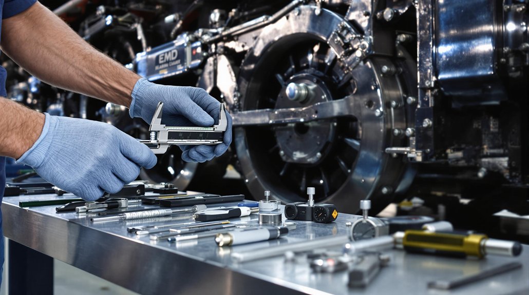
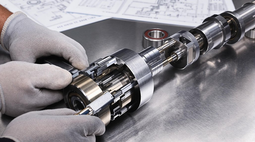
What Does WABCO Locomotive Exhauster Installation Actually Require?

What Does WABCO Locomotive Exhauster Installation Actually Require?

WABCO locomotive exhauster installation requires strict energy isolation protocols, precise bearing inspection, and proper system integration. You’ll need to verify journal integrity using magnetic particle testing and maintain pressure stability between 130-145 PSI. Mount components with vibration-resistant brackets, implement proper grounding with resistance under 0.0025 Ohms DC, and guarantee filtration systems use 250 μm mesh filters. Following these specifications prevents costly downtime and extends component lifespan.

Key Takeaways

  • Proper mounting using steel brackets to prevent vibration-induced failures and ensure proper drainage orientation.
  • Installation of 250 μm mesh filters with high pleat counts to maintain system integrity and prevent contaminants.
  • Implementation of thorough electrical grounding with copper/copper alloy straps meeting resistance thresholds of ≤0.0025 Ohms DC.
  • Calibration of compressors and pressure regulators to maintain 130-145 PSI in main reservoirs.
  • Verification of unloader systems that properly redirect excess compressed air through exhaust ports via check valves.

Lockout/Tagout Safety Protocols for Exhauster Installation

lockout tagout installation safety protocols

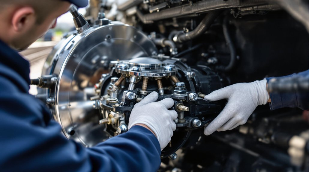
When installing WABCO locomotive exhausters, you must implement thorough lockout/tagout protocols to prevent hazardous energy release. Begin by identifying all energy sources specific to your exhauster system, including electrical, pneumatic, and stored energy components.

Your lockout procedures should prioritize bolt-cutters-resistant devices wherever possible. When lockout isn’t feasible, apply non-reusable tags with your identifier using nylon ties at power sources. These tags must clearly warn against energization hazards.

Always prioritize bolt-cutters-resistant lockout devices; when impossible, use identified non-reusable tags that clearly communicate energization dangers.

Tagout effectiveness depends on proper verification of complete energy isolation. Use voltmeters and pressure checks to confirm all energy has been dissipated before commencing work. Remember that stored energy in air pressure systems and electrical capacitors must be completely released.

Only authorized personnel who’ve completed specific training should execute these protocols. They must understand both one-time and perpetual energy sources relevant to exhauster systems and follow documented step-by-step procedures throughout the installation process. Before returning the locomotive exhauster to service, ensure that all parts and tools are reinstalled and the work area is thoroughly inspected for non-essential items.

Crankshaft Journal and Bearing Inspection Requirements

crankshaft journal inspection guidelines

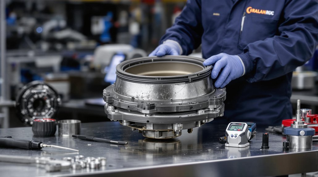
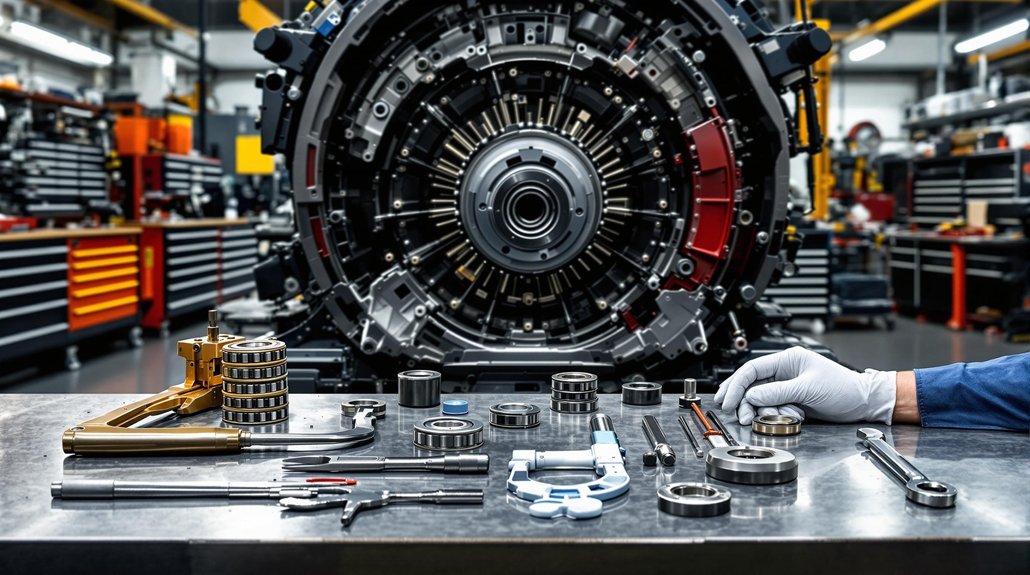
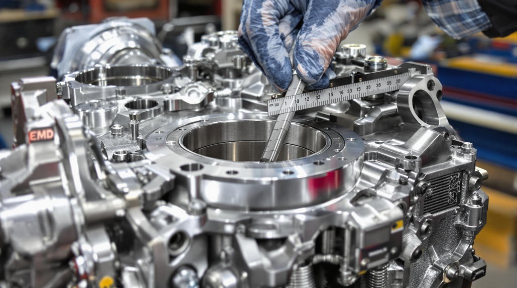
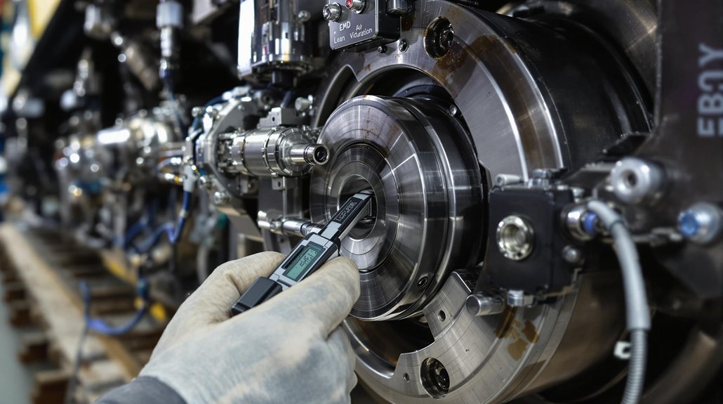
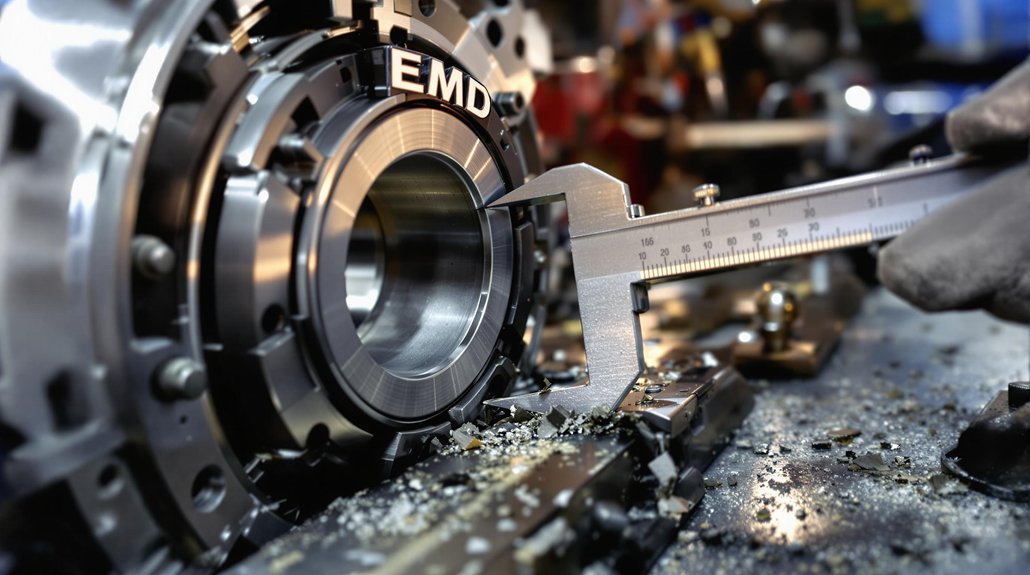
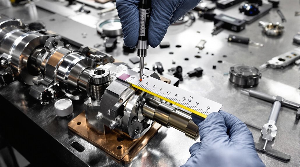
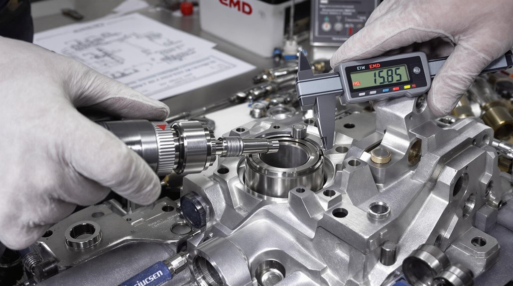
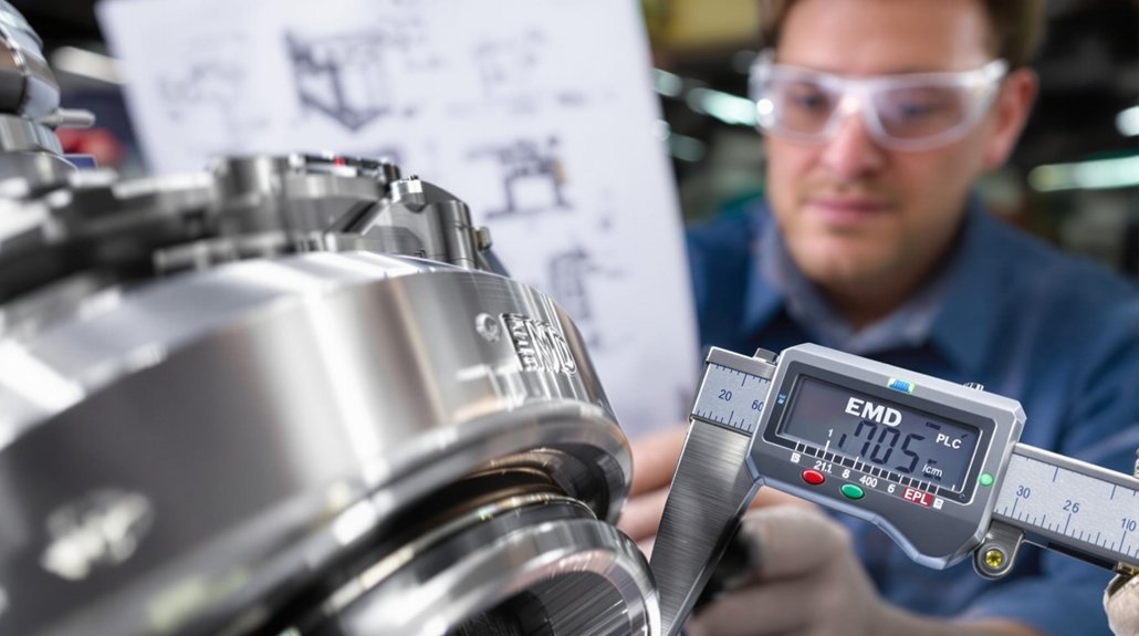
You must thoroughly inspect journal fillets for cracks, scoring, or stress concentrations using magnetic particle testing before exhauster installation. Check all bearing surfaces for abnormal wear patterns, scoring marks, or improper oil clearances using a calibrated micrometer to guarantee measurements fall within 0.001″-0.003″ tolerance. Document your findings on the approved inspection form, noting any deviations from manufacturer specifications that would require journal grinding or bearing replacement. For accurate evaluation, measure both around and along the journals to identify any taper or roundness issues that could affect performance.

Journal Fillet Integrity

Proper maintenance of journal fillet integrity remains essential for maximizing crankshaft service life and preventing catastrophic engine failure. During journal inspection, you must carefully examine these changeover areas for any scratches, erosion, or fretting that could disrupt lubrication patterns or create stress concentration points.

Pay close attention to fillet radii preservation when journals are regrinding, as improper machining compromises their stress distribution function in high-load zones. You’ll need to disqualify any bearings showing heat-induced damage or discoloration, as these thermal distortions greatly reduce operational reliability.

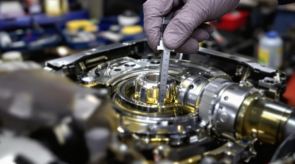
Use an outside micrometer to verify roundness at multiple points around each journal. Measure wear rates, targeting less than 0.01 mm per 10,000 hours of operation. Higher rates demand immediate intervention before fillet integrity becomes compromised beyond salvageable conditions.

Bearing Wear Assessment

Bearing wear assessment follows naturally from journal fillet inspections, as both contribute to locomotive reliability. You’ll need to conduct regular bearing clearance checks according to maintenance intervals, with acceptable wear rates not exceeding 0.01 mm per 10,000 operating hours under normal conditions. According to standard practices, proper movement restrictions must be implemented when bearings show signs of excessive wear to prevent unsafe operation.

Assessment MethodThresholdAction Required
Micrometer measurement>0.01 mm deviationReplacement
Magnetic particle testingAny subsurface crackImmediate replacement
Dial gauge check>0.04-0.06 mm runoutCrankshaft grinding
Oil analysisContamination presentLubricant replacement

Your wear monitoring program should include BWM systems for real-time tracking. Non-destructive loosening of main bearing caps is preferred during inspections. Remember that overheated bearings must be automatically disqualified regardless of measured wear, as thermal damage compromises structural integrity.

Press-Fit Bearing Extraction and Alignment Techniques

bearing extraction and alignment

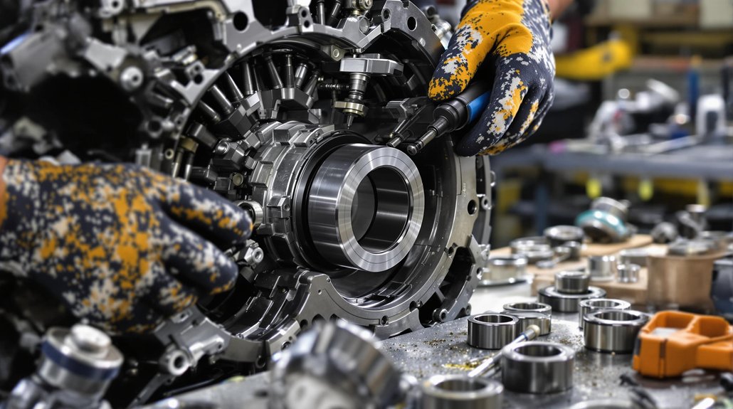
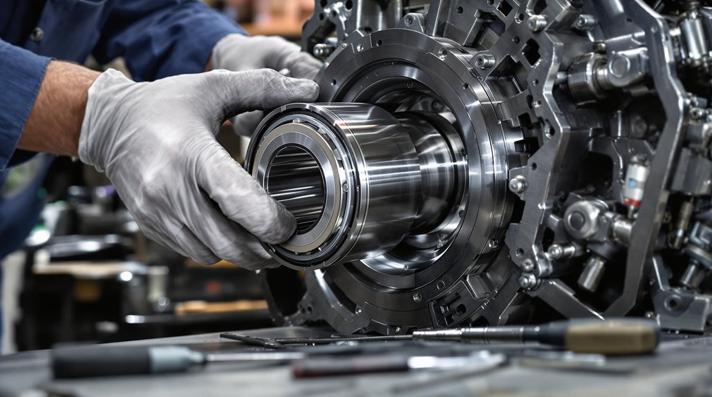
When addressing locomotive exhauster press-fit bearing challenges, technicians must employ systematic extraction and alignment techniques to secure operational integrity. Your bearing extraction options include hydraulic demount presses capable of applying 63.5 metric tons of force with 2-minute cycle times, thermal expansion methods using heated oil or induction coils (maintaining temperatures below 200°C), and mechanical tooling with soft metal casings to protect inner rings. Excessive interference between components can lead to plastic deformation and compromise the structural integrity of the assembly.

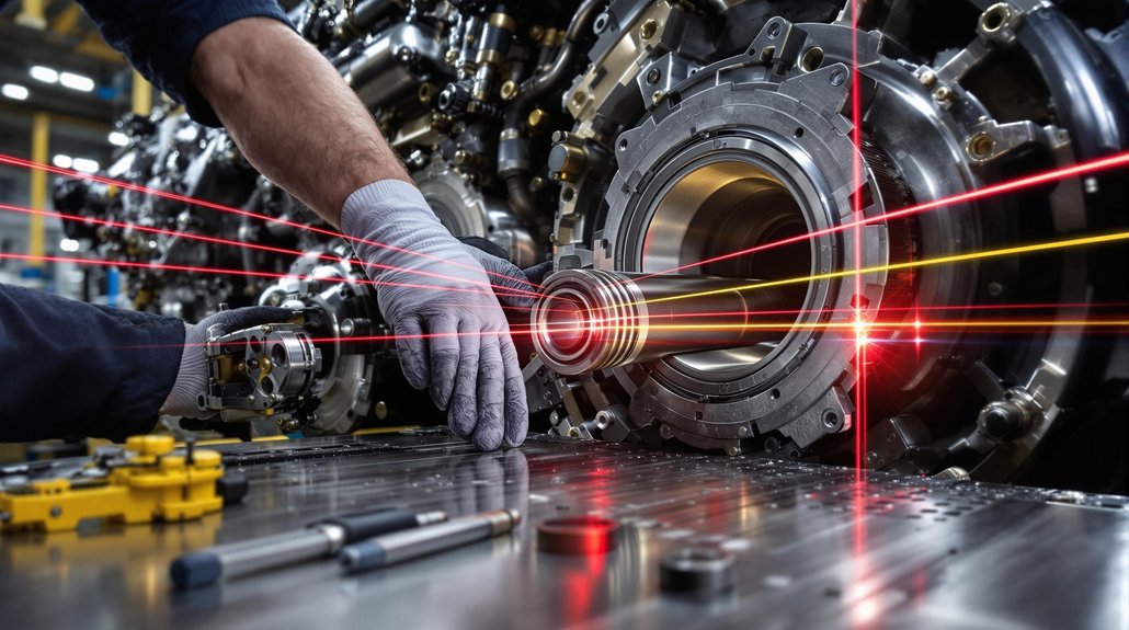
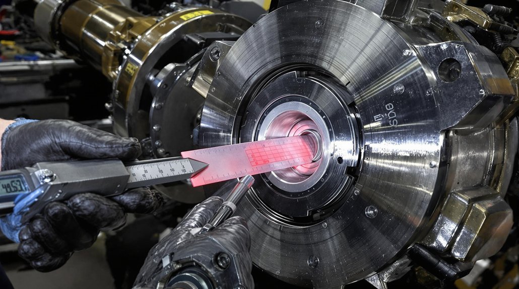
After extraction, proper alignment verification becomes critical. You’ll need to perform dimensional tolerancing through calibrated mandrels matching AAR standards and measure bearing clearances post-installation. Check radial alignment via dial indicators and verify bearing backing ring geometry. Structural validation requires axle journal surface roughness testing and concentricity checks via TIR measurements.

For larger bearings, hydraulic equipment with 432mm press stroke capabilities and 227-liter reservoir systems will guarantee sufficient force application while maintaining the precise control required for WABCO exhauster components.

Air Pressure System Integration and Filtration Standards

air system filtration standards

When installing the WABCO locomotive exhauster, you’ll need to position filters with 250 μm mesh at specific junctures to maintain system integrity and prevent contaminant migration. You must calibrate the compressors and expressors to accommodate flow rates up to 236 SCFM, ensuring ideal pressure regulation throughout the braking cycle. The borosilicate coalescing filters require strategic placement before the twin-tower desiccant systems to trap oil aerosols and extend the operational lifespan of your air dryer components. Proper alignment and secure attachment of all components will maximize performance and longevity of the exhauster system in demanding locomotive conditions.

Filter Placement Essentials

Proper filter placement within WABCO locomotive exhauster systems constitutes a critical element of successful air pressure system integration. Your filter positioning greatly impacts system efficiency and compliance with FRA mandates under 49 CFR Part 229. When installing filtration components, you’ll need to align them with natural airflow paths to minimize turbulence and pressure drops while maximizing contaminant capture. Selecting filters with high filtration efficiency ensures only clean air enters system components, protecting against premature wear.

  • Position primary filters upstream of compressors to protect internal components from abrasive particulates
  • Mount filter housings in accessible exterior compartments for simplified maintenance without system disassembly
  • Implement pressure port provisions for performance monitoring without dismantling the system

For peak airflow optimization, verify your pleated media filters feature high pleat counts that balance restriction and filtration capacity. Secure all components in tamper-proof enclosures with tight seals to prevent bypass contamination that could compromise your locomotive’s pneumatic system integrity.

Pressure System Flow Management

Effective pressure system flow management forms the foundation of reliable locomotive operation, requiring precise integration of air pressure components with appropriate filtration standards.

You’ll need to maintain your system’s pressure stability between 130-145 PSI in main reservoirs, guaranteeing compressor governors are calibrated to prevent exceeding safety thresholds. Install pressure gauges at critical monitoring points to detect anomalies before they cause operational failures. For freight operations, maintain the industry standard brake pipe pressure of 75 PSI while passenger trains require higher settings.

Your filtration system must include air dryers and oil separators to remove moisture, contaminants, and hydrocarbons that could compromise pneumatic components. Regular testing of air quality prevents condensation and potential ice formation during cold-weather operation.

To achieve flow consistency, your condensate collectors and reservoirs must be properly sized to regulate air supply during varying demand. Remember that brake pipe pressure should remain within 15 PSI of regulating valve settings during testing to guarantee reliable performance.

Critical Mounting Specifications for ECU and Air Tanks

The success of WABCO locomotive exhauster systems hinges on precise placement and mounting of ECU components and air tanks. You’ll need to implement proper mounting techniques that guarantee alignment while preventing vibration-induced failures. Always follow manufacturer torque specifications using calibrated tools to achieve the best fastener tension.

Critical Mounting Specifications for ECU and Air Tanks

Air tank positioning requires strategic consideration for efficient compression cycles and minimal airflow resistance. Your ECU mounting must include vibration control measures to maintain signal integrity in the harsh locomotive environment.

Strategic air tank placement optimizes compression cycles, while proper ECU mounting protects signal integrity in demanding locomotive environments.

  • Use steel brackets for high-stress mounting points to withstand operational loads
  • Confirm drainage systems are properly oriented to prevent moisture accumulation
  • Maintain specified clearances for maintenance access per installation manuals

Post-installation verification is critical—conduct pressure tests, alignment checks, and electrical continuity verification before commissioning. Proper documentation guarantees consistency for future maintenance interventions and supports troubleshooting efforts.

Electrical Grounding Requirements for Noise Reduction

Electrical grounding systems represent a foundational component of WABCO exhauster installations, extending beyond basic mechanical mounting considerations. You’ll need to implement precise grounding techniques to guarantee both safety and operational efficiency.

Electrical Grounding Requirements for Noise Reduction

For shock-mounted equipment, copper/copper alloy straps are required to maintain continuity. All bonding connections must meet strict resistance thresholds: ≤0.0025 Ohms DC and ≤0.025 Ohms AC at 150kHz. These specifications are critical for noise mitigation in sensitive control circuits.

Prepare grounding pads with unpainted copper surfaces and secure them via silver soldering or brazing. Circuit isolation from the mechanical structure is mandatory except for EMI and transient absorption components. Industry standards recommend maintaining a maximum resistance value of 5 ohms or less for these large locomotive systems.

When connecting multiple systems, maintain separation between traction and communications grounds, with the latter requiring an independent 5 Ohm system. Post-installation testing is essential to verify all resistance thresholds are met, particularly in configurations where bearing currents might develop.

Unloader Operation and Pressure Regulation Mechanics

pneumatic pressure regulation mechanics

Precision-engineered to maintain ideal pressure levels throughout the pneumatic system, WABCO exhauster unloaders function as automated regulation valves that cycle between cut-in and cut-out thresholds. You’ll find these components feature a five-port configuration integrating critical pressure management pathways for inlet, outlet, pilot control, regulation, and exhaust functions.

Unloader functionality hinges on a sequence of pressure-triggered events that protect your locomotive’s pneumatic integrity:

  • Monitors system pressure continuously, activating at cut-out threshold (typically 117.48 psi)
  • Redirects excess compressed air through the exhaust port while securing stored pressure via integrated check valves
  • Automatically resets when pressure drops to cut-in level, enabling system recharging

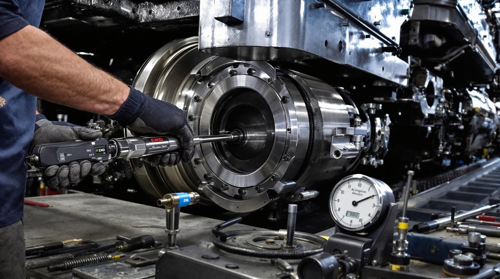
During installation, verify proper alignment with intercooler systems and confirm all connections meet torque specifications. The unloader’s dual-chamber design with spring-loaded pistons requires precise positioning to coordinate effectively with compressor control switches during load/regeneration cycles. A pressure gauge connected to Port 22 or 4 is essential for accurate calibration during installation.

Component Material Selection and Thermal Considerations

material durability and thermal management

Selecting appropriate materials for WABCO locomotive exhauster components represents a foundational engineering requirement that directly impacts operational reliability and system longevity. You’ll need to prioritize high-grade materials capable of withstanding the harsh operating conditions while ensuring proper thermal management through specialized components.

Your material durability considerations must include verification of load ratings that match operational stress patterns, particularly for components like crankshaft journals and compressor pistons requiring heat-resistant alloys. These materials must maintain precise dimensional tolerances while enduring pressures up to 140 psi.

For effective thermal management, implement double-pass intercoolers and plate-style configurations that optimize airflow and dissipate heat efficiently. Safety valve installations regulate system pressure, preventing overheating during operation. The removal of main bearings should proceed in sequence from the flywheel end forward to minimize stress on the crankshaft during maintenance operations. Additionally, air dryer systems mitigate moisture-related thermal expansion risks that could compromise system integrity.

Regular inspection of wear patterns on critical surfaces helps identify thermal stress points before they lead to component failure.

Frequently Asked Questions

Like a fine watch requiring precise calibration, your new WABCO exhausters don’t have a specifically defined break-in period in the documentation. You’ll need to conduct extended operational testing under controlled conditions. Follow installation guidelines meticulously to guarantee proper exhauster performance. Break-in procedures typically involve monitoring performance metrics during initial operation cycles while adhering to the mounting, pressure, and structural protocols outlined in the technical specifications.

Can WABCO Exhausters Be Retrofitted to Non-Wabco Locomotive Systems?

Retrofitting WABCO exhausters to non-WABCO systems is technically possible but presents significant compatibility challenges. You’ll face proprietary component issues, including specific part numbers and mounting brackets that require precise dimensions. Retrofit considerations must address thread sealing compliance, electrical grounding requirements (<10 ohms resistance), and control line filter positioning. You’ll need to modify valve bracket orientation for vertical alignment and guarantee your system can accommodate WABCO’s strict contamination protocols and specialized tooling requirements.

What’s the Average Lifespan of Exhauster Bearings Under Normal Conditions?

Under normal operating conditions, your exhauster bearings typically last 7,000-10,000 service hours. You’ll maximize this lifespan through rigorous bearing maintenance, including ultrasonic cleaning after 2,500 hours. Follow manufacturer-recommended lubrication schedules—typically every 1,000 hours with high-grade lubricant. Monitor for vibration patterns exceeding 0.005″ tolerance with dial indicators. Replace immediately if you detect persistent vibration or when play measurements approach manufacturer-specified limits.

Are Aftermarket Components Compatible With OEM WABCO Exhauster Installations?

Like a chain that’s only as strong as its weakest link, your WABCO exhauster system demands careful component selection. Aftermarket components must meet stringent OEM specifications, including dimensional accuracy, material standards, and pressure ratings. You’ll need to verify thread compatibility, bearing tolerances, and surface finish requirements. Critical factors include proper thread sealant application and validation of torque specifications to maintain system integrity. Aftermarket quality varies greatly; always confirm component compatibility before installation.

What Temperature Fluctuations Can WABCO Exhausters Safely Withstand?

WABCO exhausters demonstrate robust temperature tolerance within a moderate operational range. You’ll find these units can withstand temperature fluctuations between the 1040-1080 series steel components’ design parameters. For ideal exhauster durability, maintain operating temperatures below the 150°C threshold during maintenance procedures. Critical components like unloader diaphragms, springs, and check valves are specifically engineered to maintain reliability through thermal cycling that occurs during compression and exhaust phases.

WABCO Crankshaft Compressor Exhauster: Technical Specifications Guide

WABCO Crankshaft Compressor Exhauster: Technical Specifications Guide

WABCO Crankshaft Compressor Exhausters deliver high-performance in compact designs. Single-cylinder models (232×205×325mm, 7.5kg) operate at 145psi, while twin-cylinder variants (317×170×330mm, 20.2kg) offer increased capacity. You’ll find M20×1.5 threaded connections for seamless integration, with water-cooling technology eliminating bulky radiators. All units feature high-molybdenum alloy construction for -40°C to +80°C operation. The technical specifications below reveal how these precision-engineered components maintain performance under extreme conditions.

Key Takeaways

  • Single-cylinder compressors measure 232 × 205 × 325 mm and weigh 7.456 kg, while twin-cylinder variants are 317 × 170 × 330 mm and 20.24 kg.
  • WABCO compressors operate at pressures of 115-145 psi, with specialized arctic variants maintaining performance up to 6,000 psi.
  • Standard M20 × 1.5 threaded connections ensure easy engine integration, with M18 × 1.5 threads available for backward compatibility.
  • Water-cooling technology eliminates bulky radiators, while CDP-coated variants reduce operational temperatures by 15-20°F.
  • Maintenance requires bearing inspections every 90 days, air filter replacement every 1,500 hours, and weekly audits for scoring patterns.

Design Dimensions and Space Efficiency

space efficient compressor design

WABCO crankshaft compressor exhausters showcase remarkable space efficiency through precise dimensioning and strategic material selection. Single-cylinder models measure 232 × 205 × 325 mm, weighing just 7.456 kg, while twin-cylinder variants maintain spatial optimization at 317 × 170 × 330 mm despite their 20.24 kg mass.

The design efficiency stems from aluminum alloy construction in single-cylinder units, complemented by stainless steel components in critical areas like reed valves and pistons. You’ll find standardized M20 × 1.5 threaded crankshaft connections that simplify engine integration through flange mounting.

Water-cooling technology further reduces the footprint by eliminating bulky radiators, while the simplified valve plate design minimizes assembly complexity. The compact connecting rod configuration optimizes stroke/bore ratios, enhancing performance without sacrificing space. Lightweight fasteners including snap rings and M8×80 hexagonal bolts contribute to the overall space-saving approach, making these units ideal for constrained installations.

Pressure Rating and Operational Thresholds

pressure stability in extremes

WABCO compressor exhausters operate within a spectrum of pressure thresholds, from 145 psi in single-cylinder models to specialized arctic variants maintaining 6,000 psi in extreme conditions. You’ll find that temperature directly impacts pressure performance, with the units reliably functioning across an impressive -40°C to +80°C range while CDP-coated variants reduce operational temperatures by 15-20°F under load. Your compressor’s pressure stability is further enhanced through integrated thermal management systems that maintain consistent performance even at peak operational thresholds. For cold-weather applications, the high-molybdenum alloy construction ensures pressure-compensated lubrication remains at ideal viscosity despite extreme temperature fluctuations.

Maximum Operating Pressures

Four critical pressure thresholds define the operational parameters of WABCO crankshaft compressor exhausters across various models. Standard single-cylinder units operate efficiently up to 8 bar (115 psi), while specialized engine-driven shaft assemblies can achieve peak pressures of 145 psi with enhanced compression efficiency.

You’ll find dual-cylinder assemblies maintain pressure uniformity through high-strength steel alloys that distribute loads effectively across the 636 cm³ swept volume capacity. For extreme environments, arctic-grade models deliver consistent pressures up to 6,000 PSI (413 bar) through high-molybdenum alloy construction.

Material considerations remain paramount across all pressure ratings, with CDP-coated crankshafts withstanding loads up to 180,000 PSI (1,243 bar). Cross-compatible M18 x 1.5 thread patterns guarantee pressure handling capabilities remain consistent when retrofitting or upgrading existing systems. Regular inspection of oil hole edges helps prevent fatigue failure that can compromise pressure containment integrity.

Temperature-Pressure Relationship

The relationship between temperature and pressure forms an integral dynamic within WABCO crankshaft compressors, directly impacting operational thresholds and system longevity. You’ll need to maintain discharge temperatures below 204°C during operation while ensuring inlet temperatures don’t exceed 110°C for more than 30 minutes to preserve temperature stability.

  • Maximum coolant pressure testing should never exceed 12 bar to prevent system damage
  • Pressure fluctuations between compressor and unloader valve indicate restricted lines requiring replacement
  • Oil circulation through crankshaft passages serves dual functions of lubrication and thermal regulation
  • Radial oil patterns signal overload conditions that compromise pressure integrity

When troubleshooting, always check for pressure differentials before replacing components, as blockages often manifest before mechanical failure. The air dryer inlet temperature must remain below 71°C to maintain system efficiency. Proper attention to safety precautions during maintenance procedures is essential to prevent accidents when working with pressurized systems.

Material Composition and Corrosion Resistance

corrosion resistant high molybdenum alloys

WABCO crankshafts employ cathodic dip painting (CDP) technology that markedly reduces exposure to corrosive agents while maintaining thermal efficiency. The high-molybdenum alloys in arctic-grade designs provide superior strength (up to 180,000 psi load capacity) and corrosion resistance in extreme temperatures without compromising structural integrity. You’ll find these materials undergo rigorous environmental durability testing to guarantee consistent performance across varying humidity levels, temperature fluctuations, and mechanical stress conditions.

CDP Coating Technology

Advanced material engineering defines CDP coating technology, which utilizes NiCrBSi alloy layers reinforced with tungsten carbide through specialized application methods including arc welding, vacuum fusion, and laser powder coating. This composite structure features 35% WC in a NiCrBSi matrix applied to steel substrates, creating exceptional wear resistance for critical compressor components.

  • Fully automatic application guarantees uniform thickness without irregularities
  • Weldable steel substrates enable post-coating modifications without compromising protection
  • Multi-component additives create hybrid structures with optimized mechanical properties
  • Controlled fusion processes maintain full mechanical integrity of base alloys

The coating applications extend beyond mere surface protection, functioning as an integrated system. The specialized formulation creates a physical barrier against corrosive environments while maintaining structural integrity under demanding operational conditions. The cataphoresis (CDP) process, developed continuously for the automotive industry, significantly increases service life and overall product value by preventing oxidation of metal components.

Alloy Strength Benefits

Material engineering excellence underpins WABCO crankshaft compressors through strategic alloy selection that maximizes operational durability. SAE 1045 steel delivers uniform tensile strength up to 180,000 psi while providing superior vibration reduction that extends service life in demanding applications.

The alloy durability advantages are particularly evident in extreme environments. High-molybdenum enhancements inhibit oxidation and corrosion even in arctic conditions, while maintaining consistent pressure transmission capabilities. This molybdenum content improves both corrosion resistance and high-temperature stability.

You’ll benefit from the precision-bore alignment that reduces maintenance requirements by 50% through minimized vibration. Thread configurations (M18, M20, and M22 x 1.5) guarantee cross-model compatibility for simplified inventory management. The optimized thermal conductivity prevents heat-related material fatigue that would otherwise accelerate component degradation.

Environmental Durability Testing

Through rigorous environmental durability protocols, SAE 1045 steel crankshafts undergo extensive testing that validates their exceptional performance under extreme conditions. Your compressor’s reliability is guaranteed through load testing exceeding 180,000 psi—verifying material integrity under high-pressure operations across diverse environments.

  • CDP coating technology provides superior protection while handling extreme pressures in variable conditions
  • 20mm crankpin diameters deliver measurable vibration reduction, preventing material fatigue
  • High-molybdenum alloy variants maintain 6000 PSI pressure stability at temperatures as low as -40°C
  • M18 x 1.5 thread patterns guarantee cross-compatibility without compromising structural integrity

Water-cooled systems with M20 x 1.5 threading further enhance durability by reducing thermal stress. These precisely engineered components work together to guarantee maximum longevity in the harshest operating environments.

Arctic Performance and Extreme Weather Capabilities

arctic resilience in performance

While extreme weather conditions present considerable challenges for pneumatic systems, WABCO’s Crankshaft Compressor Exhauster demonstrates exceptional resilience in Arctic environments with its operational temperature range of -40°C to +105°C. This arctic resilience is engineered into every component, from the Twin-Cylinder design that maintains consistent output to the specialized water-cooling system that effectively manages heat fluctuations.

You’ll find extreme efficiency even in confined Arctic vehicles, thanks to its compact dimensions (317x170x330mm). The 3000 RPM operating speed ensures reliable cold-weather performance by maintaining sufficient airflow despite viscous air resistance. The engine-supplied lubrication system considerably reduces wear in low-temperature conditions where standard lubricants might fail.

Critical to its performance is the thermal management system featuring balanced copper-contact cooling for even temperature distribution. Cold-tolerant sealing materials maintain compression integrity while the robust materials resist corrosion in the challenging humidity cycles typical of Arctic operations.

Maintenance Requirements and Service Intervals

structured maintenance service intervals

Proper maintenance of the WABCO Crankshaft Compressor Exhauster demands structured adherence to established service intervals for peak performance and longevity. Your maintenance schedule must account for environmental factors, with high-humidity environments requiring bearing inspections every 90 days instead of the standard 180-day interval.

Key service intervals include:

  • Journal fillet inspections every 6 months using micrometers to detect out-of-round conditions exceeding 0.005″
  • Air filter replacement every 1,500 operational hours or during oil changes
  • Engine oil changes aligned with vehicle manufacturer schedules
  • Weekly visual audits for scoring patterns on articulated surfaces

Documentation in maintenance logs enables predictive maintenance timing. You’ll achieve ideal rebuild intervals (typically 5-7 years) using OEM components, while aftermarket alternatives may reduce service life by 20-30%. During maintenance inspections, thermal scanning identifies early bearing degradation, particularly critical in humid operational environments.

Thread Configuration and Cross-Model Compatibility

thread standardization ensures compatibility

The standardization of thread configurations across WABCO Crankshaft Compressor Exhausters represents a foundational aspect of their design that extends beyond routine maintenance considerations. The dominant M20 x 1.5 thread specification enables seamless integration across single, dual, and triple-cylinder models, facilitating thread compatibility between different system architectures.

For legacy installations, M18 x 1.5 threads provide backward compatibility while supporting high-torque applications. This standardization is particularly evident in dual-cylinder (636 cm³) and triple-cylinder units, where identical thread patterns enable model interchangeability without specialized tooling.

When cross-referencing parts like 9121400320 (single-cylinder) and 912510303A (triple-cylinder), you’ll find consistent thread specifications that simplify inventory management. RENAULT cross-references (e.g., 22062019 for WABCO 9125140090) further extend compatibility with third-party systems, while maintaining the material integrity necessary for operating pressures ranging from 145 psi in single-cylinder to 203.1 psi in twin-cylinder configurations.

Thermal Management and Temperature Control Systems

optimized thermal management solutions

Effective thermal management within WABCO Crankshaft Compressor Exhausters relies on sophisticated water-cooled systems that maintain operational integrity across varying load conditions. These thermal efficiency solutions employ precision-bore alignment technology that reduces maintenance needs by 50% while preserving ideal cooling paths.

WABCO’s thermal management excellence delivers 50% less maintenance while maintaining optimal cooling efficiency throughout demanding operational cycles.

You’ll find WABCO’s cooling innovations particularly evident in:

  • CDP-coated crankshafts that reduce operating temperatures by 15-20°F while extending component durability
  • Integrated water channels providing uniform cooling across pistons and connecting rods
  • Direct crankshaft lubrication systems that synchronize with engine RPM for thermal stability
  • Arctic-grade alloys capable of maintaining consistency from -40°F to 6000 PSI

For maximum performance, single-cylinder compressors achieve 145 psi while twin-cylinder models reach 203.1 psi using flange-mounted cooling systems. The high-molybdenum alloys withstand metallurgical stress during thermal cycles, ensuring your system maintains structural integrity even during prolonged heat exposure.

Dual vs. Single Cylinder Performance Metrics

dual cylinder performance advantage

Comparing dual and single cylinder configurations reveals substantial performance differences that directly impact your operational capabilities and system requirements. The dual cylinder design delivers superior performance efficiency with 636 cm³ swept volume compared to the single’s estimated 150 cm³. This volumetric advantage, combined with higher operating speeds (3000 RPM vs. 2600 RPM), markedly increases air delivery capacity.

While single cylinders can achieve higher maximum pressures (up to 261 psi in high-pressure variants versus the dual’s consistent 203.1 psi), they exhibit greater variation between models. The dual cylinder design features a larger 3.35″ piston diameter and 2.20″ stroke, optimized for continuous high-performance operation. You’ll find the dual configuration heavier (20.24 kg) with engine-supplied lubrication and flange mounting, while the single cylinder offers advantages in weight, footprint, and flexible foot mounting options.

Frequently Asked Questions

Can the Crankshaft Be Retrofitted to Older Non-Wabco Systems?

While exploring retrofit compatibility options, you’ll find significant challenges. You can’t practically retrofit WABCO crankshafts into non-WABCO systems due to incompatible thread configurations, specialized alloys, and mismatched bearing tolerances. Performance enhancements would require custom adapters, specialized fabrication, and extensive modifications exceeding 50% of new system costs. The required precision-bore technology and pressure-handling capabilities simply don’t align. Professional WABCO-authorized specialists offer your only viable, though limited, integration pathway.

What Is the Expected Lifespan Under Heavy-Duty Cycle Operations?

Under heavy-duty maintenance conditions, you’ll achieve 5-7 years of operational lifespan when following proper protocols. This benchmark assumes regular lubrication, monthly inspections, and timely filter replacements. Lifespan factors include alignment precision, thermal management through CDP coatings, and load balancing. High-molybdenum alloys in arctic grades extend performance in extreme temperatures, but require more vigilant maintenance. Rebuilding within the recommended window prevents catastrophic failures and extends service life.

Does Operation at Higher Altitudes Affect Performance Specifications?

Yes, higher altitudes markedly impact your compressor’s performance metrics. You’ll experience reduced volumetric efficiency due to lower air density, requiring altitude adjustments to maintain output. Your system will demand increased RPM to achieve target pressures with decreases of approximately 3% per 1,000 feet elevation. Precision-bore alignment technology becomes essential as reduced intake pressures strain suction valves. Monitor oil consumption more frequently as altitude-induced stratification can occur.

Are Replacement Parts Available for Discontinued Compressor Models?

Absolutely countless replacement options exist for your discontinued compressor models. You’ll find remanufactured solutions requiring core returns, aftermarket alternatives with direct replacement capabilities, and repair kits for targeted fixes. These options match OEM specifications while providing cost efficiency. When ordering, verify compatibility through cross-reference numbers. Most replacements require core exchange, with damaged/non-returned cores incurring surcharges of approximately €175-180. Extensive catalogs detail housing, valve and seal assemblies for precise maintenance.

How Does Salt-Water Exposure Impact the Cdp-Coating Longevity?

Salt-water exposure considerably compromises CDP-coating’s longevity through accelerated corrosion mechanisms. Your coating’s corrosion resistance decreases as salt solubility increases with temperature, forming conductive electrolytes that promote galvanic corrosion. While CDP offers 1,000+ hours of salt-spray resistance, continuous exposure rapidly degrades this protection. Implement proactive maintenance practices including routine inspections for coating integrity and immediate repair of scratches to prevent salt penetration through micro-defects in the phosphate barrier.

5 WABCO Locomotive Compressor Crankshaft Repair Tips

5 WABCO Locomotive Compressor Crankshaft Repair Tips

When repairing WABCO locomotive compressor crankshafts, you’ll need to: use proper lifting equipment rated for 400+ lbs, position the crankcase vertically for safe extraction, measure journals with micro-calipers to guarantee tolerances under 0.003″, apply correct torque sequences when replacing bearings, and validate repairs by checking straightness to a maximum 0.002″ deviation. Proper lubrication with compatible oils like Rocol 1000 will extend the service life of your newly repaired components.

Key Takeaways

  • Store crankshafts horizontally after removal to maintain bearing integrity and prevent shaft distortion over time.
  • Ensure main journal measurements don’t exceed 0.003″ for combined taper and out-of-round conditions for proper operation.
  • Use lifting equipment rated for 400+ lbs when removing or installing WABCO locomotive compressor crankshafts.
  • Apply Rocol 1000 lubricant specifically formulated for WABCO systems to ensure proper component protection.
  • Verify crankshaft straightness to maximum 0.002″ deviation during post-repair validation for optimal performance.

Proper Crankshaft Removal and Handling Procedures

crankshaft removal safety procedures

When approaching crankshaft removal in WABCO locomotive compressors, proper preparation is essential for both safety and component integrity. You’ll need heavy-duty lifting equipment capable of managing at least 400 lbs, with additional crankshaft support structures in place before beginning extraction.

Position the crankcase axis vertically for safe removal, and guarantee your work environment is clean to prevent contamination. Begin by removing connecting rod caps while maintaining piston alignment, then detach the main bearing plate using hex cap screws. Use precision bushing drivers and crankshaft bearing pullers for careful extraction without damage. After removal, turn the compressor upside down to better access the critical components in the crank case.

Apply mild solvents to prepare surfaces and use a soft mallet to gently tap out the front cover. Keep disassembly tools organized in marked trays to track small components. After removal, store the crankshaft horizontally to prevent bearing collapse and immediately inspect for wear patterns before sealing all bores.

Critical Dimensional Inspection Techniques

dimensional inspection techniques overview

After properly removing and storing the crankshaft, your next key responsibility involves performing thorough dimensional inspection techniques. Measure main and rod journals using a micro-caliper, ensuring they remain within manufacturer-specified journal tolerances. Remember that combined taper and out-of-round conditions shouldn’t exceed 0.003″.

Conduct fillet inspections to verify proper radius compliance (0.130-0.160″ for inline, 0.100-0.130″ for V-types). These changes must remain smooth without sharp edges that could create stress concentration points. Regular measurements are particularly important for larger engines with bore over 250 mm to prevent serious damage to bearings and other critical components.

Inspection AreaMeasurement MethodAcceptance Criteria
Main JournalsMicro-caliper at 90° intervalsWithin OEM tolerance range
Rod JournalsCross-pattern measurement≤0.003″ taper + out-of-round
Fillet RadiiTemplate comparisonNo sharp edges or changes

Don’t forget to bar the engine at specified positions (BDC, 90° intervals) to check web-to-web deflection. Document all measurements for trend analysis during future maintenance cycles.
Bearing and Connecting Rod Replacement Best Practices

bearing replacement best practices

Bearing and connecting rod replacement demands meticulous attention to guarantee locomotive compressor reliability and longevity. When replacing these vital components, you’ll need to use a lifting mechanism rated for at least 400 pounds during crankshaft removal and installation.

Secure the crankcase vertically before extracting the crankshaft, and remove bearing plates using the hex head cap screws. During reassembly, proper bearing alignment is essential—ensure bearing plates align correctly with the crankcase. Check rod clearance by verifying that all sliding leaves’ holes properly align over the cylinder head pins. Using equivalent specifications that match the original parts in dimensions, strength, and material is critical for preventing failures or injuries.

Always clean surfaces thoroughly with mineral spirits, avoiding materials that leave lint. Apply light engine oil to sliding leafs for proper function. Follow the specified torque sequence (1-2-3-4) for mounting bolts to distribute pressure uniformly. For cylinder head bolts, apply 18.5 lb-ft ±2.5 followed by an additional 90° rotation using an angular gauge for precise torque alignment.

Ensuring Optimal Lubrication System Performance

optimal lubrication maintenance practices

Maintaining ideal lubrication system performance in WABCO locomotive compressors requires strict adherence to manufacturer specifications and regular preventive maintenance. Always use specified compressor lubricants like Rocol 1000 for slide valves to guarantee proper lubricant compatibility with system tolerances.

Monitor oil pressure daily and service filters quarterly to prevent particulate buildup in lubrication circuits. The correct oil viscosity, as recommended by WABCO, maintains thermal stability under operating conditions. Check crankcase oil levels monthly, replacing lubricants during annual overhauls to eliminate contaminants. Maintaining proper lubrication is especially critical in sister locomotives that operate as synchronized pairs and share operational demands.

For peak performance, clean crankcases annually with mineral spirits to remove sludge that obstructs oil circulation. When synthetic oils are used in high-stress applications, you’ll achieve improved thermal stability. After repairs, measure filling times against specifications to confirm adequate circulation. Document maintenance outcomes, particularly oil consumption rates, to track system health and prevent catastrophic failures from inadequate lubrication.

Post-Repair Validation and Testing Protocols

post repair validation protocols

Proper validation and testing of WABCO locomotive compressors following repairs guarantees reliability and compliance with safety standards. Begin with structural integrity verification by measuring crankshaft straightness to a maximum deviation of 0.002″ and checking bearing journals against manufacturer tolerances.

Conduct thorough leak detection using soap suds tests on all compressor surfaces and connections. For Class 1 air brake systems, employ acoustic sensors for advanced detection capabilities. Test pressure buildup against performance benchmarks, ensuring the system reaches cutoff thresholds while maintaining consistent RPM. Ensure the main reservoir pressure maintains 130-145 PSI for optimal compressor operation.

Document all dimensional measurements against tolerance charts and cross-reference results with WABCO validation criteria. Monitor for pressure line blockages and verify cooling water flow in water-cooled systems. Compare post-repair performance with baseline data to confirm restoration of functionality.

Maintain detailed repair logs and submit test reports for compliance certification to meet FRA requirements.

Frequently Asked Questions

Can Crankshafts With Minor Cracks Be Repaired Instead of Replaced?

You can repair crankshafts with superficial microscopic cracks if they’re less than 1% of material thickness and don’t affect crankshaft integrity. However, cracks near journals, oil passages, or counterweights require replacement. Modern repair techniques include magnetic particle testing to verify defect limits. Always demagnetize after inspection. Remember that fatigue-induced cracks typically indicate irreversible stress damage, making replacement the safer choice for long-term reliability.

What’s the Expected Service Life After Proper Crankshaft Reconditioning?

Like a well-tuned orchestra, your properly reconditioned crankshaft can perform reliably for 5-7 years with ideal maintenance practices. Crankshaft longevity depends critically on adherence to scheduled maintenance protocols, operating within specified RPM ranges, and maintaining proper lubrication. You’ll maximize service life by conducting oil inspections every 3 months, ensuring balanced load distribution, and preventing thermal stress through effective cooling system maintenance.

How Do Temperature Fluctuations Affect Crankshaft Clearance Requirements?

Temperature fluctuations directly impact your crankshaft’s clearance requirements through temperature expansion. As temperatures rise, ductile iron expands, reducing concentricity between mating parts. You must account for this growth when establishing bearing gaps, typically requiring 0.001-0.002 mm tolerances. Extreme temperature drops increase clearance gaps, risking component impact. Make clearance adjustments using shim packs during assembly, and verify measurements after the first operational cycle to guarantee proper thermal compensation.

Are Aftermarket Crankshafts Comparable in Quality to OEM Components?

Aftermarket crankshafts can match OEM reliability in some cases but with significant variability. High-tier aftermarket options featuring precision-bore alignment and CDP coatings offer comparable durability at 20-40% cost savings. You’ll find that top aftermarket manufacturers meet OEM standards for load capacity (up to 180,000 psi), but you should verify their testing protocols for thermal/structural stress, as certification transparency often lacks compared to OE-proven components.

When Is It More Economical to Replace Rather Than Repair?

You should replace rather than repair when your cost analysis shows repair expenses exceeding replacement costs. Consider cumulative labor, parts, and downtime expenses in your repair vs replacement decision. Replace when you face irreparable structural damage, safety-critical component failures, or recurring breakdowns. Factor in warranty benefits, operational impacts, and long-term reliability. New components often deliver better predictability and fewer maintenance cycles, making replacement economically sound despite higher upfront costs.

Expert Guide To Rebuilding WABCO Locomotive Exhauster Crankshaft Assemblies

Expert Guide To Rebuilding WABCO Locomotive Exhauster Crankshaft Assemblies

Rebuilding WABCO locomotive exhauster crankshafts requires precision inspection and meticulous attention to tolerances. You’ll need to measure journal diameters with micrometers (0.0005″-0.001″ tolerance), check for scoring or micro-cracks, and verify fillet radius tolerances (+0.005″/-0.002″). Maintain surface finishes between 0.1-0.25 RA using diamond-tipped grinding wheels. Follow torque specifications precisely: 22 ft-lb initial, then 52 ft-lb with 60-degree rotation for connecting rods. The complete restoration process involves several more critical steps.

Key Takeaways

  • Verify journal dimensions using precision micrometers (0.0005″-0.001″ tolerance) and check for out-of-round conditions with dial indicators.
  • Maintain surface finishes between 0.1-0.25 RA using diamond-tipped grinding wheels and implement thermal stress management during machining.
  • Inspect fillet radius tolerances within +0.005″/-0.002″ specifications and re-machine immediately if variances exceed 0.001″.
  • Torque connecting rod assemblies initially to 22 ft-lb for alignment, followed by 52 ft-lb and 60-degree rotation.
  • Ensure main bearing cap torque follows three-step procedure (22 Nm → 45 Nm → 100 Nm) for proper load distribution.

Identifying Signs of Wear and Degradation

crankshaft wear inspection guidelines

A thorough inspection of WABCO locomotive crankshaft assemblies requires systematic evaluation of both visible and performance-related deterioration indicators. When examining the crankshaft, you’ll need to measure main journal and conrod diameters using micrometers to detect deviations from OEM specifications—a primary wear indicator.

Look for out-of-round conditions, uneven bearing contact patterns, and surface pitting that suggest contamination or lubrication failure. Metal-on-metal contact marks indicate critical lubrication bypass issues. Performance decline manifests as reduced power output, unstable RPM readings, and engine misfires.

Monitor oil pressure closely, as low readings accelerate journal wear and can drastically affect maintenance frequency requirements. Abnormal noise such as grinding or knocking often indicates worn-out parts that require immediate attention. Structural deterioration appears as increased bearing clearances and damaged thrust washers. Use dial gauges to check TIR values against manufacturer tolerances, particularly when turntable testing reveals potential alignment issues. Contact pattern analysis should show consistent bearing engagement across wearing surfaces.

Essential Tools and Safety Protocols for Disassembly

disassembly tools and safety

Proper disassembly of WABCO locomotive crankshaft assemblies requires specialized tooling and strict adherence to safety protocols to prevent component damage and workplace injuries.

Disassembling WABCO locomotive crankshafts demands specialized tools and rigorous safety compliance to protect both components and personnel.

You’ll need high-torque impact wrenches for corroded bolts, precision dial calipers for measuring clearances, and dial indicators to verify alignments post-disassembly. The connecting rod converts the piston’s linear motion to rotational movement within the crankshaft assembly. Maintain your tools regularly to guarantee accurate torque wrench calibration and proper functionality.

Always wear full PPE including gloves, safety glasses, and respirator masks when handling components with sharp edges or residual lubricants. Thorough safety training must precede any disassembly work involving hydraulic presses or bridge cranes for heavy components exceeding 100 lbs.

Implement proper pressure relief sequencing before accessing exhauster chambers. Use manufacturer-approved methodologies from WABCO service manuals alongside controlled heating (300-400°F) for sleeve removal. Deploy workspace containment systems with secondary trays and spill kits to manage fluid leakage during the disassembly process.

Critical Component Inspection and Measurement Techniques

journal surface inspection techniques

You’ll need to meticulously evaluate each journal surface for signs of scoring, galling, or micro-cracks using both visual inspection and magnetic particle testing to identify flaws invisible to the naked eye. Verifying dimensional tolerances requires measuring journal diameters at multiple points with a calibrated micrometer, comparing readings against WABCO specifications with particular attention to out-of-round conditions exceeding 0.002″. Document all findings in your inspection report, noting any journals requiring machining, polishing, or replacement based on the severity of wear patterns and deviation from original specifications. Remember to carefully check for proper brake pipe leakage rates to ensure the integrity of the air brake system, as excessive leakage can compromise braking performance.

Journal Surface Evaluation

Journal surfaces represent the crankshaft’s most critical wear interfaces, requiring meticulous evaluation techniques to guarantee locomotive reliability and performance. Your inspection should begin with thorough visual assessment for cracks, scoring, and pitting—indicators of lubrication failure or material fatigue.

During wear assessment, examine journal polishing patterns carefully; abnormal shininess often signals improper loading. Validate journal geometry using precise measurements: maintain taper tolerances of ≤0.0004″ for main journals and ≤0.0002″ for rod journals. Surface irregularities exceeding 0.00118″ out-of-round limit require immediate correction. Remember that the radial wear of connecting rod journals typically forms an elliptical shape due to uneven load distribution during operation.

Pay particular attention to fillet radii integrity and thrust surface condition, as these areas absorb significant operational stress. Complete your evaluation with MPI testing using wet or dry particle methods to detect subsurface defects invisible to the naked eye.

Dimensional Tolerance Verification

Dimensional tolerance verification forms the backbone of any successful crankshaft rebuilding operation, requiring specialized inspection techniques that guarantee compliance with exacting WABCO specifications. Your tolerance assessment must focus on both radial and axial measurements to prevent premature bearing failure. Create a deflection curve by plotting measurements to identify bearings that may need attention based on their position in the system.

ParameterTolerance LimitMeasurement Method
Journal Diameter0.0005″–0.001″Precision micrometer
Out-of-Round≤0.00004″Dial indicator
Taper (Tri-metal)1/10,000th of lengthMulti-point diameter check
Radial Eccentricity0.005 mm maxV-block deflection test
Total Misalignment≤0.01 mmGrid-positioned dial indicator

During dimensional analysis, you’ll need to verify each journal independently, checking for deviations in roundness, taper, and barrel profiles. Remember that tri-metal bearings require stricter shape tolerances (1/10,000th) than bi-metal configurations (2/10,000th).

Precision Machining Standards for Crankshaft Restoration

crankshaft restoration precision standards

Restoring WABCO locomotive crankshafts requires maintaining surface finish parameters between 0.1-0.25 RA using diamond-tipped grinding wheels followed by precision polishing to guarantee proper bearing interface. You’ll need to control dimensional tolerances through thorough CMM verification, ensuring journal roundness and taper remain within OEM specifications while documenting all measurements in technician-certified dimensional reports. Managing thermal stress during machining operations is critical through proper heat dissipation techniques, specialized annealing treatments for hardness reduction, and controlled grinding speeds that prevent detrimental metallurgical changes to the crankshaft structure. The comprehensive quality control process confirms all grinding work meets the exacting requirements necessary for optimal engine performance and longevity.

Surface Finish Requirements

When approaching crankshaft restoration projects for WABCO locomotives, achieving precise surface finish specifications represents one of the most critical quality control parameters. You’ll need to maintain Ra 0.2-0.4µm surface roughness on both main and connecting rod journals to guarantee peak bearing performance and consistent lubrication. For optimal results, apply a unique polishing process that can achieve journal surface roughness of Ra0.2μm as demonstrated in high-performance crankshaft applications.

ComponentRequired FinishTreatment MethodVerification
Main journalsRa 0.2-0.4µmMulti-step micro-polishingProfilometer
Rod journalsRa 0.2-0.4µmPower belt polishingDynamic balance
Fillets≤Ra 0.4µmTangential polishingVisual inspection
Oil passagesRa 0.2µmSpecialized cleaningFlow testing

Journal treatments must prioritize geometry preservation while removing the ferrite cap on cast iron components. The micro-polishing sequence should progress through diminishing grit sizes while maintaining journal coaxiality for proper bearing contact.

Dimensional Tolerance Control

Maintaining precise dimensional tolerances represents the cornerstone of successful WABCO locomotive crankshaft restoration. You’ll need to adhere to stringent tolerance standards for both diameter and shape characteristics. Journal diameters must maintain 0.0005″-0.001″ tolerance range with maximum tangential variation not exceeding 1/10,000× journal length. Operating with the appropriate shape tolerance controlled will ensure optimal component longevity.

  1. Main journal coaxiality – Maintain ≤0.025mm for smaller components and ≤0.08mm for larger assemblies
  2. Out-of-roundness control – Keep deviations under 0.00004″ to preserve proper oil film formation
  3. Journal length precision – Follow IT9-IT10 grade standards with axial dimensions of ±0.15-0.50mm
  4. Surface finish requirements – Achieve Ra0.2-0.4μm roughness values

Post-reconditioning measurement techniques must include concentricity verification and crack detection protocols. For journals exceeding 50mm width, maintain convexity/concavity tolerances within 7μm to guarantee proper bearing contact distribution.

Thermal Stress Management

Thermal stress development within WABCO locomotive crankshafts can compromise even meticulously controlled dimensional tolerances if not properly managed. You’ll need to implement robust thermal gradient control during precision machining operations. Monitor temperatures with laser thermocouples during journal grinding while utilizing engineered coolant mixtures that balance friction heat in EN-30B steels. Always conduct residual stress testing with X-ray diffraction equipment to verify stress distribution through the material depth.

To mitigate residual stresses, implement interpass cooling between grinding operations and utilize cryo-lapping for fillet radii finishing. Conduct stress relief through intelligent quenching and sub-zero tempering (-196°C) prior to machining. For EN-30B materials, salt bath quenching at 400°C guarantees uniform martensite formation, while high-temperature tempering (550°C) induces beneficial compressive surface stresses that resist fatigue crack initiation. Verify stress stability using acoustic emission sensors following all stress relief procedures.

Connecting Rod and Bearing Replacement Best Practices

connecting rods bearing replacement best practices

The proper replacement of connecting rods and bearings represents a critical foundation for locomotive crankshaft reliability. When working with WABCO assemblies, you’ll need to follow precise alignment and torque specifications. Use WABCO-specific service kits (100111430) to guarantee bearing material alternatives match original engineering specifications. Proper lubrication techniques include coating threads with 15W-40 oil before torque application. Implementing a precise marking system ensures components are reinstalled in their original positions during reassembly.

  1. Preparation sequence: Clean bolt holes thoroughly, verify rod assemblies against WABCO material numbers, and preset torque wrenches to 22 ft-lb, 52 ft-lb, and 60-degree rotation parameters
  2. Installation protocol: Apply initial torque of 22 ft-lb for alignment, then progress to 52 ft-lb before final 60-degree rotation
  3. Clearance verification: Confirm rod end clearance (0.004–0.010″) and side clearance (0.004–0.013″) match specifications
  4. Post-installation validation: Perform compression tests and oil sampling to detect any metal fragments indicating premature wear

Systematic Reassembly and Component Alignment Methods

precision crankshaft assembly procedures

Systematic reassembly of WABCO locomotive crankshaft assemblies demands meticulous component alignment to build upon the connecting rod work previously completed. You’ll need to establish proper structural alignment using precision jigs that maintain concentricity between main bearings and housing.

Verify crankshaft web flatness before proceeding, then utilize guidewires or laser alignment techniques to position the crankshaft correctly. Install thrust washers before connecting rods to guarantee axial stability. When integrating seals, apply talc-free lubricant to prevent contamination in compressed air systems.

Component stability depends on following the correct fixation sequence—secure counterweights before closing housings and implement thruster plates with specific orientation markers. Throughout reassembly, verify bearing clearances against manufacturer-approved tolerance limits and measure end float with calibrated feeler gauges.

After assembly, conduct pressure testing to detect leaks and simulate operational loads to identify potential vibration issues. Complete your checklist with supervisor sign-off after each critical stage.

Torque Specifications and Critical Fastening Requirements

torque specifications ensure reliability

Proper application of torque specifications represents the cornerstone of reliable WABCO locomotive crankshaft assembly. You’ll need to apply 600 ± 25 Nm to main bearings for maximum load distribution, while crankshaft plugs require 607 Nm when using metal plugs to eliminate axial movement. Always follow sequential tightening patterns to balance forces across the assembly.

When implementing fastening techniques, remember:

  1. Coat all front crank journals with Lubripate 105 before assembly
  2. Apply three-step torque schedules to main cap bolts (22 Nm → 45 Nm → 100 Nm)
  3. Torque M16 bolts to 266 Nm with engine oil lubrication
  4. Apply 31.18 Nm to standard manifold bolts but reduce to 23.05 Nm for cylinders 2 & 5

Proper torque calibration prevents premature wear and catastrophic failure. Never substitute specified lubricants with anti-seize compounds, and make certain bearing surfaces remain free of debris. Manufacturer documentation always supersedes generic torque charts.

Performance Testing and Quality Verification Procedures

crankshaft performance testing procedures

After completing the intricate assembly process for WABCO locomotive crankshafts, you’ll need to implement a thorough testing regimen that validates both structural integrity and operational performance. Begin with fatigue stress evaluation using Gough-Pollard methodology to calculate principal equivalent stress at crankpin fillet regions, ensuring values remain within IACS permissible endurance limits.

Verify dimensional accuracy by measuring bearing journal surface roughness (≤32 μin) and confirming fillet radius tolerances within +0.005″/-0.002″ specifications. Any variances exceeding 0.001″ require immediate re-machining to meet quality assurance standards.

For dynamic performance metrics, conduct variable RPM spin tests while monitoring vibration amplitude at critical speeds (1,000-1,200 RPM). Implement wear debris analysis through magnetic filtration and particulate counting to establish baseline operational profiles. These procedures enable you to identify potential failure points before they impact locomotive operation, ensuring your rebuilt crankshaft assemblies meet certification requirements and operational expectations.

Frequently Asked Questions

How Often Should Locomotive Exhauster Crankshafts Be Rebuilt?

You should rebuild locomotive exhauster crankshafts every 10,000-15,000 operating hours or according to the manufacturer’s guidelines of approximately 1,000,000 miles/7 years. Your rebuild frequency depends on operational load intensity, measured vibration levels, and service history. Implement maintenance schedules that include 6-12 month cold checks between major rebuilds. Systems experiencing high-compression loads or exceeding torsional vibration thresholds (0.03 inches) require more frequent attention.

Can Aftermarket Components Match OEM Quality for WABCO Rebuilds?

While some aftermarket components can approach OEM standards, they vary greatly in quality. You’ll find top-tier aftermarket suppliers with proper certifications (ISO 9001-2008, AAR M-1003) that produce components meeting OEM specifications for metallurgy, load capacity, and precision alignment. However, many lack WABCO’s rigorous testing protocols, specialized alloys, and engineering precision. For critical locomotive applications, prioritize components with third-party validation and documented compliance with OEM material standards.

What Causes Premature Failure in Rebuilt Exhauster Assemblies?

Like a tightrope walker’s fatal mistake, a misaligned crankshaft can doom your exhauster assembly. Premature failures typically stem from improper crankshaft alignment creating destructive vibrations throughout the system. You’ll also encounter catastrophic breakdowns from lubrication issues—insufficient oil film thickness or contaminated lubricants accelerate journal wear. Additional failure modes include fatigue from cyclic stress, mechanical overload during operation, and dimensional inaccuracies introduced during reassembly that fail to meet critical tolerances.

Are Digital Monitoring Systems Compatible With Rebuilt WABCO Units?

Yes, rebuilt WABCO units maintain full digital integration with monitoring systems when you adhere to standardized protocols. You’ll preserve J1587/J1708 interface compatibility and SAE protocol compliance during rebuilding. Your rebuilt units will support LegacyLink cables, WABCO diagnostics software, and retain blink code functionality. Make certain you perform wiring harness continuity checks to prevent PLC failures and verify ECAS BUS system preservation to maintain thorough monitoring capabilities post-rebuild.

Can Rebuilt Exhausters Be Upgraded for Improved Performance?

Yes, you can substantially enhance rebuilt exhausters with several performance enhancements. Consider upgrading to chrome-molybdenum steel crankshafts for increased durability and fatigue resistance. Upgrade options include improved cylinder ratios, anti-friction coatings, and precision re-balancing to address misalignment issues. You’ll also benefit from modern seal materials, integrated pressure regulation valves, and cooling system retrofits that maintain peak performance during continuous operation.

Fixing WABCO Locomotive Exhauster Crankshafts: DIY Repair Guide

Fixing WABCO Locomotive Exhauster Crankshafts: DIY Repair Guide

WABCO locomotive exhauster crankshaft repairs require careful inspection of oil holes and journal fillets where 68% of failures occur. You’ll need calibrated torque wrenches, bearing extraction kits, and thread cleaning equipment for proper maintenance. Begin with lockout procedures, then methodically remove bearings from the flywheel end forward. Clean threads using ARP Specialty Thread Chasers and follow precise torque specifications during reassembly. Proper alignment and post-repair testing guarantees peak performance at operational speeds.

Key Takeaways

  • Inspect oil holes and journal fillets first, as they initiate 68% of crankshaft failures under cyclic loading.
  • Use specialized bearing extraction kits with chrome-molybdenum components for safe removal without damaging crankshaft surfaces.
  • Follow proper lockout/tagout procedures before disassembly, and mark all components with positional references for correct reassembly.
  • Clean threads using ARP Specialty Thread Chasers (M12x1.75) to maintain proper torque specifications and prevent fastener failure.
  • Apply heat specifically to bearing areas when removing press-fit bearings, then use dial indicators to check for scoring.

Identifying Common Crankshaft Failure Points

When examining WABCO locomotive crankshafts, you’ll need to recognize the five primary failure mechanisms that compromise operational integrity. Start your fatigue analysis by inspecting oil hole edges and journal fillets—these high-stress zones initiate 68% of heavy-duty crankshaft failures under cyclic loading. Check crankpin radii where shear stresses concentrate during torsional forces.

Next, examine lubrication-related damage. Look for overheated journals showing dimensional changes and scoring from oil film breakdown. Inspect for contamination evidence, particularly metal particles and carbon deposits that accelerate abrasive wear. Operating above recommended RPM limits can drastically accelerate connecting rod fatigue and subsequent crankshaft damage.

For corrosion prevention, identify coolant ingress points where acidic residues attack chromium plating. Scrutinize bearing surfaces for moisture damage and microbial growth markers. Don’t overlook manufacturing defects like forging imperfections or microscopic cracks that evade routine inspection. Pay special attention to areas showing uneven stress distribution from misalignment or eccentric loading patterns.

Essential Tools for 3CW™ Crankshaft Maintenance

crankshaft maintenance essential tools

You’ll need calibrated torque wrenches capable of precise 5/16″ fastener tightening to manufacturer specifications when reassembling the 3CW™ crankshaft components. Bearing extraction kits must include specialized pullers that won’t damage the crankcase side covers during maintenance procedures. Thread cleaning equipment, including taps and dies matching WABCO specifications, guarantees proper seating of new bolts and prevents oil leakage at connection points.

Precision Torque Wrenches

Precision torque wrenches serve as the cornerstone of effective 3CW™ crankshaft maintenance, ensuring fasteners achieve proper tension without risking component damage. When servicing WABCO locomotive components, you’ll need wrenches that maintain ±4% accuracy within their 20-100% working range for mechanical models. Select tools with positive locking mechanisms and sealed construction to prevent contamination of internal parts.

Always verify your torque measurement accuracy before beginning work by testing with a calibration stand. Follow manufacturer-specified torque sequences to prevent uneven stress distribution across the crankshaft assembly. For critical applications, consider micrometer-style wrenches offering ±2% precision. Remember that calibration techniques vary—professional recalibration is essential for hydraulic models, while some mechanical wrenches allow field adjustment. Never use unauthorized handle extensions, as these compromise measurement reliability and can lead to catastrophic fastener failure. Apply torque in a slow, methodical manner to maintain accuracy and ensure proper fastener tightening.

Bearing Extraction Kits

Successful bearing extraction from WABCO locomotive crankshafts demands specialized tooling designed specifically for the 3CW™ system’s unique specifications. You’ll need a proper bearing extraction kit with chrome-molybdenum components and precise collet sizing to guarantee bearing compatibility with your locomotive’s requirements.

When selecting your toolkit, verify that it accommodates the specific 59.5mm diameter measurements common in WABCO applications. The most effective extraction techniques utilize vacuum application pre-installation and proper alignment fixtures during removal. Many professionals recommend the 16pcs Blind Hole Collet Bearing Race and Seal Puller Extractor for its ability to create a solid vacuum during the extraction process. For best results, pair your extraction kit with the KBT100006-2 installation tool, designed for comparable engine configurations.

Remember to maintain your extraction tools with regular lubrication and inspection for collet wear. Post-extraction, always validate bearing alignment using appropriate diagnostics to prevent premature failure in your locomotive’s crankshaft assembly.

Thread Cleaning Equipment

The maintenance of thread integrity represents a cornerstone of effective 3CW™ crankshaft servicing. Your WABCO locomotive’s performance depends on properly cleaned and maintained threads to guarantee accurate torque specifications and prevent catastrophic fastener failure.

Essential thread maintenance tools for 3CW™ crankshafts include:

  • ARP Specialty Thread Chasers (M12x1.75) for precision restoration
  • ID/OD Thread Chasers to recondition both internal and external threads
  • Thread Restorer Kits with multiple metric/SAE sizes
  • Spark Plug Thread Clean-Out Tools for cylinder head applications

When applying thread cleaning techniques, first inspect threads carefully, then select appropriately sized tools matching your crankshaft’s specifications. Use gentle, consistent pressure while maintaining perfect alignment to prevent cross-threading. Remember that proper thread maintenance extends component life, guarantees precise fit, and prevents costly downtime in your locomotive operations. These tools contribute significantly to overall safety by ensuring reliable engine performance during critical operations.

Step-by-Step Crankshaft Removal Procedure

crankshaft removal procedure steps

Before beginning crankshaft removal, you’ll need to implement proper lockout/tagout procedures to guarantee all power sources are disabled and tagged as non-operational. Start the bearing disassembly by removing the main bearings in sequence from the flywheel end forward, applying even pressure with hydraulic pullers to prevent binding. You must maintain precise documentation of each bearing’s position and condition during removal to guarantee proper reassembly with correct torque specifications. After bearing removal, consider using ultrasonic methods on the crankshaft to thoroughly clean away contaminants before inspection.

Bearing Disassembly Order

To properly extract the crankshaft from a WABCO locomotive engine, you’ll need to follow a precise bearing disassembly sequence that prevents damage to critical components. Begin by removing external obstructions and positioning the piston at Top Dead Center for best access to bearing types.

Apply controlled heat to the crankcase halves to loosen press-fit bearings, while documenting dimensions of bearing seats for reassembly. When employing disassembly techniques, consider these critical steps:

  • Use bearing pullers with inertia hammers for stubborn fittings
  • Protect threads with washers during extraction
  • Apply heat specifically to bearing areas, monitoring temperature
  • Rotate crankshaft during extraction to leverage play

Check bearing play with dial indicators and examine for scoring or rust. Be sure to clean all components thoroughly using denatured alcohol and an old toothbrush to remove debris. Mark all components with positional references to guarantee proper reinstallation sequence during reassembly.

Safety Lockout Procedures

Implementing proper safety lockout procedures must precede any crankshaft removal operation, as mechanical energy and residual pressure can cause catastrophic injuries during disassembly.

Begin by isolating energy sources according to FRA/OSHA safety regulations, attaching personal lockout devices to power disconnects. Relieve valve train pressure completely before loosening injector rocker arm nuts. When accessing vintage engines like the Leroi Model RX1V found in Plymouth locomotives, take extra precautions with aged components. Disconnect all electrical systems, including solenoids and sensors, to prevent accidental activation.

Enable unloader valves to neutralize any residual pressure in the system. Verify complete isolation using proper test instruments like multimeters on potentially energized components. Document your lockout process according to FRA Motive Power Manual standards. Remember that properly executed lockout procedures aren’t just compliance requirements—they’re essential safeguards against potentially fatal accidents during your WABCO crankshaft repair operations.

Bearing Inspection and Replacement Guidelines

bearing inspection and replacement

Proper bearing inspection forms the cornerstone of effective crankshaft maintenance in WABCO locomotive systems. Verify that bearing part numbers match specifications (4111513404 for single-cylinder compressors) and inspect surfaces for scoring that indicates bearing lubrication failure. Check radial play using micrometers per manufacturer tolerances to guarantee peak performance. Regular maintenance intervals are crucial for preventing brake system failures in locomotives.

When replacing bearings, maintain seal integrity through these critical steps:

  • Clean the housing thoroughly using solvent-resistant brushes to remove all debris
  • Install new O-rings (ISO3601-118×3) and gaskets (552660) to prevent oil leakage
  • Apply proper torque to M8x18 bolts in a star pattern for even stress distribution
  • Align the crankshaft (4110345010) precisely with the bearing housing

After replacement, conduct spinning tests to verify smooth operation and monitor oil samples for metal particles during the first 10 operational hours. Schedule follow-up inspections every 500 service hours.

Thread Restoration for M18×1.5 Specifications

precision thread restoration techniques

Thread restoration for M18×1.5 crankshaft connections requires precision tooling and methodical technique to guarantee reliable operation under high-stress locomotive conditions. You’ll need specific tooling including 21/32″ drill bits, STI thread taps, and dedicated installation tools.

Begin by drilling out damaged threads with the proper bit, then tap new threads using the M18×1.5 STI tap. When selecting insert types, choose carbon steel bodies with 302 CRES keys for ideal thread compatibility with your locomotive’s aluminum or cast iron components. The 13.00mm inserts provide excellent reinforcement for high-torque applications.

During installation, carefully insert the coil using the alignment tool, then remove the tang with the provided trimming tool. Always verify final dimensions meet specifications before completing the repair. Wear appropriate PPE and adhere to manufacturer torque limits. Remember that chrome-plated components may require Proposition 65 compliance labeling due to chromium content.

Proper Alignment Techniques for Compressor Efficiency

compressor alignment efficiency techniques

Achieving ideal compressor efficiency depends primarily on precise shaft alignment techniques that minimize energy loss and extend component life. Before beginning, prepare your workspace with laser alignment tools and specialized fixtures like the 8213878 assembly fixture to prevent connecting rod twisting. Thermal compensation during alignment is critical for locomotive applications where temperature fluctuations are common.

When aligning your WABCO crankshaft, follow these key steps:

  • Establish baseline measurements using laser tools to quantify existing misalignment
  • Isolate the compressor by disconnecting piping to eliminate external stress factors
  • Apply iterative shimming according to API 686 standards for centerline-mounted machinery
  • Verify alignment with both vibration analysis and torque testing for redundancy

The alignment benefits you’ll experience include reduced vibration, lower energy consumption, and extended bearing life. Document all pre/post-alignment data in your maintenance log to track performance improvements and identify potential recurring issues before they cause catastrophic failure. When reconnecting, always monitor for excessive movement at the coupling hub, which should remain under 0.002 inch to prevent alignment issues.

Torque Specifications and Assembly Best Practices

torque assembly precision maintenance

With your alignment protocols established, the next phase of WABCO locomotive crankshaft maintenance focuses on precise torque specifications and assembly methodologies.

Always tighten connecting rod bolts using manufacturer-specified values, cross-referencing WABCO’s documentation for your specific part numbers. Employ a star pattern tightening sequence to distribute stress evenly across bearing surfaces. Your torque calibration tools must be recently certified for accuracy.

For journal bearing installation, measure clearances before assembly and compensate for thermal expansion. Pre-lubricate all bearing surfaces prior to final mounting. When installing connecting rods, ascertain perfect parallelism with the crankshaft axis and verify proper cap orientation.

After initial tightening, rotate the assembly manually and recheck all torque values in sequence. Apply thread lubricant as specified to achieve accurate measurements. Finally, confirm connecting rod end float falls within tolerance for sustained operation at 400-1000 RPM to prevent premature component failure during service.

Post-Repair Performance Testing at 400-1000 RPM

crankshaft performance testing protocol

After completing your crankshaft repair, thorough performance testing at 400-1000 RPM reveals whether your work meets WABCO specifications. Implement a systematic testing protocol that validates crankshaft-camshaft synchronization through alignment verification and roller-cam interface inspection.

Monitor these critical performance metrics:

  • Compression pressure stability, confirming piston rings maintain <5% leakage
  • Vibration signatures at variable RPMs, particularly watching for resonant frequencies near 600 RPM
  • Camshaft thrust measurements (0.006″-0.012″ new, 0.022″ limit)
  • Real-time load data indicating proper compression-decompression cycles

Integrate electronic diagnostic equipment to capture instantaneous data during your RPM testing. Pay particular attention to throttling response characteristics as compression should inversely scale with RPM. V16 configurations require extra scrutiny for vibration as these amplify at higher RPMs. Document all measurements methodically to establish baseline performance profiles for future maintenance reference.

Frequently Asked Questions

Can I Repair a Crankshaft With Significant Journal Wear?

You can repair a crankshaft with significant journal wear depending on severity. First, conduct journal wear assessment using micrometers to measure out-of-round conditions. If wear exceeds 0.005″ under diameter, consider undersize machining with matching bearings. For severe scoring, professional welding or refacing may be required. DIY repairs are limited—polishing works for minor wear, but extensive damage typically requires specialized crankshaft repair techniques and equipment.

How Long Should a Properly Rebuilt Exhauster Crankshaft Last?

While properly maintained equipment remains reliable for decades, neglected components fail prematurely. Your rebuilt exhauster crankshaft’s lifespan typically ranges 5-7 years under normal conditions. To maximize this, implement strict maintenance tips: follow lubrication schedules, conduct monthly inspections for alignment issues, replace filters regularly, and document wear patterns. Load testing post-rebuild will identify potential weaknesses before they develop into catastrophic failures during operation.

Are Aftermarket Crankshafts Reliable for WABCO Locomotive Exhausters?

Aftermarket crankshafts for WABCO locomotive exhausters generally demonstrate inferior quality compared to OEM parts. They often lack proper certification, material consistency, and dimensional precision. In performance comparison, aftermarket options typically exhibit accelerated wear patterns, compromised torque transfer, and reduced service life. You’ll face increased risk of system-wide damage, more frequent replacements, and limited warranty protection. The short-term cost savings rarely justify the reliability sacrifices and potential downstream component failures.

Can I Retrofit Newer Bearings to Older Crankshaft Models?

You can retrofit newer bearings to older crankshaft models with careful consideration of bearing compatibility. Verify dimensional specifications, load ratings, and material properties first. Measure your crankshaft journals for wear and ascertain clearances match manufacturer recommendations. Minor crankshaft modifications might be necessary to accommodate newer designs. Always cross-reference part numbers and consult technical documentation to confirm that thermal expansion rates and lubrication requirements are compatible with your existing system.

What Causes Premature Seal Failure Around Crankshaft Bearings?

Like a garden hose squeezed by a rock, your crankshaft bearings suffer when seals fail. Premature seal failure stems from improper installation causing distortion, misalignment of mechanical components, and contamination introducing abrasive particles. Lubrication issues—including incorrect viscosity, oil channels blocked by deposits, and pressure loss—accelerate seal wear. Metal-to-metal contact occurs when oil films rupture due to pressure fluctuations or improper clearances during thermal cycling.

10 Best WABCO Compressor Shaft Assemblies For Performance

10 Best WABCO Compressor Shaft Assemblies For Performance

The top WABCO compressor shaft assemblies include single-cylinder models with M8, M18, and M20 thread configurations, dual-cylinder units offering 636cm³ swept volume, and CDP-coated variants for corrosion resistance. You’ll find TR-compatible assemblies with superior thermal management, arctic-grade options with high-molybdenum alloys, and fuel-efficient designs that synchronize with engine RPM. Performance-focused selections feature precision-bore alignment technology reducing maintenance by 50%. Exploring these specialized options reveals game-changing benefits for your commercial vehicle’s air system performance.

Key Takeaways

  • Single-cylinder WABCO shaft assemblies with engine-supplied lubrication eliminate manual intervention while offering peak pressures of 145 psi.
  • Dual-cylinder performance crankshafts provide 636 cm³ swept volume with high-strength steel alloys enhancing torque resistance and vibration reduction.
  • CDP-coated crankshafts deliver exceptional durability with load capacities up to 180,000 psi and reduce operating temperatures by 15-20°F.
  • Arctic-grade shaft assemblies with high-molybdenum alloys maintain consistent pressures in extreme conditions up to 6000 PSI.
  • Cross-compatible crankshafts made from SAE 1045 steel feature M18 x 1.5 thread patterns for direct swaps across multiple WABCO models.

Single-Cylinder WABCO Shaft Assemblies With PR System Integration

pressure regulated shaft assemblies

While integrating pressure-regulated systems with single-cylinder WABCO shaft assemblies, you’ll find the M8, M18, and M20 crankshaft thread configurations provide essential compatibility options. These standardized threading specifications guarantee seamless connection with matching port configurations, maximizing single cylinder efficiency in pressure-regulated environments.

For maximum PR system compatibility, select engine-supplied lubrication models like the 4111416904, which eliminate manual intervention requirements. These integrate naturally with automated PR lubrication control cycles. Alternatively, splash lubrication variants (4110523000) can pair with PR sensors for peak oil pressure monitoring.

Your swept volume requirements (229-318 cm³) should align with your PR-regulated airflow demands. Consider how piston diameters (typically 90mm) affect compression ratios under pressure regulation. Operating speeds up to 3,000 RPM demand precision-engineered pressure thresholds, while the 145 psi maximum rating defines upper operational limits for your PR system design parameters.

Dual-Cylinder Performance Crankshafts for Heavy-Duty Applications

dual cylinder crankshafts durability

WABCO’s dual-cylinder performance crankshafts deliver exceptional resilience for heavy-duty applications through four key engineering advances. The twin cylinder benefits extend beyond the 636 cm³ swept volume to include balanced power distribution that greatly reduces operational strain. Engineered with high-strength steel alloys, these crankshafts withstand extreme torque while maintaining precise dynamic balance.

You’ll experience remarkable vibration reduction through the flange-mounted configuration, securing ideal alignment within your existing machinery. This engineering precision translates to consistent 3000 RPM operation across temperatures from -40°C to +105°C.

The integration of water-cooled systems provides superior thermal management, while direct crankshaft lubrication ensures sustained performance under heavy loads. With compatibility across DAF and Renault applications (part #9125140090), these 20.24 kg assemblies deliver industrial-grade durability while maintaining the 14 bar maximum pressure required for commercial pneumatic systems.

TR-Compatible Shaft Assemblies for Superior Thermal Management

advanced thermal management solutions

WABCO’s TR-compatible shaft assemblies incorporate advanced heat-dispersion engineering through labyrinth seal configurations and high-strength alloy construction that maintains structural integrity even under extreme thermal loads. Your compressor’s longevity depends greatly on how effectively these shafts manage operational heat, with specialized coatings and self-lubricating designs reducing friction-induced temperature spikes by up to 30% compared to conventional systems. You’ll achieve extended service intervals with these assemblies, as their modular integration capabilities enable direct coupling with dedicated cooling systems for optimized thermal performance across varied duty cycles.

Heat-Dispersion Engineering

Through meticulous engineering of thermal pathways, TR-Compatible shaft assemblies deliver superior heat management for sustained compressor performance. Precision crankcase honing and crankshaft lapping work together to minimize friction-generated heat, while optimized thermal conductivity prevents localized hotspots during high-RPM operation.

ComponentHeat Dispersion Feature
Ball BearingsEliminates metal-on-metal contact points
Piston RingsBalanced compression without thermal stress
Wrist PinMaintains clearance during thermal expansion
O-Ring SealsCreates thermal barriers between zones
Cylinder CoverMaterials selected for high thermal diffusivity

You’ll experience substantial friction reduction through the engineered snap ring retention and circlip reliability systems that maintain critical alignments during thermal cycling. These features prevent the expansion mismatches that typically degrade performance during extended operation.

Extended Service Intervals

The engineering advancements in TR-Compatible shaft assemblies directly extend service intervals, allowing operators to maximize uptime while minimizing maintenance frequency. These designs feature snap-ring retention mechanisms that facilitate rapid disassembly during thermal management inspections without specialized tools.

The valve plate kits (9125129432/91253692) provide easy access to critical components, greatly reducing downtime during scheduled maintenance. Rotating seal placements ensure consistent lubrication patterns throughout cold/hot cycles, enhancing bearing longevity and extending maintenance intervals. The twin cylinder design found in model 1100 250 020 provides exceptional durability and performance in commercial vehicle applications.

Cross-referenced material numbers (912542007R for twin-cylinder configurations) streamline inventory management across multi-unit fleets, improving service reliability. The adaptor components (Material 9125129432) deliver backward compatibility with older WABCO cooling systems, preserving your investment while enabling extended maintenance schedules that accommodate modern operational demands.

High-Durability CDP-Coated Crankshafts for Corrosive Environments

corrosion resistant crankshaft coatings

When operating in highly corrosive environments, CDP-coated crankshafts provide exceptional durability and resistance to degradation that standard components simply cannot match. These specialized coatings, such as Urethabond 104, create an impenetrable barrier against moisture and corrosive agents while maintaining critical tolerances.

To maximize coating longevity, you’ll need proper surface preparation—removing all deposits with stiff wire brushes before application. While cadmium plating is forbidden in some regions like Portugal, these alternative CDP coatings provide compliant protection options. The coatings adhere effectively to multiple substrates including steel, aluminum, and copper, but won’t remedy pre-existing corrosion pits, which must be addressed beforehand.

Your corrosion resistance benefits extend beyond protection—these coatings deliver impressive load capacities up to 180,000 psi and can withstand temperatures to 500°F continuous operation. In marine or chemical-exposed applications, CDP coatings considerably outperform standard options while reducing operating temperatures by 15-20°F through optimized heat management. Apply at 0.2-0.4 mil thickness to prevent interference with bearing surfaces.

GBProp-Certified Shaft Systems for European Commercial Fleets

certified efficient shaft systems

European commercial fleets require GBProp-certified shaft systems that meet stringent regulatory standards while delivering exceptional performance under demanding conditions. WABCO’s shaft systems exceed the 10 bar pressure requirements while maintaining CE marking compliance across European markets. You’ll achieve full regulatory alignment with EN 286:2 material specifications for structural reliability.

Choose these shaft systems for your fleet to maximize:

  1. Fuel efficiency gains of 30-70% through PR system implementation that drastically reduces idle energy consumption
  2. Weight optimization through high-tensile steel alloys that decrease rotational mass while preserving structural integrity
  3. Extended service intervals with integrated cooling geometries that prevent premature wear under maximum load conditions

The modular architecture guarantees backward compatibility with legacy systems while providing standardized mounting interfaces. WABCO’s global service network validates all components, confirming your fleet maintains technical compliance throughout its operational lifecycle.

Compact Crankshaft Designs for Space-Constrained Installations

compact crankshaft assembly innovations

Space constraints in modern commercial vehicles demand innovative engineering solutions that don’t compromise performance. WABCO’s compact crankshaft assemblies deliver exceptional space saving innovations with their streamlined 182 × 80 × 71 mm profile, allowing installation in the tightest engine bays.

You’ll appreciate how these components utilize redundant space through optimized mass distribution and modular design that aligns with existing bolt patterns without modifications. The lightweight low-alloy steel construction (1.318 kg) maintains durability while reducing wear on suspension components. The big end is designed with a split configuration for easy clamping around crankshaft using high-strength connecting rod bolts and secure fastening mechanisms.

The compact engineering is enhanced through CNC precision machining and tighter tolerances that guarantee minimal play in journal bearings. Balanced counterweight designs minimize vibration during high-RPM operation despite the confined installation space. Anti-friction coatings reduce resistance at moving parts, while standardized interfaces enable plug-and-play compatibility with air dryers, unloader valves, and ABS sensors—combining multiple functions without expanding the footprint.

Extended-Life Shaft Assemblies With Precision Bore Alignment

precision bore alignment technology

WABCO’s extended-life shaft assemblies achieve unprecedented durability through meticulously engineered precision bore alignment technologies that eliminate premature wear. By implementing laser-based systems like ROTAALIGN® ULTRA with CENTRALIGN® ULTRA, you’ll experience alignment accuracy within ±0.03 mm—essential for maintaining peak performance under high-pressure operating conditions.

Precision bore alignment technology delivers micron-level accuracy for maximum component life under demanding operational conditions.

Precision engineering extends beyond initial installation, incorporating thorough protocols that synchronize rotating elements with static components. This integration enables alignment of the static centerline of compressor bores to the rotating centerline of gearbox shaft. This meticulous approach delivers:

  1. 50% reduction in maintenance overhaul time compared to conventional methods
  2. Complete elimination of post-commissioning adjustments through Bluetooth-enabled real-time alignment verification
  3. Vibration-free operation at 85 psi system pressure, even after extended duty cycles

The integration of magnetic detection systems stabilizes measurements across varying bore diameters, ensuring your compressor maintains OEM-certified tolerances throughout its service life. This bore alignment precision ultimately translates to substantial cost savings through minimized downtime and extended component longevity.

Cross-Compatible Crankshafts for Multiple WABCO Compressor Models

Maximizing fleet efficiency demands interchangeable components that work seamlessly across multiple applications—a challenge directly addressed by cross-compatible crankshafts engineered for diverse WABCO compressor models. These precision-machined shafts incorporate the industry-standard M18 x 1.5 thread pattern, enabling direct swaps between units without adapter modifications.

Compatibility FeatureTechnical SpecificationPerformance BenefitMaintenance Impact
Thread StandardM18 x 1.5Consistent contact resistanceSimplified inventory
Material CompositionSAE 1045 steelUniform tensile strengthExtended service intervals
Crankpin Diameter20mm standardVibration reductionCross-model bearing commonality
Modular ConstructionIntegrated bearing seatsRapid component updatesReduced downtime

You’ll achieve significant cost reductions through shared maintenance protocols when implementing these cross-compatible shafts. The universal sleeve kits further enhance cross model compatibility by compensating for minor dimensional variations, allowing your maintenance team to service multiple compressor types with standardized tools and components.

Low-Temperature Performance Shafts With Pressure Joint Protection

arctic grade shaft assemblies performance

WABCO’s Arctic-Grade shaft assemblies incorporate high-molybdenum alloys that maintain critical tensile strength and ductility at temperatures as low as -40°C. You’ll find these shafts equipped with purpose-engineered pressure regulation systems that prevent joint failure by maintaining consistent 10.0-10.2 bar maximum pressures across temperature fluctuations. The precision-fit tolerances and specialized bearing designs counteract thermal contraction issues, ensuring your compressor delivers stable torque output even when operating in extreme cold-weather conditions. These features are especially important for diesel-electric locomotives that rely on consistent air pressure for safe and efficient brake operation.

Arctic-Grade Shaft Materials

Arctic-grade shaft materials represent the pinnacle of cold-environment engineering, designed specifically to maintain structural integrity and operational reliability at temperatures plummeting below -40°C. WABCO’s austenitic stainless steel compositions resist embrittlement while maintaining ductility through extreme thermal cycles—critical for your compressor’s longevity in harsh environments.

Your arctic material innovations include:

  1. Diamond-like carbon coatings that prevent metal-to-metal seizing when moisture freezes between pressure joints
  2. Asymmetric shaft designs with precision-machined reliefs that accommodate thermal expansion variances of -60°C to +80°C
  3. Electroplated chromium-cobalt surfaces that resist galvanic corrosion from road salt and marine exposure

These specialized components achieve high pressures up to 6000 PSI, aligning with Arctic Compressor standards for maximum efficiency. Performance enhancement techniques integrate seamless rolled ring construction, eliminating longitudinal weld joints—the primary failure point in standard shafts. These specialized materials guarantee your air system remains operational when conventional components would catastrophically fail.

Freeze Prevention Technology

Freeze Prevention Technology addresses the most significant challenge of arctic operations—preventing moisture lock and pressure joint freezing that can immobilize your entire air system.

WABCO’s advanced thermal management specifications include precise discharge line dimensioning: 5/8-inch diameter for compressors under 21 CFM and 3/4-inch for larger outputs. This engineering guarantees peak thermal efficiency while maintaining inlet temperatures below 176°F during peak operation.

For maximum protection, install discharge lines between 6-20 feet with Back Pressure Control Valves to maintain minimum 85 psi in low-pressure conditions. Water-cooled systems with M20 x 1.5 thread specifications provide superior crankshaft stability in extreme cold. The new e-comp electrically-driven compressors ensure reliable air supply even when the engine is at a standstill in freezing conditions.

Proper compressor maintenance includes monitoring insulated fittings and implementing c-comp clutch engagement, which reduces energy consumption by 1 kW while minimizing moisture buildup during idle periods.

Cold-Weather Torque Stability

Operating in extreme cold demands exceptional shaft resilience, which our Cold-Weather Torque Stability systems deliver through advanced metallurgical solutions. These high-strength alloy shafts prevent brittleness while thermal expansion compensation minimizes stress at critical joints during temperature fluctuations from -40°C to 80°C.

For consistent cold weather maintenance, our pressure-compensated lubrication systems maintain ideal viscosity when conventional oils would thicken and restrict rotation. Proper torque distribution depends on our stepwise tightening protocols that guarantee joint integrity across all operating conditions. Using genuine WABCO parts ensures optimal performance and reduces potential maintenance costs in these challenging environments.

  1. Reinforced surface coatings that resist microscopic fracturing during cold startups
  2. Synthetic lubricant pathways engineered specifically for subzero torque transfer
  3. Vacuum-sealed connections that eliminate moisture infiltration that could compromise performance during thermal cycling

These innovations guarantee your WABCO compressor maintains peak performance regardless of ambient temperature challenges.

Fuel-Efficient Shaft Designs With Optimized Compression Cycles

ABCO’s innovative shaft designs deliver substantial advances in fuel efficiency by fundamentally rethinking compression cycle mechanics. Their synchronization with engine RPM reduces strain on geartrain components while maintaining ideal compression performance through precision-engineered ratios and zero-clearance configurations.

You’ll experience remarkable fuel savings from the PR system that minimizes engine load during idle periods, rerouting compressed air through specialized pressure valves. This compression enhancement works alongside temperature control mechanisms like the TR system that extends heat exposure during compression cycles, lowering outlet temperatures and reducing overall fuel consumption. The shaft assemblies are manufactured to strict quality standards, ensuring exceptional performance across varying operational conditions.

The shaft assemblies feature enhanced suction and discharge efficiency through meticulous gear design, considerably reducing parasitic power losses. With dynamic load response capabilities built into the shaft architecture, these components adapt to varying operating demands while maintaining air pressure stability—preventing efficiency-robbing pressure drops that would otherwise require compensatory energy expenditure.

Frequently Asked Questions

How Often Should Shaft Bearings Be Inspected in High-Humidity Environments?

You should inspect shaft bearings every 3 months in high-humidity environments, rather than the standard 6-month interval. Humidity effects accelerate corrosion and degradation of bearing surfaces. Implement immediate post-exposure inspections following extended moisture contact. Your bearing maintenance regimen must include regular lubrication assessments with marine-grade grease application. Additionally, conduct thermal scans and vibration monitoring to detect early signs of humidity-induced deterioration.

Can WABCO Shaft Assemblies Be Retrofitted to Non-Wabco Compressor Bodies?

While theoretically possible, WABCO shaft assemblies aren’t practically compatible with non-WABCO compressor bodies. Retrofitting challenges include mismatched crankshaft threads (M20x1.5/M18x1.5), incompatible port configurations, and critical dimensional differences in piston clearances. You’ll encounter lubrication system conflicts, valve plate incompatibilities, and mounting flange geometry issues. Temperature expansion differentials and pressure rating disparities further complicate installation. Custom engineering and extensive modification would be required, negating any cost benefits.

What’s the Expected Shaft Lifespan Difference Between PR and Non-Pr Systems?

You’ll see 30-40% increased shaft durability with PR systems compared to non-PR configurations. This performance comparison stems from controlled temperature operation during idle phases, reducing thermal stress that typically accelerates wear. PR systems maintain ideal pressure distribution across bearing surfaces, minimizing vibration-induced fatigue. Your maintenance intervals extend considerably as reduced mechanical strain and balanced loading preserve critical tolerances in the shaft assembly throughout operational cycles.

Are Ceramic-Coated Shafts Available for Extreme Temperature Applications?

Yes, ceramic-coated shafts are available for extreme temperature applications. These specialized components feature Al₂O₃ or Cr₂O₃ coatings at 0.15-0.25mm thickness with HV 650-1300 hardness ratings. You’ll find they maintain Ra 0.2-0.4 surface roughness while resisting temperatures that standard WABCO components can’t withstand. While not listed in WABCO’s OEM catalog, suppliers like Yalan Seals provide customized ceramic coating solutions for your high-temperature compressor applications.

How Do Shaft Assembly Tolerances Affect Granulate Cartridge Performance?

Like a conductor’s baton setting precise tempo, shaft assembly tolerances orchestrate your granulate cartridge performance. When roundness deviations exceed 0.002mm, you’ll experience disrupted concentricity between wool compressors and cartridges. This tolerance implication creates load imbalances, compromising sealing efficiency. You’ll need proper surface finish (Ra ≤0.8 µm) to prevent micro-scratch lubricant leaks. For performance optimization, maintain eccentricity below 0.005mm to guarantee even compression during high-speed operations.

What Causes Low Power Assembly Compression Problems in Locomotive Engines?

What Causes Low Power Assembly Compression Problems in Locomotive Engines?

Locomotive engine compression problems stem from worn piston rings failing to seal against uneven cylinder liners, valve train defects like spring fatigue, and fuel timing misalignments. You’ll also find carbon deposits, coolant leaks, and air restriction issues reducing combustion efficiency. Mechanical failures in crankshafts and connecting rods further compromise engine integrity. Regular inspection of these components using proper diagnostic techniques can reveal the hidden culprits behind your power loss issues.

Key Takeaways

  • Worn piston rings and cylinder liners fail to maintain proper sealing, allowing compression gases to escape.
  • Valve spring fatigue and valve seat regression alter clearances and reduce compression efficiency.
  • Clogged intake filters restrict airflow, causing insufficient oxygen for proper combustion and power generation.
  • Coolant leakage into cylinders compromises compression seal integrity and reduces engine power.
  • Improper fuel injection timing leads to incomplete combustion and decreased compression performance.

Piston Ring Degradation and Cylinder Liner Wear

piston rings and cylinder wear

When examining low power assembly issues in locomotive engines, piston ring degradation and cylinder liner wear represent primary mechanical failure points. Modern manufacturers have reduced ring tension to improve fuel economy, but this compromises oil control effectiveness. These low-tension rings struggle to maintain proper sealing against cylinder walls, especially when liners develop uneven wear patterns.

You’ll notice compression problems worsen when acidic combustion residues corrode cylinder liners, creating microscopic surface irregularities. This corrosion accelerates when thermal mismatch occurs between piston rings and liners, disrupting pressure distribution. Additionally, carbon deposits at piston heads expand diameters, increasing friction and accelerating liner deterioration. The importance of compression rings in preventing gas leakage from the combustion chamber becomes evident as they deteriorate.

The lubrication system further compounds these issues when oil film breaks down under high temperatures. Without proper oil retention, rings can’t establish effective seals. Proper break-in procedures are essential, as neglecting initial low-load operation creates surface scratches that permanently compromise the piston ring-cylinder liner interface.

Valve Train Defects: Springs, Seats and Seals

valve train maintenance essentials

Valve train defects in locomotive engines greatly impact compression performance, creating cascading failures throughout the power assembly. When valve spring fatigue occurs, you’ll experience decreased tension that permits valve float and compromises cylinder sealing. Similarly, valve seat regression alters critical clearances as repeated impact pounds seat material into cylinder heads, reducing compression efficiency.

Thermal degradation of valve stem seals represents another critical failure point, particularly during extreme heat cycling between idle and high-power operation. Seal wear inevitably leads to oil consumption and contamination of combustion chambers, further reducing compression capability. Such issues are commonly misdiagnosed as Level 6 Defects when they first emerge, causing confusion in maintenance prioritization.

  1. Monitor spring tension regularly – Springs losing 10-15% tension can reduce compression by up to 25%
  2. Inspect valve seats during scheduled maintenance – Regression exceeding 0.005″ requires immediate attention
  3. Replace seals at manufacturer-recommended intervals – Don’t wait for visible oil consumption
  4. Maintain consistent operating temperatures – Prevent thermal shock that accelerates component degradation

Crankshaft and Connecting Rod Mechanical Failures

crankshaft failure causes fatigue

Crankshaft and connecting rod failures represent another major source of compression problems in locomotive engines. When examining crankshaft failure mechanisms, you’ll often find mechanical overload conditions exceeding design thresholds—where torsional stress above 580 MPa or bending stress beyond 420 MPa considerably increases fracture risk.

Operating above recommended RPM limits (typically 6,500 RPM) accelerates connecting rod fatigue through excessive journal strain. Material defects, particularly in nodular cast iron components, create vulnerability points near throws and journal shifts. Improper bearing clearances between 0.025-0.075 mm compromise oil film integrity, leading to journal contact and accelerated wear. Insufficient lubrication can critically increase friction between moving parts, causing overheating and premature component deterioration.

Installation errors compound these issues—improper torque application (120-150 Nm range) disrupts critical alignments, while inadequate lubrication priming leaves surfaces unprotected during initial operation cycles. Thermal fatigue from abnormal combustion patterns or lubrication breakdown creates microcrack formations that progressively undermine structural integrity, ultimately compromising cylinder compression and engine power.

Fuel Injection Timing Misalignment

fuel injection timing alignment

Fuel injection timing misalignment represents one of the most significant contributors to compression problems in locomotive engines. When timing deviates from specifications, you’ll notice reduced engine power, excessive smoke, and worsened fuel economy. Proper diagnosis requires cylinder pressure testing and timing light verification to visualize injection synchronization relative to piston position.

Timing adjustments must account for:

  1. Pump mark alignment with the plunger guide at TDC using an M24 wrench
  2. Proper locknut tightening sequence to prevent slippage during operation
  3. Altitude-specific compensation to maintain combustion efficiency in thinner air
  4. Fuel quality variations, especially with biodiesel blends that alter combustion patterns

Neglecting these adjustments leads to unburned fuel entering the exhaust system, accelerated component wear, and premature injector failure. A maximum dispersion limit of 5 bars between cylinder pressure readings indicates proper timing adjustment has been achieved. Regular verification of injection timing guarantees peak compression, preventing mechanical stress and maintaining proper thermal loading throughout the power assembly.

Combustion Chamber Deposit Buildup

combustion chamber deposit buildup

Your locomotive’s combustion chamber deposits create thermal barriers that reduce heat transfer efficiency and increase local operating temperatures. These carbon buildups gradually alter the chamber’s geometry, effectively raising compression ratios and potentially causing destructive preignition events. As deposits accumulate on piston crowns and valve faces, they disrupt designed flame propagation patterns, resulting in incomplete combustion and progressively worsening power loss. These deposits can form in as little as a few hundred hours of engine operation, rapidly degrading performance in high-use locomotive applications.

Carbon Buildup Effects

While many locomotive engine issues stem from mechanical failures, carbon buildup in combustion chambers represents one of the most pervasive causes of compression loss over time. Carbon deposit formation begins when fuel spray interacts with intake valves, absorbing oil and fuel residues that transform into hard, porous layers under heat. Direct-injection locomotives face higher risk due to spray proximity to valve surfaces.

These deposits lead to dramatic combustion efficiency reduction through:

  1. Restricted airflow from narrowed intake ports that diminishes critical air volume
  2. Creation of lean air/fuel ratios that waste energy and generate additional deposits
  3. Uneven cylinder carbon distribution causing misfires and ignition timing variations
  4. Progressive horsepower diminishment as deposits expand and amplify inefficient combustion

You’ll notice performance degradation occurs gradually over years, exacerbated by reduced detergent additives in modern fuels. These performance issues are further worsened when activated carbon, a direct byproduct of incomplete combustion, accumulates and hinders proper fuel vaporization in the combustion chambers.

Deposit Heat Barriers

Combustion chamber deposits form thermal barriers that greatly impair locomotive engine performance by altering heat transfer dynamics throughout the combustion cycle. These deposits create thermal insulation layers that reduce heat rejection but simultaneously store thermal energy transiently. You’ll notice earlier ignition timing as deposit thickness increases, shifting combustion phasing forward and narrowing your viable operating load range.

The porous, rough nature of these deposits amplifies near-wall turbulence, creating “convection vive” effects that exacerbate heat transfer spikes during jet-wall interactions. Deposit thermal effects include temperature swings exceeding 100°C during cycles, which shrinks quench distances and alters flame propagation patterns. Additionally, open porosity traps unburned fuel in crevices, prolonging combustion duration while permeable deposits absorb fuel, reducing effective stoichiometry and further compromising power output. These unintended thermal barriers typically cause efficiency penalties at high load conditions, similar to the behavior observed with intentional thermal barrier coatings in combustion chambers.

Altered Chamber Geometry

Geometric alterations stemming from deposit accumulation greatly impact combustion chamber dimensions and compression performance in locomotive engines. When deposits form through flame quenching, precursor formation, and subsequent surface adhesion, they effectively redesign your engine’s carefully engineered chamber design. You’ll experience compression ratio increases as deposits reduce the available volume within the combustion space. Increased engine-out NOx emissions often accompany these compression issues due to higher combustion temperatures.

  1. Deposits as little as 1mm thick can increase compression ratios by 0.5-1.0 points
  2. Altered flame propagation patterns disrupt the intended geometry optimization
  3. Deposit-induced hot spots create irregular combustion timing
  4. Changed piston-to-head clearances modify squish velocities and turbulence

These geometry changes directly translate to reduced power output as the combustion chamber no longer performs according to design specifications, potentially leading to incomplete fuel burning and efficiency losses.

Air Intake and Exhaust System Restrictions

airflow system efficiency issues

Your locomotive’s compression problems often stem from restricted airflow systems that compromise combustion efficiency. Clogged intake filters limit the air charge entering cylinders, while excessive exhaust backpressure prevents proper evacuation of combustion gases and reduces scavenging effectiveness. Aftercooler system inefficiencies further compound these issues by delivering higher-temperature air with reduced density to combustion chambers, diminishing the engine’s volumetric efficiency and power output. Regular compression testing with the T22303 GE FDL Compression Tester Set can identify when these issues lead to low compression readings below the critical 270 PSI threshold.

Clogged Intake Filters

The clogged intake filters in locomotive engines represent a primary culprit behind low power assembly compression issues. When filters become obstructed with debris, they severely restrict airflow, forcing your engine to operate with insufficient oxygen. This creates lean air-fuel mixtures that dramatically reduce combustion efficiency and power output. Regular intake filter maintenance and air quality monitoring are essential to prevent these detrimental effects. Visible black exhaust smoke often indicates the engine is suffering from incomplete combustion due to air filtration problems.

  1. Your turbocharger efficiency drops as restricted airflow limits boost pressure capabilities
  2. Fuel consumption increases as the engine compensates for power loss with richer mixtures
  3. Cylinder components experience accelerated wear from improper combustion
  4. Combustion chamber contamination occurs as particles bypass damaged filter media

These restrictions create a domino effect throughout the power assembly, ultimately resulting in compression problems that compromise locomotive performance and reliability.

Exhaust Backpressure Issues

Exhaust backpressure issues severely compromise locomotive power assembly compression when excessive resistance builds in the exhaust pathway, forcing engines to waste critical energy overcoming these restrictions rather than generating useful power. Your exhaust system design requires careful consideration of pipe diameter and bend geometry to minimize flow restrictions.

Catalytic converters and mufflers create inherent resistance, while cracked components or corroded sections form partial blockages that compound backpressure effects. These restrictions trap residual gases in cylinders, decreasing fresh air intake and reducing combustion efficiency. In turbocharged locomotives, these issues create drive pressure imbalances, reducing boost and straining bearings.

Soot accumulation from incomplete combustion further obstructs exhaust passages, especially after cold starts or due to EGR valve failures. Regular inspection and maintenance of proper geometry and component integrity prevents these power-robbing backpressure complications.

Aftercooler System Inefficiencies

When aftercooler systems operate inefficiently, they dramatically compromise power assembly compression by failing to adequately cool compressed air before it enters the engine’s cylinders. Regular aftercooler maintenance is essential to prevent performance degradation.

Four critical fouling-related inefficiencies you’ll encounter:

  1. Particulate fouling on heat exchange surfaces reduces effective transfer area, causing elevated intake temperatures
  2. Clogged WHRS exhaust-side heat exchangers prevent proper thermal energy capture, increasing residual heat load
  3. Dogging from soot accumulation creates airflow restrictions, forcing turbochargers to compress less efficient, hotter air
  4. Sediment buildup in coolant circuits restricts fluid flow rates, degrading heat transfer capacity

Implementing systematic fouling prevention protocols will safeguard compression ratios and maintain proper engine performance. Inspect cooling passages regularly for early detection of buildup before efficiency losses occur.

Coolant Leaks and Compression Seal Integrity

coolant leak prevention strategies

Coolant leaks represent one of the most insidious threats to compression seal integrity in locomotive power assemblies. When coolant bypasses proper pathways, it can infiltrate cylinders through scored liners, cracked heads, or compromised intake manifolds. These intrusions directly undermine combustion effectiveness and accelerate component deterioration.

Compression seal failures typically manifest through worn piston rings, deteriorated valve stem seals, or compromised head gaskets. You’ll encounter challenging diagnostic scenarios as coolant contamination can produce misleading compression readings, while micro-cracks often evade standard borescope detection.

Left untreated, these issues progress rapidly from power loss to potential hydro-locking during cold starts. The corrosive nature of coolant accelerates valve wear and dramatically increases emissions from incomplete combustion.

To prevent these failures, implement rigorous inspection routines for cylinder liners and valve seats, replace aging piston rings during scheduled maintenance, and strictly follow manufacturer torque specifications during reassembly. Installing real-time coolant monitoring systems offers an additional safeguard against developing leaks.

Turbocharger Performance and Boost Pressure Issues

turbocharger efficiency impacts performance

Turbocharger performance represents another key factor in locomotive power assembly compression problems, often working in concert with coolant system issues to multiply efficiency losses. Your locomotive’s boost pressure directly impacts cylinder compression, with insufficient pressure leading to power deficits and incomplete combustion cycles.

Several conditions compromise turbocharger efficiency:

  1. Intake/exhaust leaks – Compromised hoses, boots, or charge air coolers release compressed air, preventing cylinders from receiving adequate pressure
  2. Exhaust obstruction – Clogged DPFs restrict flow, reducing turbine RPM and creating back pressure that manifests as black smoke
  3. Improper turbo sizing – Mismatched turbochargers fail to deliver appropriate boost across operating ranges, creating performance gaps at specific RPMs
  4. Material limitations – Older VTC-style turbos with insertable turbine disks experience half the service life of integrated designs, deteriorating faster under thermal stress

These issues progressively worsen compression ratios, accelerating engine wear while reducing tractive effort.

You may also like to read – What Makes Locomotive Pistons Operate Efficiently?

Frequently Asked Questions

How Do Ambient Temperatures Affect Locomotive Compression Diagnostics?

In the scorching heat or bone-chilling cold, your diagnostic readings tell a different story. Ambient temperature effects greatly alter compression test results through material expansion/contraction in valve seats and piston rings. You’ll notice seasonal performance variations as gas densities change in intake manifolds, affecting flow rates and pressure measurements. Temperature extremes modify seal integrity, lambda calculations, and pressure differential accuracy. Always compensate for ambient conditions when interpreting compression test data.

Can Electronic Control System Failures Mimic Compression Problems?

Yes, electronic control system failures frequently mimic compression problems. Your throttle bodies, traction control systems, and ECUs can generate symptoms identical to mechanical failures. Erratic sensor readings from pressure, temperature, and position devices trick your diagnostic software. When troubleshooting, always rule out electronic diagnostics first—faulty fuel metering, software synchronization errors, and sensor drift often create convincing impressions of compression loss without any mechanical degradation.

What Specialized Tools Diagnose Low Compression in Field Conditions?

You’ll need three specialized tools for field compression testing: dedicated compression testers like the T50980 EMD set for absolute PSI readings, scope-based current analyzers for relative compression testing without disassembly, and pressure transducers for thorough pressure waveform analysis. This diagnostic equipment allows you to progress from quick screening to precise measurements, confirming issues before dismantling power assemblies when operating in remote locations.

How Does Locomotive Age Correlate With Compression Decline Patterns?

Like aging arteries that narrow over time, your locomotive’s compression generally declines predictably with age. You’ll observe steeper compression losses after 15-20 years as engine wear accelerates, particularly in units lacking consistent maintenance history. Beyond 25 years, compression typically deteriorates by 15-25%, with localized exceptions in well-maintained fleets. Your remanufacturing cycles greatly impact this trajectory, with each overhaul temporarily reversing the trend until mechanical limits intervene.

Can Throttle Modulation Techniques Compensate for Compression Issues?

You can partially compensate for compression issues through strategic throttle modulation techniques. By implementing throttle notch adjustments, you’ll limit tractive effort to manageable levels, preventing excessive strain on low-compression cylinders. TE/braking modulation automatically regulates power above set speeds, while optimized throttle response through voltage regulation matches alternator output to compression capabilities. These approaches won’t solve underlying mechanical problems but will extend operational viability while maintaining acceptable performance levels.

Diagnosing Power Assembly Failures in Diesel Locomotive Engines

Diagnosing Power Assembly Failures in Diesel Locomotive Engines

Diagnosing power assembly failures in diesel locomotive engines requires systematic testing. Check for compression loss using EMD testers and listen for abnormal blow-by. Look for thermal distress patterns near liner ports and examine injector spray patterns. Monitor oil for elevated wear metals (iron, chromium) and contaminants. Analyze vibration signatures for misfire indicators. Regular inspection of components with specialized tools can detect issues before catastrophic failure. These techniques will transform your troubleshooting approach.

Key Takeaways

  • Monitor compression readings across cylinders using specialized testers to identify abnormal pressure variations indicating failing assemblies.
  • Conduct oil analysis to detect elevated wear metals (iron, chromium, copper) that signal component degradation before catastrophic failure.
  • Analyze vibration signatures for injection faults, misfires, and valve impacts that indicate developing power assembly problems.
  • Inspect thermal patterns on components, particularly heat spots near cylinder liner ports indicating fatigue cracks.
  • Perform leak-down tests to identify escaping gases and differentiate between normal and pathological blow-by conditions.

Compression Loss Indicators in EMD Power Assemblies

power assembly compression indicators

Compression loss in EMD power assemblies represents one of the most common yet challenging issues to diagnose in diesel locomotive engines. You’ll need to employ multiple diagnostic techniques to pinpoint the exact cause of pressure reduction within cylinders.

Start with compression testing using the EMD 9572282 compression tester tool to establish baseline measurements across all cylinders. Follow this with leak-down investigations to trace escaping gases—listen for hissing at the exhaust valves, intake ports, or crankcase. If you detect air leakage, you’ve likely found your compression loss source.

Examine piston ring gaps with precision micrometers, as excessive clearance greatly impacts cylinder sealing. During teardowns, inspect for piston fractures, stuck or broken rings, and cylinder liner scoring. Don’t overlook valve train components, as improper valve seating or damaged springs will compromise compression. Performing an inspection using a fiber optic endoscope allows for better visual evaluation without complete disassembly. Proper scavenging efficiency evaluation completes your diagnostic process when troubleshooting poor performance.

Thermal Distress Patterns on Cylinder Components

cylinder component heat patterns

Thermal distress patterns on cylinder components provide critical diagnostic insights when troubleshooting diesel locomotive engine failures. You’ll notice heat spots near cylinder liner ports indicating thermal fatigue cracks, which result from temperature gradients exceeding material limits under full load. These patterns reveal how heat dissipation varies across different materials—aluminum pistons (136 W/mK) versus cast iron liners.

When examining components, look for warping in aluminum pistons caused by localized thermal expansion. The high-pressure interfaces at ring lands (H3=38346 W/mK) are critical heat dissipation points that, when compromised, accelerate failure. Scale buildup from poor coolant maintenance creates insulating deposits that drastically reduce heat transfer efficiency. The maximum temperature typically occurs at the piston crown region, where it’s directly exposed to combustion gases.

Thermal barrier coatings can reduce heat loss from piston crowns by 19-48%, but they risk low-cycle fatigue failure if improperly applied. Water jacket designs in EMD liners must maintain balance between conductivity and pressure resistance.

Abnormal Blow-By Detection Methods

detecting abnormal blow by

While thermal patterns reveal component degradation, detecting abnormal blow-by requires specific diagnostic methods to identify gas leakage between the combustion chamber and crankcase. You’ll need to implement both pressure-based and sensory techniques to accurately diagnose combustion abnormalities.

  1. Monitor cylinder pressure continuously using gradient analysis – comparing measured versus modeled pressure curves (P_m vs P_e) helps identify pre-ignition events and excessive blow-by
  2. Conduct crankcase pressure testing – quantify gas leakage using manometers, distinguishing normal (1.5-3.5 cfm) from pathological blow-by (>5 cfm)
  3. Apply ultrasonic detection with high-frequency transducers (>35kHz) to locate specific blow-by sources including cracks, liner scuffing, and valve guide leaks
  4. Evaluate oil condition through visual inspection – white smoke from valve covers and soot-laden oil indicate combustion gas contamination from blow-by

For precision measurement, specialized tools like the AVL BLOW BY METER provide temperature-compensated readings up to 2,400 l/min. Proper engine maintenance including regular oil changes can significantly reduce the risk of developing excessive blow-by conditions.

Fuel System Impacts on Power Assembly Performance

You’ll identify failing injectors by examining spray patterns for inconsistent atomization, which often precedes power assembly damage. Fuel quality directly impacts injector performance, with contaminants and improper blends causing uneven combustion that stresses cylinder components. Modern diesel locomotive engines such as the Caterpillar EMD 710 produce approximately 3,200 horsepower and require precise fuel delivery systems to maintain optimal performance. Addressing these issues early prevents cascading failures where poor fuel delivery leads to cylinder scoring, ring damage, and eventual power assembly failure.

Injector Pattern Diagnosis

Effective injector pattern diagnosis forms the cornerstone of power assembly troubleshooting in diesel locomotive engines. You must verify injector performance through specialized testing that simulates actual engine conditions, analyzing spray uniformity at pressures up to 600 bar.

Your diagnosis should focus on:

  1. Spray pattern defects – identifying nozzle clogging, debris contamination, and misalignment issues that create uneven atomization
  2. Pressure validation – confirming injectors meet OEM specifications up to 33,000 PSI to guarantee proper fuel delivery
  3. Response timing – measuring electro-mechanical activation speeds critical for precision in multi-cylinder locomotives
  4. Angular alignment – checking injector tilt angles, especially important for horizontally mounted engines where improper angles considerably alter fuel distribution

Use high-speed digital imaging at 5 kHz frequency to capture subtle pattern irregularities before they cause catastrophic power assembly failure. A comprehensive test bench evaluation provides critical insights into fuel delivery rate inconsistencies that directly impact combustion efficiency and power assembly longevity.

Fuel Quality Effects

Fuel quality directly impacts power assembly performance and longevity in diesel locomotive engines. You’ll find contamination-related failures account for over 60% of injection system breakdowns, with debris penetrating high-pressure systems operating at up to 33,000 PSI. Ultra-low sulfur diesel significantly reduces natural lubricity properties, accelerating wear on precision injection components.

Contaminant TypeImpactDetectionPrevention
ParticulatesInjector scoringFilter inspectionEnhanced filtration
Microbial contaminationClogged filtersFuel testingBiocide treatment
Oxidation depositsReduced spray patternPower lossFuel stability additives
Metal contaminantsCalcium carboxylate formationDeposit analysisProper sourcing

When using biodiesel blends, monitor for elastomer degradation in components exposed to concentrations above 20%. Cold precipitation in biodiesel blends exceeding 5% creates filter-clogging issues at low temperatures. Regular fuel testing helps identify problems before they compromise power assembly integrity.

Oil Analysis for Early Failure Detection

preventive maintenance through oil

Oil analysis provides critical early warning signs for power assembly failures through contamination indicators such as coolant leakage, fuel dilution, and oxidation breakdown. You’ll need to examine particle size distributions, which typically show dramatic increases above 10 microns when piston rings or cylinder liners begin to fail. Trending wear metal content, particularly elevated levels of iron, chromium, and copper, can pinpoint specific component degradation weeks before operational symptoms appear. This practice continues the legacy of the railroad industry’s adoption of predictive monitoring that began with the Denver and Rio Grande Railroad in 1946.

Contamination Warning Signs

When properly interpreted, regular oil analysis provides essential early warnings of power assembly contamination before catastrophic failures occur. Your locomotive’s oil tells a significant story about its internal health, particularly regarding fuel system integrity which directly impacts power assembly performance.

  1. Elevated ferrous content and abnormal chromium/aluminum readings indicate metal-to-metal contact from abrasive debris in your fuel filtration system
  2. Water concentrations above threshold suggest seal failures or condensation issues not detected by standard alarms
  3. Increased silicon levels point to dust ingress through compromised debris sources like tank vents
  4. Presence of unburned hydrocarbons in oil samples reveals incomplete combustion from clogged injectors

Watch for decreased fuel economy and erratic cold-start behavior as additional indicators that contamination is affecting your power assemblies. Installation of 2-micron secondary filters can significantly reduce particulate damage to your injector system.

Particle Size Analysis

Three distinct particle size ranges in your locomotive’s oil analysis reveal critical insights about developing power assembly failures. Watch for elevated nanoparticle characteristics below 50nm, which indicate incomplete combustion at lower loads—often the first sign of injector or ring issues before visible symptoms appear.

Pay attention to bimodal distributions showing both ultra-fine particles (under 50nm) and larger particles (50-1000nm). This pattern typically signals the change from normal operation to problematic wear. As your engine operates at higher loads, expect a shift from nuclei mode to accumulation mode particles. Modern low-emission engines will show a significantly higher proportion of semivolatile fraction compared to older models.

Remember that measurement techniques matter—volatile fractions can condense or evaporate, skewing results. Combustion residues typically range between 10-100nm, while irregular, larger particles often indicate mechanical wear requiring immediate attention.

Trending Metal Content

Monitoring specific metal signatures in your engine oil provides a precise early warning system for power assembly deterioration. By tracking metal concentration trends, you’ll detect component issues weeks before catastrophic failure occurs. Your wear pattern analysis should focus on key indicators that correlate with common failure modes.

  1. Establish baseline readings (<5ppm for critical metals) during initial sampling to create your reference point
  2. Schedule regular sampling intervals (weekly/monthly) to detect deviations exceeding 20% from baseline levels
  3. Track velocity rates—iron concentration doubling monthly indicates imminent component failure
  4. Cross-validate metal content findings with vibration analysis to confirm your diagnosis

When copper levels rise, inspect motor components for electrical insulation breakdown. Modern AC-induction motors contain approximately 410 pounds of copper in each stator, making contamination detection crucial. Elevated iron suggests cylinder liner wear. Remember that chromium spikes often indicate fuel system component fatigue, particularly in high-pressure applications.

Vibration Signatures of Deteriorating Assemblies

deteriorating assembly vibration analysis

As power assemblies deteriorate in diesel locomotive engines, they produce distinct vibration patterns that serve as early warning indicators of potential failures. You’ll notice specific signatures from fuel injection faults appearing as irregular low-frequency spikes, while misfires generate periodic amplitude variations across vibration spectra.

Your diagnostic techniques should focus on capturing these patterns through strategic sensor placement. Mount accelerometers on intake manifolds to detect combustion irregularities and engine blocks to measure longitudinal vibrations from unbalanced reciprocating masses. Time-domain segmentation and FFT-based frequency analysis are particularly effective when synchronized with crank-angle triggering.

Pay close attention to torsional imbalance indicators, which manifest as severe vibrations detectable through crankshaft proximity sensors. Valve impacts produce high-frequency impulses that intensify with excessive clearance. By monitoring these vibration patterns systematically, you’ll identify deteriorating assemblies before catastrophic failure occurs, optimizing maintenance scheduling and preventing locomotive downtime.

Inspection Techniques for Liner and Piston Wear

liner and piston examination methods

Effective inspection techniques for liner and piston wear require both sophisticated technology and methodical procedures to identify degradation before catastrophic failure occurs. Your liner inspection techniques should combine non-destructive testing with predictive modeling to establish reliable maintenance intervals and prevent unplanned downtime.

When conducting piston wear measurement, you’ll need to:

  1. Utilize camera-based tools through air intake ports, eliminating the need for complete disassembly
  2. Implement segmented sampling at top-dead-center where thermal and abrasive stress concentrate
  3. Apply bore gauge analysis to verify roundness within 0.002-inch deviation limits
  4. Document measurements against manufacturer specifications using the micrometer method

For thorough assessment, consider SVR-based predictive models optimized with PSO algorithms. These provide superior wear progression forecasting compared to traditional BPNN approaches, especially when evaluating cyclic wear patterns typical in locomotive diesel engines. Remember to clean carbon deposits thoroughly before taking measurements to guarantee accuracy.

Root Cause Analysis of Recurring Assembly Failures

assembly failure root causes

Identifying the root causes of recurring power assembly failures demands a systematic approach that combines forensic investigation with data-driven analysis. When examining failed components, you’ll often find that inadequate fuel filtration accounts for the majority of injector failures, with debris contamination contributing to 60% of these issues.

Your maintenance protocols should address high-pressure system stress (up to 33,000 PSI) which accelerates component fatigue. Look for patterns in your failure data—pump and control cabin defects frequently indicate systemic problems rather than isolated incidents. Pay particular attention to how improper torque specifications lead to connecting rod failures and how blocked oil galleries restrict critical lubrication.

When implementing corrective actions, prioritize addressing both immediate failures and underlying causes. Regular inspection of lubrication oil quality, proper fuel storage practices, and timely filter replacements will greatly reduce your recurring assembly failures.

Frequently Asked Questions

Can Power Assembly Failures Be Predicted Through Exhaust Temperature Monitoring?

Yes, you can predict power assembly failures through exhaust temperature monitoring. When analyzing exhaust patterns, abnormal temperature deviations reliably indicate combustion issues before catastrophic failures occur. Your predictive maintenance strategy should incorporate real-time temperature sensor data with trend pattern recognition algorithms. By cross-referencing temperature anomalies with other parameters, you’ll identify early wear patterns in injectors, pistons, and seals—allowing for targeted interventions before costly breakdowns occur.

How Does Altitude Affect Power Assembly Maintenance Intervals?

Keep your eye on the ball when operating at altitude – it greatly impacts your power assembly maintenance intervals. At higher elevations, you’ll need to schedule more frequent maintenance due to increased component wear. Altitude effects include accelerated turbocharger stress, higher fuel injector residue accumulation (30-50% faster), and cooling system strain. Adjust your maintenance scheduling by reducing intervals to 50% of lowland recommendations above 7,000 ft ASL.

What Impact Do Start-Up Procedures Have on Power Assembly Longevity?

Your start-up techniques greatly impact power assembly longevity. Inadequate priming causes “diesel cough,” eroding piston skirts and cylinder walls. You’ll minimize engine wear by maintaining proper oil levels before cranking, allowing sufficient priming time, and avoiding rapid thermal cycling. Cold starts without lubrication accelerate cam and piston degradation. Remember, proper coolant system preparation prevents head gasket failures, while correct layshaft lever adjustments guarantee ideal fuel delivery and reduce injector tip erosion.

Are Aftermarket Power Assembly Components Comparable to OEM Parts?

You’ll save 30-50% with aftermarket power assemblies compared to OEM parts. High-quality aftermarket components are certainly comparable, with manufacturers like IPD often exceeding OEM specifications through extensive R&D. The best aftermarket parts maintain perfect OEM compatibility while addressing known failure points with improved designs. However, quality varies between brands—choose reputable manufacturers that implement rigorous testing to guarantee your components will deliver reliability under demanding operating conditions.

How Do Cooling Water Treatment Chemicals Affect Power Assembly Life?

Your cooling water treatment chemicals directly impact power assembly longevity. Proper coolant additives prevent scale buildup in water jackets, maintaining ideal heat transfer. Corrosion inhibitors like sodium tetraborate and nitrite create protective oxide layers on metal surfaces, preventing acidic degradation. You’ll need to maintain pH between 8.5-9.5 and avoid using chromate-based treatments. Insufficient water treatment leads to cavitation damage, mineral deposits, and accelerated component failure through localized overheating.

Installing Diesel Locomotive Engine Cylinder Liners Correctly

Installing Diesel Locomotive Engine Cylinder Liners Correctly

You’ll guarantee peak engine performance and extend the lifespan of your diesel locomotive engine by selecting the right liner type and material based on operating conditions and thermal requirements. Use specialized tools like dual-action rams and precision measurement instruments for accurate installation. Follow a precise step-by-step process, verifying liner dimensions and applying correct surface treatment. By mastering these fundamentals, you’ll be well on your way to achieving a successful liner installation, setting the stage for further enhancement and durability strategies.

Key Takeaways

  • Select the correct liner type and material based on operating conditions, thermal requirements, and mechanical stresses.
  • Use specialized tools, such as a dual-action ram and precision measurement instruments, for accurate liner installation.
  • Prepare the engine block through thorough cleaning and bore diameter validation to ensure proper thermal expansion.
  • Validate liner dimensions and apply correct surface treatment for proper sealing, including installation paste.
  • Conduct final inspection procedures to ensure successful installation and peak engine performance, including visual inspections and diameter measurements.

Choosing the Right Liner Type and Material

liner type and material selection

When selecting a cylinder liner for your diesel locomotive engine, choosing the right liner type and material is vital for guaranteeing peak performance and longevity. Your liner selection criteria should consider the operating conditions, thermal requirements, and mechanical stresses of your engine. You’ll need to weigh the trade-offs between wet, dry, and specialized ceramic or polymer liners, each with its unique characteristics and installation complexities.

Material compatibility is also important, as it directly affects the liner’s wear resistance, heat dissipation, and corrosion resistance. Nickel-Chromium Iron Alloy and Inconel are popular choices for their exceptional wear resistance and heat-treated hardness. Cast Iron/Steel Alloys offer a balance between durability and cost considerations. Consider the thermal expansion, tribological properties, and corrosion resistance of the material to guarantee peak performance and lifespan. Carefully evaluate these factors to select the ideal liner type and material for your diesel locomotive engine. Inconel’s high-temperature strength up to 1000°C makes it a suitable option for high-performance diesel engines.

Essential Tools and Preparations for Liner Installation

liner installation preparation essentials

To successfully install diesel locomotive engine cylinder liners, you’ll need a complete set of specialized tools, including dual-action ram and wobble plate assemblies, drivescrews, and hydraulic pumps, as well as precision measurement instruments like bore gauges and micrometers. Preparing the engine block is equally critical, requiring thorough cleaning, bore diameter validation, and thermal expansion to guarantee a smooth installation process. By gathering the necessary tools and properly prepping the engine block, you’ll be well-equipped to tackle the intricacies of liner installation. The T54771R Ram is a crucial component in this process, providing the necessary force to install and remove liner seals.

Liner Installation Tooling Requirements

Liner installation demands meticulous preparation, and an essential aspect of this process is gathering the right tools for the job. You’ll need specialized installation tools, such as hydraulic-powered double-action tools, Detroit Diesel 60 Series-specific installers, and cylinder liner presses, to guarantee efficient and precise liner installation. Consider tool compatibility when selecting equipment, as alternate tools like Ferrum FEPRO5597 or OTC general installers may be required for diverse diesel engines.

Precision measurement tools, including micrometers, bore gauges, and dial indicators, are also vital for verifying liner diameter tolerances and engine block bore dimensions. By investing in the correct tools, you’ll enhance installation efficiency and minimize the risk of errors or damage to the engine. To ensure optimal engine performance, proper liner installation also relies on ensuring exact measurements to prevent increased wear and potential engine failure.

Engine Block Preparation Steps

The first step in preparing the engine block for liner installation is a meticulous cleaning process to remove all residues and contaminants. You’ll use steam cleaning or plastic bead blasting to eliminate oil deposits and carbon buildup from the block surface. Next, inspect the engine block for structural damage by performing magnetic particle tests or dye penetrant inspections to identify fractures.

Evaluate the block’s structural integrity by verifying the liner flange seating surface is clean, level, and free of imperfections. Check for residual contaminants, and then blast non-critical areas to enhance bonding qualities. Verify all surfaces meet manufacturer specifications, correcting any issues before proceeding. By cleaning the engine block thoroughly and evaluating its structural integrity, you’ll guarantee a proper liner installation. It is also crucial to deburr sharp edges to prevent stress concentration and failures.

Precision Measurement Instruments Needed

Having confirmed the engine block is thoroughly cleaned and structurally sound, you can now focus on gathering the necessary precision measurement instruments for liner installation. To guarantee installation accuracy, you’ll need instruments that can measure liner diameter and geometry, analyze surface profiles, and inspect dimensions. Some essential tools include:

  • Liner Diameter Measurement (LDM) Tool: Measures diameters across 10 levels on 2-stroke engines to assess liner wear and ovality.
  • LEXT OLS5000 Microscope: Analyzes 3D surface profiles to resolve cross-hatch angles and roughness.
  • Bore Gauges and Micrometers: Verify engine block bore roundness and diameter alignment, and confirm interference fit between liners and engine blocks.

These precision tools, combined with proper calibration techniques and data processing, will help you achieve measurement consistency and accurate liner installation. The Liner Diameter Measuring Instrument (LDM) is ideal for docking preparation, condition-based maintenance, and wear monitoring.

Step-by-Step Liner Installation Process

liner installation step guide

You’ve completed the pre-installation checks and prepared the engine block and liner for installation. Now, you’ll perform the precision installation techniques, starting with inserting the liner using a press tool to secure controlled alignment. As you progress through the installation process, you’ll need to pay close attention to liner preparation steps and final inspection procedures to warrant a successful installation. Proper cylinder liner installation affects engine performance and longevity.

Liner Preparation Steps

Five critical steps comprise the engine block preparation phase, laying the groundwork for a successful liner installation process. You’ll need to prepare the engine block and liner for installation.

  • Clean the cylinder bore to remove dirt, rust, or debris, guaranteeing smooth liner insertion.
  • Inspect the engine block condition, checking for warping, corrosion, or damage that could compromise liner fit.
  • Apply the correct surface treatment to guarantee proper liner sealing, including using installation paste on O-rings and contact areas. Leveling of the liner flange seating surface must also be verified to ensure a precise fit.

You’ll also need to validate liner dimensions, check for manufacturing defects, and compare the liner to engine specs. Proper preparation guarantees a precise fit, essential for peak engine performance and longevity. By following these steps, you’ll set the stage for a successful liner installation.

Precision Installation Techniques

While liner preparation is crucial for a successful installation, precision installation techniques are equally essential to ascertain a precise fit, prevent damage, and guarantee peak engine performance. You achieve this by employing precision fitting methods, taking into account thermal expansion during the installation process. Heat the engine block to expand the bores before inserting the liner, and cool the liner prior to installation if required.

Use thermal limiters to prevent over-expansion and monitor temperature gradients to verify uniform expansion. Utilize specialized centering tools and optical alignment tools to confirm liner centering. Apply controlled force through lever-based tools or torque-controlled systems, guaranteeing uniform seating pressure. It is also important to ensure the liner is perpendicular to the engine block to facilitate smooth piston movement. By following these precision installation techniques, you’ll verify a precise fit and maximum engine performance.

Final Inspection Procedures

The final inspection procedures mark a critical phase in the diesel locomotive engine cylinder liner installation process. You must verify the liner’s surface condition, dimensional accuracy, and sealing integrity to guarantee peak engine performance. As part of the final inspection, you’ll conduct a performance evaluation to assess the liner’s installation quality.

  • Conduct a visual inspection to identify cracks, scoring, or irregularities on the cylinder head, liner, and block surfaces.
  • Perform a dimensional accuracy evaluation to verify compliance with manufacturer specs for bore diameter, out-of-round, and liner protrusion.
  • Carry out a sealing integrity verification to detect any leaks or gasket failures by pressurizing the cooling system and checking the O-Ring lubrication and gasket surface preparation.

Regular replacement of worn parts, particularly the cylinder liners, is essential for sustained engine operation and optimal performance.

Ensuring Proper Alignment and Measurements

accurate positioning and dimensions

As you prepare to install diesel locomotive engine cylinder liners, guaranteeing proper alignment and measurements is essential to prevent costly rework, premature wear, and potentially catastrophic engine failures. Verify the liner’s outer diameter matches the engine block bore specifications using a micrometer, and check the cylinder bore diameter and roundness with a bore gauge. Laser alignment tools guarantee angular alignment during installation.

You must also account for thermal changes in the engine block material using heat expansion calculations. To confirm measurement accuracy, cross-reference manufacturer dimensions with engine manual specifications. EMD cylinder liners are made from high-strength materials selected for their durability and heat resistance. Guarantee a precise interference fit for dry liners to avoid warping or cracking the block. Finally, use a post-installation planer to guarantee the liner surface aligns flush with the engine block face. Alignment verification and measurement accuracy are critical steps that demand attention to detail and a methodical approach to guarantee a successful installation.

Managing Thermal and Load Considerations

thermal load management strategies

Because thermal and load considerations play an essential role in the longevity and performance of diesel locomotive engine cylinder liners, you must carefully manage these factors during installation. To minimize thermal stress, you need to guarantee efficient heat dissipation and prevent overheating.

Key considerations include:

  • Cooling system design: Use water jackets or honeycomb patterns to dissipate heat, and prioritize materials with high thermal conductivity, such as high-strength cast iron or steel alloys.
  • Load management: Design the liner to withstand cyclic pressure loads from fuel ignition while maintaining bore integrity.
  • Surface finishing impacts: Use honed or ground cylinder walls to reduce surface roughness, enabling consistent heat transfer and minimizing thermal losses.

Best Practices for Liner Maintenance and Replacement

liner upkeep and renewal

Managing thermal and load considerations during installation is just the first step in ensuring the longevity and performance of diesel locomotive engine cylinder liners. To extend liner lifespan, you must observe strict maintenance schedules. Regular inspections and wear assessments will help identify potential issues before they become major problems.

Maintenance TaskFrequencyDescription
Visual InspectionEvery 500 hoursCheck for scoring, pitting, or corrosion
Measure Internal DiametersEvery 1000 hoursUse dial bore gauges to check for tapering or out-of-round conditions
Coolant Quality CheckEvery 500 hoursMonitor coolant quality to prevent erosion caused by contaminants
Replace Air FiltersEvery 200 hoursBlock abrasive particles and limit premature liner scoring

Troubleshooting Common Liner Installation Issues

liner installation problem solutions

When installing diesel locomotive engine cylinder liners, addressing potential issues promptly can mean the difference between a successful installation and premature liner failure. To identify and resolve common errors, you’ll need to employ effective troubleshooting techniques.

Some key issues to look out for include:

  • Flange failure caused by careless handling, improper seating, or insufficient surface preparation
  • Contamination and surface preparation errors, such as debris left in flange seats or improper use of sealing compounds
  • Torque and clamping pressure errors, including over-tightening or under-tightening head bolts, or uneven application of clamping pressure

Optimizing Liner Performance and Extending Engine Life

enhancing engine longevity efficiency

To optimize liner performance and extend engine life, you must consider the complex interplay between liner design, materials, and operating conditions. Start by ensuring combustion efficiency through smooth liner surfaces, high-temperature resistance materials, and proper alignment for a precise seal between piston rings and cylinder walls. Reduced thermal wear and lower emissions will result from optimized combustion processes.

Next, address friction management by applying coatings like chrome or nickel, polishing surfaces, and balancing surface roughness between piston rings and liners. Engine oil lubrication during installation and careful consideration of dry/wet liner design differences also help minimize friction. Compatibility verification and selecting high-strength, corrosion-resistant alloys further contribute to liner longevity. Finally, advanced surface treatments like micro-textured surfaces and custom profiling enhance performance. By balancing these factors, you can optimize liner performance and extend engine life, maximizing the efficiency and productivity of your diesel locomotive engine.

Frequently Asked Questions

What Training Is Required for Technicians Installing Diesel Locomotive Engine Cylinder Liners?

To install diesel locomotive engine cylinder liners, you need specialized training in installation techniques and technician certifications. You’ll learn foundational mechanical skills, including precision measurement, cylinder block failure assessment, and honing procedures. Advanced engine diagnostics and safe installation practices, such as thermal management and lubrication protocols, are also essential. Manufacturer-specific training and certifications, like OEM programs, guarantee you’re familiar with engine-specific assemblies and procedures.

Can Cylinder Liners Be Reused After Being Removed From an Engine Block?

You’d think it’s almost impossible to salvage cylinder liners after removal, but liner reuse is actually feasible if you meticulously assess their condition. During the removal process, liners often sustain damage, so it’s essential to inspect for signs of wear, such as scoring or pitting. You’ll need to verify material composition and hardness, then apply restoration methods like honing or grinding to revive the surface. Only then can you determine if liner reuse is viable.

How Do Environmental Factors Affect Cylinder Liner Installation and Performance?

You must consider environmental factors when working with cylinder liners. Temperature effects play a significant role, as liners are susceptible to thermal stress and expansion fractures when exposed to excessive heat. Humidity considerations are also essential, as high humidity accelerates corrosion and liner peeling. You must control ambient conditions during installation and operation to minimize the risk of liner damage and guarantee peak performance. Monitor temperature and humidity levels closely.

What Are the Typical Storage Procedures for New and Used Cylinder Liners?

You guarantee ideal storage conditions for new and used cylinder liners by following strict handling procedures. Store new liners in original packaging or repackaged containers with rust-inhibitor bags and part-specific organizers. Used liners require contamination separation, secure positioning, and damage documentation. Maintain perfect environmental conditions, such as a clean dry zone and sunlight exclusion, and implement protective measures like chemical spill containment and airtight containers to prevent damage and degradation.

Are There Industry Standards for Cylinder Liner Installation in Diesel Locomotives?

You’re overseeing the installation of 12 cylinder liners in a diesel locomotive engine, a task requiring precision to guarantee a seamless 1,200 horsepower output. Industry standards dictate strict installation guidelines, emphasizing safety protocols to prevent catastrophic failures. You must adhere to manufacturer-specific torque values, liner material compatibility, and precise dimensional tolerances to assure a successful installation, ultimately securing the engine’s reliability and longevity. Compliance with these standards is essential.

7 Best Power Assembly Overhaul Practices For Locomotives

7 Best Power Assembly Overhaul Practices For Locomotives

When overhauling locomotive power assemblies, you’ll achieve ideal results by implementing these seven best practices: conduct precision component inspection, use advanced cleaning techniques like ultrasonic systems, guarantee proper liner installation with precise torque application, select optimized piston rings for your operating conditions, follow systematic torque sequencing protocols, perform thorough post-assembly testing, and integrate predictive maintenance documentation. Mastering these methodical approaches will transform your maintenance operations from reactive to proactive, extending service life and preventing costly failures.

Key Takeaways

  • Implement systematic torque sequencing for critical components following manufacturer specifications to ensure optimal reliability and prevent seal failures.
  • Conduct vibration analysis with accelerometers to establish baseline performance parameters and detect early warning signs of potential issues.
  • Properly select and install piston rings with precise gap settings to prevent blow-by and extend service life by 25-50 years.
  • Utilize advanced cleaning techniques like ultrasonic baths and dry ice blasting to remove contaminants without damaging sensitive components.
  • Document all maintenance activities and test results for trend analysis and development of predictive maintenance strategies.

Precision Component Inspection: Identifying Hidden Damage Patterns

hidden damage detection techniques

Scrutinizing locomotive components with precision reveals hidden damage patterns that often escape casual observation. You’ll need to examine fuel injectors, turbochargers, and wiring harnesses thoroughly to identify subtle wear indicators that compromise operational efficiency. These components frequently exhibit deterioration that’s only detectable through methodical inspection techniques.

Implement advanced diagnostic methods such as vibration analysis and thermal imaging to detect early failure signs invisible during standard visual checks. These tools provide critical data about component integrity before catastrophic failures occur. When examining the commutator and carbon brushes, look specifically for sparking evidence or irregular wear patterns that signal electrical system degradation.

Maintain detailed maintenance records during your inspections. These logs enable trend analysis of recurring issues and reveal progressive damage patterns over time. This systematic documentation transforms individual maintenance events into an all-encompassing strategy for predictive maintenance, ultimately extending locomotive service life and reliability.

Advanced Cleaning Techniques for Maximum Surface Preparation

effective surface preparation methods

You’ll achieve superior surface preparation by implementing ultrasonic bath systems that remove microscopic contaminants through cavitation processes. Dry ice blasting offers a non-abrasive alternative that effectively removes carbon deposits and grime without damaging sensitive components or leaving residue. Chemical stripping methods can tackle stubborn deposits and old coatings, but require precise application and thorough neutralization to prevent corrosion on locomotive power assemblies.

Ultrasonic Bath Systems

The introduction of ultrasonic bath systems has revolutionized locomotive component cleaning protocols by leveraging high-frequency sound waves to achieve microscopic precision. Operating at ideal ultrasonic frequency ranges, these systems generate microscopic bubbles that implode on contact with surfaces, removing contaminants without damaging critical parts.

  • Reduces cleaning time by up to 90% compared to traditional methods
  • Penetrates complex geometries and hard-to-reach areas effectively
  • Operates at 50°F to 140°F (10°C to 60°C) for enhanced solution effectiveness
  • Extends component lifespan by ensuring ideal cleanliness
  • Provides superior results for precision parts like fuel injectors and turbochargers

You’ll find these systems particularly valuable for power assembly overhauls, where bubble implosion technology removes even the most stubborn deposits from critical locomotive components, maintaining peak performance and operational reliability.

Dry Ice Blasting

Dry ice blasting stands as a revolutionary advancement in locomotive component cleaning, utilizing solid CO₂ pellets accelerated at high velocity to impact surfaces and sublimate instantly. This non-abrasive cleaning technique preserves delicate engine parts while effectively removing stubborn contaminants without surface damage.

The dry ice benefits extend beyond cleaning efficacy. You’ll eliminate the need for harsh chemicals, supporting environmentally responsible maintenance while reducing overall cleanup time. Components remain intact during the process, as the technique requires minimal disassembly, markedly decreasing locomotive downtime.

When preparing surfaces for coatings and sealants, you’ll achieve superior adhesion due to the exceptional cleanliness dry ice blasting provides. This method’s precision makes it particularly valuable for maintaining critical power assembly components where surface integrity directly impacts operational reliability and performance.

Chemical Stripping Methods

Chemical stripping represents another powerful approach in your locomotive maintenance arsenal, complementing mechanical methods like dry ice blasting with different advantages. When properly applied, these solvent and acid-based solutions effectively remove paint, rust, and contaminants from power assembly components, creating ideal surfaces for new protective coatings.

  • Methylene chloride and biodegradable alternatives greatly reduce preparation time while minimizing environmental impact
  • Proper application techniques yield smoother surface finishes, enhancing durability of subsequent coatings
  • Implement stringent safety measures including PPE and adequate ventilation to prevent exposure to toxic fumes
  • Chemical stripping enables thorough inspection of underlying surfaces, extending component lifespan
  • Select stripping agents based on material compatibility to prevent damage to critical power assembly parts

These methods, when integrated into your overhaul protocol, guarantee extensive surface preparation for critical locomotive components.

Proper Liner Installation: Beyond the Manufacturer’s Guidelines

liner installation best practices

While manufacturer guidelines provide essential benchmarks for liner installation, experienced technicians know that achieving exceptional results often requires going beyond these baseline recommendations. Your liner seating techniques should guarantee the liner is perfectly positioned to prevent compression loss and potential leaks. Before installation, meticulously inspect the liner surface for microscopic imperfections that could compromise engine integrity.

The cleanliness of your liner bore directly impacts installation success. Remove all debris and residue to create a superior contact surface. When applying torque, follow specifications precisely—over-torquing can distort the liner while under-torquing risks seal failure. Your sealant application methods should create consistent coverage without excess that could enter the combustion chamber.

Use appropriate lubricants sparingly on O-rings and sealing surfaces to facilitate proper seating without compromising the seal. Remember that proper liner installation isn’t just about following steps—it’s about understanding how each action affects the power assembly’s long-term performance and reliability.

Piston Ring Selection and Optimization for Extended Service Life

piston ring longevity improvement

Choosing the appropriate piston rings represents one of the most critical decisions you’ll make during power assembly overhaul, as these components directly influence your locomotive’s compression, oil consumption, and operational longevity. High-quality rings can extend service life by 25-50 years when properly selected and installed.

The effectiveness of your piston ring system depends on both piston ring materials and ring gap efficiency. Advanced materials like chromium and molybdenum coatings substantially improve wear resistance and thermal stability under extreme conditions, while precise gap settings prevent both excessive pressure and unwanted blow-by.

  • Select engine-specific rings designed for your locomotive’s operating conditions
  • Verify ideal ring gap specifications using manufacturer guidelines
  • Inspect rings for uniform coating and dimensional accuracy
  • Consider chromium-coated top rings for superior heat resistance
  • Implement proper break-in procedures to establish optimal ring seating

Regular inspection during scheduled overhauls prevents catastrophic failures and maintains compression integrity throughout your locomotive’s service life.

Torque Sequencing Protocols for Critical Component Reliability

torque sequencing for reliability

Beyond selecting the proper piston rings, your attention must extend to the precise application of force during assembly. Implementing systematic torque sequencing protocols guarantees critical component reliability throughout your locomotive’s operational life.

Always adhere to manufacturer-recommended specifications when tightening fasteners. Over-tightening leads to component deformation while insufficient torque results in premature loosening. Utilize calibrated torque wrenches for every assembly to achieve consistent, accurate measurements.

Follow prescribed tightening patterns when securing components—typically working from the center outward in a cross or star pattern. This methodical approach distributes clamping forces evenly across mating surfaces, preventing warpage and guaranteeing peak sealing.

Regular torque calibration of your tools is essential for maintaining precision. During scheduled maintenance, verify torque settings on critical fasteners as they can loosen over time due to thermal cycling and vibration. This verification process greatly reduces the risk of catastrophic failures during operation.

Post-Assembly Testing and Validation Methodologies

testing and validating assemblies

You’ll need to implement thorough load testing procedures that evaluate power assemblies under varied operational conditions to verify fuel efficiency improvements of 1.5-3%. Your leak detection protocols should incorporate pressurized testing of all fluid systems while monitoring for pressure drops that indicate seal failures or cracked components. Vibration analysis methods must be employed using accelerometers at critical mounting points to identify imbalances, misalignments, or loose components that could lead to premature failure during locomotive operation.

Load Testing Procedures

Once the power assembly overhaul is complete, thorough load testing becomes crucial to validate performance integrity and operational readiness. Load testing benefits include early identification of potential failures and verification that the assembly meets manufacturer specifications. You’ll need to monitor engine performance metrics during incremental load application to assess system stability.

  • Apply graduated loads starting at 25% and progressing to 100% of rated capacity
  • Record fuel consumption rates, exhaust emissions, and temperature data at each threshold
  • Evaluate mechanical response including vibration characteristics and oil pressure
  • Monitor electrical output parameters across the operational range
  • Compare results against baseline specifications to identify deviations requiring correction

Document all test results thoroughly for warranty compliance and future maintenance reference. Well-executed load testing guarantees your locomotive will deliver peak performance when returned to service.

Leak Detection Protocols

After confirming load performance parameters, leak detection becomes the next critical phase in power assembly validation. You’ll need to implement pressure testing across all systems to guarantee proper sealing at joints and connections. Modern inspection technology advancements have greatly enhanced leak prevention strategies through methods like dye penetrant testing, which reveals microscopic cracks using fluorescent indicators.

Acoustic leak detection offers non-invasive identification by capturing high-frequency sounds from escaping fluids. Complement these approaches with thermal imaging to locate hot spots that might indicate leaks or system inefficiencies. Documentation of all test results is essential for trend analysis and developing proactive maintenance protocols. By integrating these validation methodologies into your standard overhaul procedures, you’ll greatly reduce the risk of in-service failures and extend locomotive service intervals.

Vibration Analysis Methods

Vibration analysis represents three essential components of post-assembly validation for locomotive power systems. After completing your overhaul, you’ll need to conduct thorough testing using accelerometers to establish baseline performance parameters and identify potential issues before they escalate into costly failures.

  • Use Fast Fourier Transform (FFT) analysis to decode complex vibration signatures and pinpoint specific mechanical deficiencies
  • Compare current readings against historical vibration data to verify your overhaul meets or exceeds established benchmarks
  • Set appropriate diagnostic thresholds that trigger maintenance alerts before catastrophic failures occur
  • Deploy multiple accelerometers at critical measurement points to create a complete vibration profile
  • Implement regular monitoring schedules that can reduce unscheduled downtime by up to 30% through early detection

This methodical approach guarantees your locomotive power assembly maintains peak performance while extending operational life through proactive maintenance interventions.

Predictive Maintenance Integration for Future Optimization

future optimization via maintenance

While traditional locomotive maintenance relies primarily on scheduled interventions, integrating predictive maintenance into power assembly overhaul practices represents a considerable advancement in operational efficiency. By leveraging advanced diagnostic tools and data analytics, you’ll markedly reduce costly downtimes through early detection of potential failures.

Implement vibration analysis and thermal imaging to identify wear patterns before they cause operational issues. These techniques enable data-driven decisions that optimize maintenance scheduling based on actual component conditions rather than arbitrary intervals. Regular lubrication analysis further enhances your ability to forecast wear patterns and adjust interventions accordingly.

Install real-time monitoring systems to continuously assess engine performance under various operational conditions. When combined with historical maintenance logs, this approach creates a thorough framework for trend analysis. You’ll make more informed decisions about component replacements, ultimately extending locomotive lifespan while minimizing unexpected failures that disrupt your operations.

Documentation and Performance Trend Analysis for Continuous Improvement

continuous improvement performance analysis

Thorough documentation serves as the foundation for effective power assembly overhaul practices in locomotive maintenance. Your data management strategy should include detailed records of all maintenance activities, enabling you to track component lifecycles and identify recurring issues. When you implement systematic tracking, you’ll reveal valuable insights through trend forecasting that can transform your maintenance approach from reactive to proactive.

  • Maintain extensive logs of all component replacements, including date, specifications, and observed conditions
  • Establish measurable KPIs for power assembly performance that align with operational goals
  • Utilize diagnostic software to correlate maintenance activities with performance outcomes
  • Analyze fuel consumption patterns against maintenance intervals to optimize overhaul timing
  • Create visual representations of performance trends to easily identify degradation patterns

You may also be interested in reading: Ultimate EMD Engine Rebuild Kit Breakdown

Frequently Asked Questions

What Is the Lifespan of a Locomotive Engine?

As sturdy as the mountains, your locomotive engine can last 25-50 years with proper care. You’ll maximize engine durability through strategic maintenance strategies, including regular inspections, component replacements, and adherence to manufacturer guidelines. You’re ensuring peak performance when you implement timely overhauls, which boost efficiency by 1.5-3% while preventing costly failures. Quality components and systematic maintenance protocols directly impact your engine’s operational longevity.

What Made More Efficient Train Locomotives?

You’ll find modern locomotives achieve greater efficiency through several key advancements. Advanced technologies like variable valve timing and selective catalytic reduction systems have dramatically improved fuel efficiency by optimizing combustion processes. You’re seeing 30-40% efficiency in current diesel engines, markedly higher than predecessor models. Certified upgrade kits meeting Tier 4 emissions standards, high-quality fuel injectors, and enhanced turbochargers deliver substantial performance improvements while reducing operational costs through decreased fuel consumption.

How Long Does It Take to Overhaul a Locomotive?

Like a bear’s hibernation cycle that varies with environmental conditions, your locomotive’s overhaul duration depends on several factors. You’ll typically face 30 days for basic maintenance to 90+ days for complete rebuilds. In-frame overhauls require 10-20 days, while remanufactured engines can be installed within weeks. Maintenance schedules are influenced by technician expertise, repair complexity, and parts availability—all critical elements in determining your locomotive’s restoration timeline.

Why Are Locomotives Left Idling?

You’ll find locomotives idling primarily to maintain brake system air pressure, ensuring immediate operational readiness. This practice sustains essential onboard systems like heating and lighting for crew functionality. However, idling consequences include accelerated component wear and fuel wastage of 1.5-3% of diesel consumption. You’re witnessing a balance between operational necessity and regulatory compliance while recognizing that excessive idling compromises engine efficiency and increases emissions.

You may want to read: Best practices for performing an engine overhaul

Translate »