A Complete Guide to EMD Water Pump Parts: Functionality and Maintenance Tips

A Complete Guide to EMD Water Pump Parts: Functionality and Maintenance Tips

I. Introduction to EMD Water Pump Parts

Importance of water pumps in EMD locomotives

Water pumps play a crucial role in EMD locomotives, ensuring the efficient cooling of the engine and preventing overheating. Here are a few reasons why water pumps are essential in EMD locomotives:

  • Temperature regulation: Water pumps circulate coolant throughout the engine, regulating the temperature and preventing it from reaching dangerous levels.
  • Preventing engine damage: Overheating can cause severe damage to the engine components, leading to costly repairs or even engine failure. Water pumps help maintain a stable temperature, protecting the engine.
  • Enhancing performance: By keeping the engine at an optimal temperature, water pumps contribute to the locomotive’s performance, ensuring smooth operation and efficient fuel consumption.

Overview of EMD water pump parts

EMD water pumps consist of several key components that work together to circulate coolant and maintain the engine’s temperature. Here is a brief overview of these parts:

  • Impeller: The impeller is a rotating component that moves coolant through the water pump, creating the necessary pressure for circulation.
  • Housing: The housing contains the impeller and other internal components, providing protection and support.
  • Shaft: The shaft connects the impeller to the motor or engine, transferring mechanical energy to rotate the impeller.
  • Seals and gaskets: Seals and gaskets help prevent coolant leaks and maintain the pressure within the water pump.
  • Bearings: Bearings support the rotating components and reduce friction, ensuring smooth operation.

Proper maintenance of EMD water pump parts is crucial to ensure the locomotive’s reliable and efficient performance. Regular inspections, cleaning, and timely replacement of worn-out parts can help extend the lifespan of the water pump and prevent unexpected breakdowns.

For more detailed information on EMD water pumps and their functionality, you can visit this Wikipedia article.

Centrifugal Pumps
Image Source: www.iqsdirectory.com

II. Impeller

Function of the impeller

The impeller is a crucial component of an EMD water pump that is responsible for generating the flow of water. Here’s a breakdown of its function:

  • The impeller is a rotating component with curved blades or vanes that spin within the pump housing.
  • As the impeller spins, it creates a centrifugal force that draws water into the pump and forces it outward.

Types of impellers used in EMD water pumps

EMD water pumps come with different types of impellers, each designed for specific applications and performance requirements. Here are some common impeller types used:

  1. Open Impeller:
  • Consists of blades that are not surrounded by any casing.
  • Suitable for applications where the fluid being pumped contains suspended solids or debris.
  1. Closed Impeller:
  • Consists of blades enclosed in a casing.
  • Ideal for applications where the fluid being pumped is clean and free from solids.
  1. Semi-Open Impeller:
  • Features blades that are partially surrounded by a casing.
  • Used in applications that require higher efficiency and the ability to handle some solids.
  1. Vortex Impeller:
  • Has a unique design that creates a vortex or whirlpool effect.
  • Suitable for applications where the fluid being pumped contains high levels of solids or fibrous material.

Proper maintenance of the impeller is essential to ensure the longevity and efficiency of the EMD water pump. Regular inspection and cleaning can help prevent clogging and damage to the impeller and improve the overall performance of the pump.

For more information on EMD water pump parts and maintenance, you can visit this Wikipedia link.

Centrifugal Pump Basics
Image Source: theengineeringmindset.com

III. Shaft and Seals

When it comes to the functionality and maintenance of EMD water pump parts, the shaft and seals play crucial roles in ensuring smooth operation and preventing leaks. Here’s a closer look at their importance in the water pump assembly:

Role of the shaft in the water pump assembly

The shaft is a vital component of the water pump assembly, responsible for transferring power from the driving mechanism to the impeller. Here’s why the shaft is essential:

  • The shaft connects to the motor or engine, transmitting rotational force to the impeller.
  • It ensures that the impeller rotates at the desired speed, creating the necessary water flow for cooling and other system requirements.
  • The shaft’s design and material quality directly impact the pump’s overall performance and longevity.
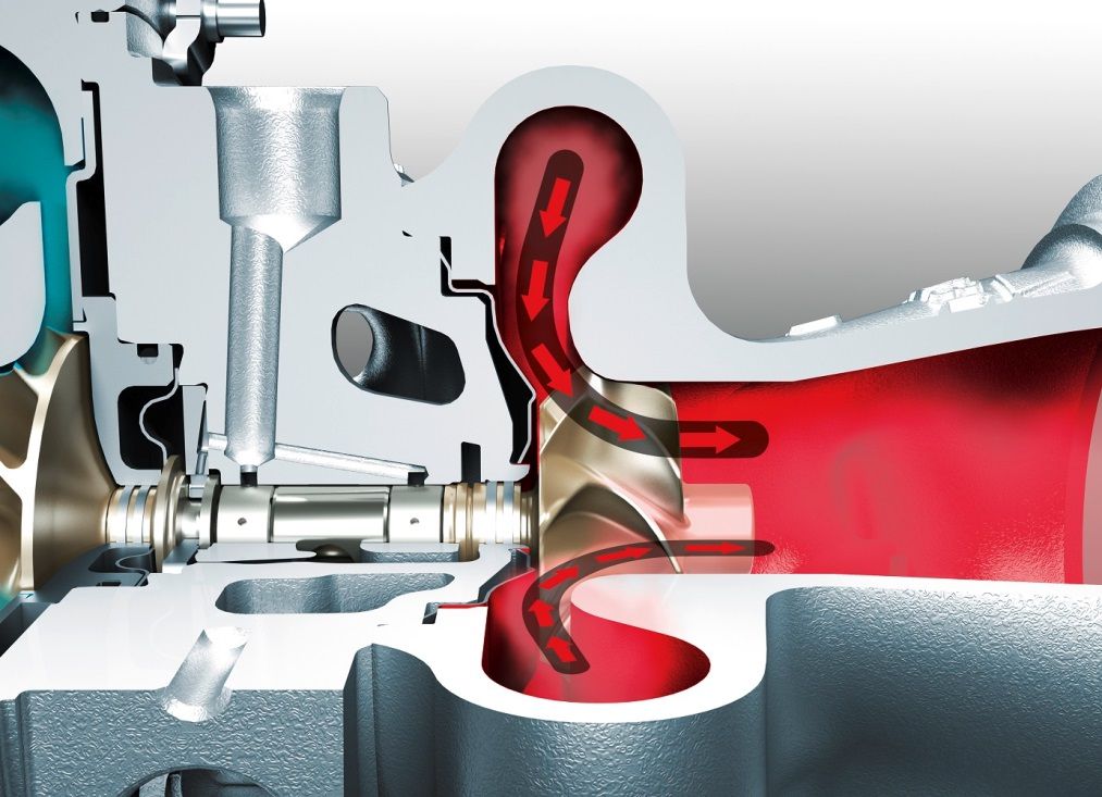
  • Regular maintenance of the shaft, such as lubrication and inspections, is necessary to prevent excessive wear or damage.

Importance of seals in preventing leaks and maintaining efficiency

Seals are critical components of the water pump assembly because they prevent leaks and maintain the pump’s efficiency. Here’s why seals are important:

  • Seals ensure that fluid (in this case, water) remains contained within the pump and doesn’t leak out.
  • They create a tight barrier between the rotating shaft and the pump casing, preventing any fluid from escaping.
  • By preventing leaks, seals help maintain the pump’s efficiency and prevent damage to other components due to fluid loss.
  • Mechanical seals are commonly used in water pumps and require regular inspections and maintenance to ensure proper functioning.
  • If a seal shows signs of wear or leakage, it should be replaced promptly to prevent further damage to the pump and maintain optimal performance.

Proper maintenance of the shaft and seals is crucial to ensure the longevity and efficiency of EMD water pumps. Regular inspections, lubrication, and replacement of worn or damaged parts are essential to prevent costly repairs and downtime. By understanding the role and importance of these components, you can take the necessary steps to maintain your water pump’s functionality.

IV. Bearings

Purpose of bearings in EMD water pumps

Bearings play a crucial role in the functionality of EMD water pumps. These components are responsible for reducing friction and allowing the smooth rotation of various parts within the pump. The main purposes of bearings in EMD water pumps are:

  1. Support: Bearings provide support to the rotating shaft and other moving parts, ensuring their stability and alignment.
  2. Reduced Friction: The bearings act as a barrier between the rotating shaft and the stationary parts of the pump, reducing friction and minimizing wear and tear.
  3. Load Distribution: Bearings distribute the load evenly across the different parts of the pump, ensuring efficient and reliable operation.
  4. Noise Reduction: By maintaining proper alignment and reducing friction, bearings contribute to quieter pump operation.

Types of bearings commonly used and their maintenance requirements

There are different types of bearings commonly used in EMD water pumps, each with its own maintenance requirements. Here are a few examples:

1. Ball Bearings: These bearings make use of steel balls to reduce friction and provide smooth rotation. They require regular lubrication and periodic inspection to ensure proper functioning.

2. Roller Bearings: Roller bearings use cylindrical rolling elements to support and guide the rotating shaft. Regular lubrication is essential, and occasional bearing replacement may be necessary.

3. Thrust Bearings: Thrust bearings are designed to handle axial loads, preventing the shaft from moving forward or backward. These bearings require proper lubrication and occasional inspection to check for any signs of wear or damage.

Proper maintenance of bearings in EMD water pumps is vital to ensure their longevity and the reliable operation of the pump itself. Here are some general maintenance tips:

  • Regularly lubricate the bearings as per the manufacturer’s recommendations.
  • Monitor the temperature of the bearings to detect any signs of overheating.
  • Keep the bearings clean and free from dust, debris, and contaminants.
  • Inspect the bearings periodically for any signs of wear, damage, or vibration.

By following these maintenance practices, you can ensure the optimal performance and longevity of the bearings in your EMD water pump, contributing to the overall efficiency and reliability of the system.

V. Housing and Cover

Functions of the housing and cover in the water pump assembly

The housing and cover are essential components of the EMD water pump assembly and play crucial roles in its functionality. Here are the main functions of these components:

1. Enclosing the impeller: The housing and cover enclose the impeller, which is responsible for creating the necessary pressure to pump water through the system. They ensure that the impeller operates in a controlled environment and prevents water leakage.

2. Creating a sealed chamber: The housing and cover create a sealed chamber around the impeller, ensuring efficient water flow and preventing air or fluid leaks. This sealing is necessary to maintain the desired pressure and prevent any external contamination.

3. Mounting the water pump: The housing and cover provide a stable and secure mounting for the water pump assembly. They ensure proper alignment with the engine and other components, minimizing vibrations and maintaining optimal performance.

Materials used and considerations for maintenance

The housing and cover are typically made of durable materials that can withstand the demanding conditions of the engine compartment. Common materials used include:

1. Cast iron: Cast iron is a popular choice for its strength and heat resistance. It provides excellent durability and corrosion resistance, making it suitable for long-term use in the water pump assembly.

2. Aluminum alloy: Aluminum alloy is another commonly used material due to its lightweight properties. It offers good heat dissipation and corrosion resistance, making it a practical choice for high-performance applications.

To ensure proper functionality and longevity of the housing and cover, regular maintenance is essential. Here are some considerations for maintenance:

1. Regular inspection: Perform visual inspections of the housing and cover for any signs of damage, such as cracks or corrosion. Timely identification of issues can help prevent further damage and ensure proper function.

2. Proper cleaning: Keep the housing and cover clean from dirt, debris, and coolant residue. Use a mild detergent and a soft brush or cloth to clean the surfaces. Avoid using harsh chemicals that can corrode the material.

3. Monitor coolant levels: Check the coolant levels regularly and ensure they are within the recommended range. Low coolant levels can lead to overheating, which can damage the water pump housing and cover.

By understanding the functions of the housing and cover in the water pump assembly and implementing proper maintenance practices, you can ensure the optimal performance and longevity of your EMD water pump.

VI. Maintenance Tips for EMD Water Pump Parts

To ensure optimal performance and longevity of your EMD water pump parts, it is essential to follow proper maintenance procedures. Here are some tips to keep your water pump running smoothly:

Regular inspection and cleaning procedures

• Check for leaks: Inspect the water pump system regularly for any signs of leaks. This includes checking the hoses, fittings, and seals for any cracks or damages that may cause leaks.

• Clean the pump intake: The pump intake can accumulate debris, such as dirt or leaves, which can hinder the flow of water. Regularly clean the intake area to prevent clogs and ensure proper water circulation.

• Monitor the water levels: Ensure that the water levels in the pump are at the recommended level. Insufficient water levels can lead to overheating and damage to the pump.

• Lubricate moving parts: Apply lubricant to the moving parts of the water pump, such as the bearings and impeller shaft, according to the manufacturer’s guidelines. This helps reduce friction and maintain smooth operation.

Replacement guidelines for worn or damaged parts

• Replace worn or damaged seals: Seals play a crucial role in preventing water leaks in the pump. If you notice any signs of wear or damage, replace the seals promptly to maintain the efficiency of the water pump.

• Replace worn or damaged impellers: The impeller is responsible for creating the water flow within the pump. If the impeller becomes worn or damaged, it may not efficiently move water through the system. Replace the impeller as needed to maintain optimal performance.

• Inspect and replace worn or damaged hoses: Hoses can deteriorate over time due to exposure to heat and chemicals. Regularly inspect the hoses for any signs of wear, such as cracks or bulges. Replace worn or damaged hoses to prevent leaks and ensure proper water flow.

With proper maintenance and timely replacements of worn or damaged parts, your EMD water pump will continue to function effectively and provide reliable water circulation. Remember, regular inspection and cleaning are key to preventing major issues and extending the lifespan of your water pump.

VII. Troubleshooting Common Issues

Common problems with water pump parts and their causes

Water pump parts can sometimes experience issues that affect their functionality. Here are some common problems and their possible causes:

1. Insufficient flow: If you notice a decrease in water flow, it could indicate a problem with the impeller, which may be worn out or damaged.

2. Leakage: Leakage can occur due to a faulty seal or gasket. Over time, these components can deteriorate and cause water to leak from the pump.

3. Overheating: Overheating is often caused by a malfunctioning thermostat or a clogged radiator. If the water pump is not circulating coolant properly, it can lead to engine overheating.

4. Noisy operation: Unusual noises, such as squeaking or grinding, can be a sign of a worn-out bearing or a misaligned pulley.

Steps to diagnose and resolve issues

If you encounter any of the above issues with your water pump parts, here are some steps you can take to diagnose and resolve the problems:

1. Conduct a visual inspection: Start by visually inspecting the water pump and its components for any signs of damage, such as cracks or leaks. Pay attention to the impeller, seals, and gaskets.

2. Check for proper coolant flow: Ensure that the coolant is flowing freely through the pump. If there is insufficient flow, it may be necessary to clean or replace the impeller.

3. Inspect for leaks: Check for any signs of leakage around the water pump. If you find a leak, replace the faulty seal or gasket.

4. Test the thermostat: To determine if the thermostat is functioning correctly, you can perform a simple test using a thermometer and a pot of boiling water. Follow the manufacturer’s instructions for thermostat testing.

5. Address noise issues: If you hear unusual noises coming from the water pump, it is essential to locate the source. Check the bearing and pulley for any damage or misalignment. Replace any worn-out components if necessary.

Remember, if you are unsure or uncomfortable with performing troubleshooting and repairs on your water pump, it is always recommended to seek assistance from a professional mechanic or technician.

VIII. Importance of Genuine EMD Water Pump Parts

Using genuine EMD water pump parts is crucial for the optimal performance and longevity of your EMD water pump. Here are some of the key reasons why using genuine parts is important:

Benefits of using genuine EMD parts

1. Reliable Performance: Genuine EMD water pump parts are specifically designed and manufactured to meet the high standards and specifications set by EMD. This ensures that the parts will fit seamlessly into your water pump and provide reliable performance.

2. Durability: Genuine EMD parts are made from high-quality materials and undergo rigorous testing to ensure their durability. They are built to withstand the demanding conditions of the marine industry and provide long-lasting performance.

3. Optimal Functionality: Genuine EMD parts are engineered to work harmoniously with other components of the water pump, ensuring optimal functionality. Using genuine parts will help maintain the efficiency and effectiveness of your water pump.

4. Warranty Coverage: When you use genuine EMD parts, you can take advantage of the warranty coverage provided by EMD. This gives you peace of mind knowing that your investment is protected and any potential issues will be addressed.

Risks of using counterfeit or aftermarket parts

Using counterfeit or aftermarket parts for your EMD water pump can lead to numerous problems and risks, including:

1. Compromised Performance: Counterfeit or aftermarket parts may not meet the same quality standards as genuine EMD parts. This can result in compromised performance and reduced efficiency of your water pump.

2. Increased Maintenance Costs: Using inferior parts may lead to more frequent breakdowns and failures, resulting in increased maintenance and repair costs over time. Genuine EMD parts help minimize the risk of unexpected repairs and costly downtime.

3. Safety Concerns: Counterfeit or aftermarket parts may not undergo the same rigorous testing and quality control processes as genuine EMD parts. This can pose safety risks for your equipment and potentially endanger the crew and vessel.

4. Voided Warranty: If you use non-genuine parts in your EMD water pump, it can void any existing warranty coverage. This means you will be responsible for any repairs or replacements needed, resulting in additional expenses.

It’s important to prioritize the use of genuine EMD water pump parts to ensure the optimal performance, durability, and safety of your equipment. By using genuine parts, you are investing in the long-term reliability and efficiency of your EMD water pump.

IX. Conclusion

In conclusion, understanding the functionality and importance of EMD water pump parts is crucial for maintaining the performance and longevity of your EMD locomotive. Here is a summary of the key points discussed in this guide:

  • EMD water pump parts play a vital role in the cooling system of EMD locomotives, ensuring that the engine operates within the optimal temperature range.
  • The main components of an EMD water pump include the impeller, volute, seals, bearings, and shaft, all of which work together to circulate coolant and remove heat from the engine.
  • Proper maintenance of EMD water pump parts is necessary to prevent overheating, engine damage, and costly repairs. Regular inspection, cleaning, and replacement of worn or damaged parts are essential for optimal performance.
  • Choosing quality water pump parts from reputable manufacturers is crucial to ensure reliability, durability, and compatibility with your EMD locomotive. Low-quality or incompatible parts can lead to reduced performance and premature failure.
  • It is important to follow the manufacturer’s guidelines and recommendations for maintenance and replacement intervals to keep your EMD locomotive operating smoothly.
  • Regularly monitoring coolant levels, temperature, and any signs of leaks or abnormal operating conditions can help detect potential issues with the water pump system early.
  • Ongoing training and knowledge about the functionality and maintenance of EMD water pump parts are essential for locomotive engineers and maintenance personnel.

Remember, investing in proper maintenance and choosing quality EMD water pump parts will result in long-lasting performance and minimize the risk of unexpected breakdowns or costly repairs.

For more information about EMD locomotives and water pump systems, you can visit the EMD locomotives Wikipedia page.

The Power Behind Locomotives: Exploring Electrical Parts and Their Role

The Power Behind Locomotives: Exploring Electrical Parts and Their Role

The power behind locomotives has been revolutionized by electrical components, enhancing their capacity, control, and efficiency. These locomotive parts and components form an intricate system that is responsible for locomotive operations. The traction motors convert electrical energy into mechanical energy, while the control systems manage the speed and functions of the locomotive. Transformers regulate the voltage and power distribution, while batteries provide backup power and support auxiliary systems. Wiring and connectors establish a reliable electrical connection, and protective devices are implemented to ensure system integrity. All of these locomotive contactors & electrical parts, such as the locomotive contactor and line contactor in locomotive contribute to the overall power and operations of the locomotive, making it vital to understand the role and significance of these locomotive parts name.

Introduction to Locomotive Electrical Systems

Understanding the fundamentals of locomotive electrical systems is essential for any railway technician. Electricity is an integral part of modern locomotives, providing power to many vital systems. To understand how electricity is used in locomotives, it is important to learn about the overview of locomotive electrical systems, the role of electrical parts, and the components of a typical locomotive electrical system.

Overview of Locomotive Electrical Systems

Building on the previous section, the subsequent section will provide an overview of locomotive electrical systems. From the basic components of a locomotive electrical system to the role of electrical parts, understanding how locomotives operate is essential in maintaining the safety and efficiency of operations.

The locomotive electrical system is a complex network of electrical parts that power and control the various systems of a locomotive. These components enable the locomotive to draw power from the main power source or from an auxiliary power source. It also helps the locomotive to move along the track and adjust the speed according to the conditions.

The primary components of the locomotive electrical system include generators, motors, control systems, regulators, inverters, and transformers. Generators are responsible for generating and supplying the power to the locomotive while motors convert electrical energy into mechanical energy to propel the locomotive. Control systems provide the necessary instructions to the locomotive to control the speed, direction, and brake system. Regulators are responsible for controlling the voltage and current level of the electrical system while inverters convert alternating current (AC) to direct current (DC). Transformers are used to step-up or step-down the voltage in the locomotive’s electrical system.

The locomotive electrical system is essential in ensuring a safe and efficient operation of the locomotive. By understanding the components and operation of the system, maintenance personnel can identify potential issues and take the necessary steps to ensure the safe and efficient operation of the locomotive.

The Role of Electrical Parts in Locomotives

Now that an overview of locomotive electrical systems has been presented, it is important to understand the role of electrical parts in locomotives. Electrical parts can be thought of as the foundation of a locomotive, as they provide the power and control necessary for the smooth operation of the vehicle. They are responsible for controlling the speed, direction, lighting, and other functions. Electric parts also play an important role in safety, as they ensure that the locomotive is operating in a safe and reliable manner.

To understand the role of electrical parts in locomotives, it is important to understand the different types of components that make up a typical locomotive electrical system. These components include: motors, generators, rectifiers, controllers, transformers, and wiring. Each of these components plays an important role in the operation of the locomotive, and understanding their roles is essential for proper maintenance and upkeep.

The motors are the primary source of power for the locomotive. They provide the force that moves the wheels and other parts of the locomotive. Generators are responsible for converting mechanical energy from the motors into electrical energy. Rectifiers are used to convert alternating current (AC) from the generator into direct current (DC) that is used to power the motors and other systems. Controllers are responsible for regulating the power output of the motors and other components. Transformers are used to step down electrical voltages to the correct levels for use in the locomotive. Finally, wiring is used to connect the various components of the locomotive together and provide a safe and reliable connection.

These components are essential for the safe and reliable operation of the locomotive. Without them, the locomotive would not be able to move or function properly. It is important to understand the roles of electrical parts in locomotives in order to maintain them properly and ensure that they are functioning correctly. This knowledge will help to ensure the safe and reliable operation of the locomotive.

Components of a Typical Locomotive Electrical System

The air crackles with anticipation as the engine comes to life, emitting a low hum that gradually increases in intensity. It is a marvel of engineering, and its success relies on the careful integration of components of the locomotive electrical system. This system allows the engine to convert electrical energy into mechanical energy to power the vehicle, and it is composed of several components.

Electric motors are the primary source of power for a locomotive. These motors are connected to the axle through a series of gears, allowing the engine to generate torque to move the vehicle. Electric motors require a certain amount of electrical current to operate, so the system must include devices to regulate the flow of electricity.

Generators produce the electricity that powers the motors. Generators are typically connected to the axle and spin as the locomotive moves, thus producing the necessary electricity. Generators must be connected to the engine to provide a steady flow of electricity, and the engine must be regulated to ensure that the generators produce the right amount of electricity.

Control systems are responsible for regulating the flow of electricity and the speed of the locomotive. Control systems are composed of several components, including relays, switches, and circuit breakers. The relays control the flow of electricity, while the switches and circuit breakers regulate the speed of the locomotive.

The components of the locomotive electrical system work together to provide the engine with the necessary power to move the vehicle. By regulating the flow of electricity and the speed of the locomotive, these components help ensure that the engine runs smoothly and efficiently.

Locomotive Batteries

The power of locomotives lies in their batteries. From Nickel Cadmium to Lithium-ion, a variety of battery types are used in locomotives to store and deliver energy. This energy can be used to power the locomotive for extended periods of time without needing to refuel. Furthermore, battery-powered locomotives are an eco-friendly alternative, providing a number of benefits to the environment.

Battery Types Used in Locomotives

Moving on from the electrical systems within locomotives, the topic of locomotive batteries is an essential component of a successful locomotive. There are various types of batteries used in locomotives, each providing unique benefits and drawbacks.

Lead-acid batteries are the most common type of battery used in locomotives. This type of battery has deep cycles and is able to hold a charge for longer periods of time, making them ideal for the onboard power supply of the locomotive. Lead-acid batteries are also capable of withstanding extreme temperatures, making them a reliable and cost-effective option.

Lithium-ion batteries are the newest type of battery used in locomotives, and they boast many advantages. They are lightweight, compact, and able to store more energy than lead-acid batteries, making them more suitable for powering the locomotive. Furthermore, lithium-ion batteries have a longer life cycle compared to lead-acid batteries, which helps to reduce maintenance costs.

Finally, nickel-cadmium batteries are also used in locomotives, though not as commonly as lead-acid or lithium-ion batteries. Nickel-cadmium batteries are able to produce higher voltages than lead-acid batteries and are ideal for applications that require high voltage power. However, they are more expensive than lead-acid and lithium-ion batteries, and require more maintenance due to their shorter life cycle.

In conclusion, the type of battery used in locomotives depends on the application and the desired outcome. Lead-acid batteries are the most common, but lithium-ion and nickel-cadmium batteries offer unique advantages that may be preferable for certain applications.

How Locomotive Batteries Store and Deliver Energy

The power of locomotives is generated from a combination of mechanical and electrical energy, and the power of locomotive batteries lies in their ability to store and deliver this energy. In order to better understand how locomotive batteries store and deliver energy, it is important to understand the different types of batteries used in locomotives.

The most common types of batteries used in locomotives are lithium-ion and lead-acid batteries. Lithium-ion batteries are lightweight and compact, making them an ideal choice for locomotive applications. They are capable of storing and delivering large amounts of energy and can last for up to 10 years. Lead-acid batteries, on the other hand, are heavier and more cumbersome than their lithium-ion counterparts. They are also more affordable and can store and deliver energy for longer periods of time.

Regardless of the type of battery used, how locomotive batteries store and deliver energy is the same. When the battery is charged, electrons are transferred from the battery to the locomotive’s electrical system. This electrical energy is then used to power the locomotive’s various components, such as the engine, lighting, and brakes. When the battery is discharged, the electrons are transferred back to the battery, storing the energy until it is needed again.

The use of locomotive batteries is advantageous for a variety of reasons. Battery-powered locomotives are able to move freely without the need for overhead power lines, allowing them to operate in areas where overhead power is unavailable or impossible. Additionally, batteries are able to provide a steady and reliable source of energy, eliminating the need for frequent stops and starts. Finally, battery-powered locomotives are more efficient and cost-effective than traditional diesel locomotives.

The power of locomotive batteries lies in their ability to store and deliver energy to the locomotive’s electrical system. By understanding how locomotive batteries store and deliver energy, we can better appreciate the advantages that battery-powered locomotives offer.

Benefits of Battery-Powered Locomotives

As railway technology continues to progress, the use of battery-powered locomotives is becoming increasingly popular. Battery-powered locomotives offer many benefits that make them an attractive option for operators. In this section, the focus will be on the benefits of battery-powered locomotives.

One of the primary advantages of battery-powered locomotives is their reduced emissions. Battery-powered locomotives do not produce any emissions while in operation, as they rely solely on electricity for power. This means that they can be operated without contributing to air pollution, allowing for a cleaner and healthier environment. Furthermore, battery-powered locomotives are often designed to be more energy efficient than traditional diesel-powered locomotives, which can lead to significant cost savings.

Battery-powered locomotives are also more reliable than their diesel-powered counterparts. This is because they do not require as much maintenance due to their reliance on electricity instead of diesel fuel. This means that they are less likely to experience breakdowns, which can lead to fewer delays and improved operational efficiency. Additionally, battery-powered locomotives are quieter than traditional diesel-powered locomotives, which can make them more suitable for use in urban areas.

Battery-powered locomotives also offer improved safety features. Many battery-powered locomotives are equipped with advanced safety systems that can detect potential hazards before they become a problem. This can help to prevent accidents and improve the overall safety of rail operations, which is beneficial for both operators and passengers.

Overall, battery-powered locomotives offer many advantages that make them an attractive option for operators. From reduced emissions and greater reliability to improved safety and cost savings, battery-powered locomotives provide numerous benefits that make them an ideal choice for railway operators.

Locomotive Generators

Locomotives require an immense amount of power to operate, which is why generators are essential components. There are several types of generators used in locomotives, each supplying its own set of advantages. Generators create power for locomotives through a variety of different ways, such as converting mechanical energy to electrical energy. The benefits of generator-powered locomotives are numerous, including increased efficiency and a reduced environmental impact.

Types of Generators Used in Locomotives

Moving on from batteries, generators are another important component of locomotives. Generators serve to create the power necessary for locomotives to run, and there are a few different types of generators used in locomotives.

The most common type of generator used in locomotives is the electric generator. This type of generator produces electricity by using magnets and by spinning a coil of wire inside the magnetic field. This spinning of the coil creates a flow of electrons, which then creates electricity. This electricity is then used to power the locomotive.

Another type of generator used in locomotives is an alternator. Alternators work similarly to electric generators, but they use a different type of magnet. Alternators also create a flow of electrons which produces electricity, but they are typically more efficient than electric generators.

The last type of generator used in locomotives is a micro-hydro generator. This type of generator uses water pressure to create electricity. These generators are typically used in remote areas, and they are a relatively new technology. Micro-hydro generators can be used to power both locomotives and other machines.

Generators are an essential component of locomotives, and there are a few different types of generators used in locomotives. Electric generators, alternators, and micro-hydro generators are all used to create the power necessary for locomotives to run.

How Generators Create Power for Locomotives

Making the transition from batteries to generators, it’s important to understand how generators are able to create power for locomotives. Generators, which are typically powered by diesel engines, are able to convert mechanical energy into electrical energy. This is done by using the magnetism of an armature in order to produce a current.

The generator consists of two main components: the stator and the rotor. The stator is stationary and consists of a series of windings of copper wire that are wound around a metal frame. These windings create a magnetic field. Meanwhile, the rotor is a collection of magnets that turn within the stator. When the rotor turns, it creates a rotating magnetic field that induces a current in the stator. This current then passes through a set of wires to the load, which is the locomotive.

The process of converting mechanical energy into electrical energy requires the use of a voltage regulator. This device regulates the output voltage of the generator by controlling the rotor speed. In order to maintain a steady output voltage, the regulator will adjust the rotor speed when the load on the locomotive changes. This ensures that the electrical power supplied to the locomotive remains consistent and reliable.

The generator-powered locomotive has several advantages over a locomotive powered by batteries. Generators are able to provide a more consistent and reliable power source, allowing for smoother operation of the locomotive. Generators are also more efficient, meaning they require less energy to produce the same amount of power. Finally, generators are able to provide a larger power output than batteries, meaning they can power larger locomotives.

Benefits of Generator-Powered Locomotives

Having discussed the different types of generators used in locomotives, as well as how these generators create power, it is important to then consider the advantages of utilizing generators as the primary power source for these powerful machines.

The primary benefit of generator-powered locomotives is the increased efficiency and decreased environmental impact when compared to traditional methods. Electricity generation is more efficient than burning fuel, meaning that generator-powered locomotives can travel farther on the same amount of fuel. This efficiency also translates into lower emissions of pollutants, such as carbon dioxide, sulfur dioxide, and nitrogen dioxide, making it a healthier choice for the environment.

Another benefit of generator-powered locomotives is the improved safety it provides. Since electricity is the primary power source, it eliminates the risk of fuel explosions or fires, which can be catastrophic if they occur. Additionally, since there is no need for frequent refueling, it reduces the amount of time the locomotive is idle and therefore reduces the risk of accidents.

Finally, generator-powered locomotives provide increased reliability and convenience. Electric motors require less maintenance than internal combustion engines and therefore have fewer breakdowns. Additionally, the ease of refueling with electricity means that locomotives can travel longer distances without needing to stop for fuel. This can save time and money for the railroad company, as well as providing a more reliable service to passengers.

In conclusion, generator-powered locomotives provide a number of advantages over traditional methods, including increased efficiency and environmental friendliness, improved safety, and increased reliability and convenience. These benefits make it an attractive option for those looking to modernize their locomotive fleet.

Locomotive Motors

The locomotive motor is a complex machine composed of a variety of components. Types of motors used in locomotives can range from simple DC motors to complex AC induction motors. These motors allow locomotives to convert electrical energy into mechanical work, powering the wheels of the train and providing the necessary thrust and torque to move the vehicle. The benefits of motor-powered locomotives include improved fuel efficiency, reduced maintenance costs, and increased safety.

Types of Motors Used in Locomotives

The generators discussed in the previous section transform mechanical energy into electrical energy, but what happens when electrical energy needs to be transformed into mechanical energy? This is where locomotive motors come in. Types of Motors Used in Locomotives are a critical component of the locomotive’s power system.

The most common type of motors used in locomotives are DC Motors. A DC Motor is an electromagnetic device that converts electrical energy into mechanical work. It consists of two main components: a stator and a rotor. The stator is the stationary part of the motor and contains a set of windings that generate a magnetic field when energized. The rotor is the rotating part of the motor and contains a set of rotor conductors. When a voltage is applied to the stator, the magnetic field generated by the stator interacts with the rotor. This interaction causes the rotor to rotate, converting electrical energy into mechanical energy.

The second type of motor used in locomotives is the AC Motor. An AC Motor is a type of electric motor that operates on alternating current. It is similar to a DC Motor in that it consists of a stator and a rotor, with the stator generating the magnetic field that interacts with the rotor. However, the stator in an AC Motor is designed to generate an alternating magnetic field, which causes the rotor to rotate at a much higher speed than a DC Motor.

The third type of motor used in locomotives is the Synchonous Motor. A Synchonous Motor is a type of AC Motor that operates at a constant speed, regardless of the load. It consists of a stator and a rotor, with the stator generating a magnetic field that is synchronized with the rotor. As the rotor rotates, it generates an alternating current that is fed back to the stator, allowing the motor to maintain a constant speed.

By using these types of motors, locomotives are able to convert electrical energy into mechanical energy and propel the train forward. In addition to providing power to the locomotive, these motors also provide other benefits, such as increased efficiency, reduced maintenance costs, and improved reliability.

How Motors Convert Electrical Energy Into Mechanical Work

Having discussed the various types of generators used in locomotives, it is now time to explore how motors convert electrical energy into mechanical work. Motors are the opposite of generators. Where generators convert mechanical energy into electrical energy, motors convert electrical energy into mechanical energy. This conversion of energy is what powers the locomotive forward.

The most common type of motor used in locomotives is an asynchronous induction motor. This motor works by converting electrical energy into mechanical torque. This is done through the use of a rotating magnetic field created by the motor’s stator. This magnetic field interacts with the rotor, which is connected to the locomotive’s axles, to rotate it. As the rotor rotates, it powers the axles which move the locomotive forward.

Asynchronous induction motors are ideal for locomotives because they are capable of providing a high torque output at low speed. This makes them perfect for powering the large and heavy locomotives. Additionally, these motors can be easily controlled by varying the frequency of the current being supplied to them. This allows the motors to easily match the speed of the locomotive which further increases efficiency.

Finally, asynchronous induction motors are also relatively cheap and easy to maintain. This makes them a cost-effective option for powering locomotives. In sum, asynchronous induction motors are the motor of choice for powering locomotives due to their ability to provide a high torque output, ease of control, and low maintenance costs.

Benefits of Motor-Powered Locomotives

The advantages of locomotives powered by electrical motors are numerous. The most obvious is the high efficiency of the motors, which translates to increased fuel savings. By converting electrical energy into mechanical work, motors provide greater torque, allowing locomotives to pull heavier loads than those powered by steam. This increased power also results in improved acceleration, allowing locomotives to reach their destination faster. Additionally, the use of electrical motors requires less maintenance than traditional steam-powered engines, leading to fewer delays and improved reliability.

The elimination of steam and exhaust emissions is another important benefit of using motors to power locomotives. By running on electricity, locomotives do not produce any pollutants, reducing their environmental impact. This makes them much more sustainable than traditional steam-powered engines, which can cause air pollution and contribute to global warming. Furthermore, electric motors are quieter than traditional steam engines, creating a more pleasant environment for passengers and those living near railway tracks.

The use of electrical motors also offers improved safety. Since motors do not require open flames or hot surfaces, they reduce the risk of fire and explosions. Additionally, due to their high efficiency, electric motors can be run at lower speeds, minimizing the risk of derailment. Furthermore, electric motors are much lighter than steam-powered engines, reducing the wear and tear on the tracks and decreasing the likelihood of accidents.

Finally, electric motors provide greater flexibility for locomotive design. They can be easily incorporated into existing locomotives, allowing them to be adapted to different terrain and conditions. Furthermore, they can be used in combination with other power sources, such as batteries or regenerative braking, allowing for greater control and efficiency. With their numerous advantages, it is clear that electric motors are the way of the future for locomotives.

Locomotive Traction Control Systems

The locomotive traction control system is an important component of modern railway operations, providing greater control to the locomotive and improved efficiency of rail operations. It is a complex system which involves a variety of control systems, sensors, and other components. To understand how locomotive traction control systems work and the associated benefits, let’s first take an overview of the system and then explore how they help locomotives and the associated benefits.

Overview of Traction Control Systems

The roar of the locomotive engine is a powerful reminder of the past, but the future of locomotive technology requires the implementation of sophisticated traction control systems. By taking into account the physics of locomotive motion, traction control systems provide unprecedented control of locomotive performance. In this section, we will provide an overview of traction control systems and their role in the locomotive industry.

The first step in understanding traction control systems is to recognize the complexities of locomotion. From the immense amount of energy required to move the train to the force of the track, locomotives must be able to receive and respond to a variety of environmental inputs. Traction control systems take into account these inputs and provide a comprehensive control system that can optimize locomotive performance.

At the core of traction control systems is the use of both mechanical and electrical components. Mechanical components are used to detect changes in the speed of the locomotive, while electrical components monitor the power output of the engine. By combining these two systems, traction control systems can provide a wide range of control options, from speed control to torque control.

Traction control systems also provide additional benefits to locomotive operators. By using an adaptive control system, the traction control system can automatically respond to changes in environment and optimize the performance of the locomotive. This allows locomotives to handle a variety of scenarios with greater control and efficiency. Furthermore, traction control systems are designed to be highly reliable, reducing the risk of breakdowns and delays due to mechanical failure.

In summary, traction control systems provide a comprehensive control system for locomotive operators. By combining mechanical and electrical components, traction control systems can provide precise control of locomotive performance. Additionally, traction control systems provide an adaptive response that allows for increased efficiency and reliability. As the locomotive industry moves into the future, traction control systems will continue to be an integral part of locomotive technology.

How Traction Control Systems Help Locomotives

The power of locomotive motors is undeniable, but it’s only as effective as the system that controls it. Traction control systems provide the necessary regulation to ensure that locomotives can reach their full potential.

Traction control systems are designed to optimize locomotive performance and efficiency. These systems allow locomotives to draw the maximum amount of power from their motors, while operating safely and reliably. The system works by monitoring and adjusting the amount of force applied to the rail, and by controlling the speed and acceleration of the locomotive.

This system helps ensure that the locomotive is able to reach its desired speed without experiencing any slip or skid. Traction control systems can also detect when there is a change in the rail’s surface, and it can adjust the force applied accordingly. This ensures that the locomotive can maintain its desired speed and acceleration, and that it does not experience any unexpected jerks or sudden stops.

The system can also detect when a locomotive is running on a track with limited or uneven traction. In these cases, the traction control system can adjust the speed and force applied to the rail to ensure that the locomotive maintains its desired speed and acceleration. This ensures that the locomotive can operate safely and reliably.

Traction control systems are essential for ensuring that locomotives can reach their full potential and operate safely and reliably. By monitoring and adjusting the force applied to the rail, these systems ensure that locomotives can safely reach their desired speed and acceleration, no matter what the track conditions may be.

Benefits of Traction Control Systems

Switching gears, let us explore the benefits of traction control systems for locomotives. Traction control systems are essential for locomotives to optimize their performance and increase their efficiency of energy utilization. With the use of traction control systems, locomotives are able to benefit from improved acceleration, smoother deceleration, and better adhesion to the track.

These systems are also designed to reduce the amount of wear and tear on the locomotives, as they use less energy to maintain the same speed as before. By reducing the amount of energy required to keep the locomotive moving, the engine can be better cooled and maintained, leading to improved performance and less frequent need for repairs. Additionally, these systems are designed to help reduce the emissions of the locomotives, making them run cleaner and more efficiently.

The most important benefit of traction control systems is the improved safety that they provide. By improving the locomotive’s ability to brake and accelerate, the risk of an accident is greatly reduced, as an unexpected stop or movement of a train can be quickly corrected with the help of these systems. The ability to keep the locomotives in control even in difficult conditions, such as those caused by snow, ice, or rain, is also a great advantage of the traction control systems.

Ultimately, traction control systems are essential for locomotives to optimize their performance and increase their efficiency of energy utilization. With the use of these systems, locomotives are able to benefit from improved acceleration, smoother deceleration, reduced wear and tear, cleaner emissions, and improved safety.

Locomotive Electrical Circuitry

The modern locomotive is a complex system of electrical circuitry, designed to power and improve its performance. This overview will explore the electrical components and their benefits in locomotive design. In particular, we’ll examine how electrical circuits can improve locomotive performance, and the benefits of electrical circuitry in locomotives.

Overview of Locomotive Electrical Circuits

Building on the advancements of locomotive traction control systems, locomotive electrical circuitry is a further refinement that can significantly improve the performance of locomotives. An overview of locomotive electrical circuits reveals the ways that these circuits can improve the operation of locomotives and the benefits they bring.

The basic components of locomotive electrical circuits include the motor control circuits, the power supply circuits, the communication circuits, and the load circuits. These components interact with each other to allow the locomotive to function properly. The motor control circuits control the speed and direction of the locomotive, the power supply circuits provide the power for the locomotive, the communication circuits provide a means of communication between the locomotive and the control systems, and the load circuits regulate the load on the locomotive. All these components work together to ensure the locomotive is functioning properly.

The primary purpose of the locomotive electrical circuits is to provide the necessary power to the locomotive and to ensure that the locomotive is operating safely. The power supply circuits provide the power to the locomotive and the motor control circuits control the speed and direction of the locomotive. The communication circuits provide communication between the locomotive and the control systems, and the load circuits regulate the load on the locomotive. All these components work together to ensure the locomotive is operating safely and efficiently.

The most important components of locomotive electrical circuits are the power supply circuits and the motor control circuits. The power supply circuits provide the power to the locomotive and the motor control circuits control the speed and direction of the locomotive. Without these components, the locomotive would not be able to move. The communication circuits and the load circuits are also important components of locomotive electrical circuits. They provide a means of communication between the locomotive and the control systems and regulate the load on the locomotive, respectively. All these components work together to ensure the locomotive is operating safely and efficiently.

How Electrical Circuits Can Improve Locomotive Performance

Having explored the fundamentals of locomotive traction control systems, it is now time to delve into the world of locomotive electrical circuitry. Electrical circuitry in locomotives can be incredibly complex, but it provides an array of benefits when it comes to improving locomotive performance.

The primary way in which electrical circuitry can enhance locomotive performance is by providing a reliable source of power. Modern locomotives are powered by a combination of electricity and diesel. The locomotive’s electrical system provides the power that is needed to start the engine, operate the brakes, and power the lights and other equipment. By providing a reliable source of power, the locomotive’s performance is improved.

Another way in which electrical circuitry can improve locomotive performance is by increasing efficiency. Modern locomotives are equipped with electrical systems that are designed to be more efficient than their predecessors. By utilizing electricity more efficiently, the locomotive is able to reduce fuel consumption and emissions. This results in a more efficient locomotive that is better for the environment.

Finally, electrical circuitry can also improve locomotive performance by providing improved safety features. Electrical systems in modern locomotives are designed to be more reliable and offer additional safety features. This includes features such as advanced brake systems, automated speed control, and improved lighting. All of these features help to make locomotives safer and more reliable.

In conclusion, electrical circuitry is essential to improving locomotive performance. By providing a reliable source of power, increasing efficiency, and offering improved safety features, electrical circuitry can greatly enhance locomotive performance.

Benefits of Electrical Circuitry in Locomotives

The benefits of incorporating electrical circuitry in locomotives cannot be understated. Electrical circuitry provides superior control and power distribution, which can greatly enhance the performance of the locomotive. There are many advantages to using electrical circuitry in locomotives, including improved safety, increased efficiency, and enhanced reliability.

One of the most significant benefits of electrical circuitry in locomotives is improved safety. Incorporating electrical circuitry into locomotives allows for increased monitoring of multiple systems, which helps to ensure that all components are operating correctly. Sensors can detect issues with the various systems, alerting the operator to any potential problems. This can help prevent accidents and malfunctions, resulting in improved safety for both the locomotive and its passengers.

Another advantage of electrical circuitry in locomotives is increased efficiency. By utilizing electrical circuitry, the locomotive can be operated at optimal performance levels, reducing the amount of wasted energy. This can result in more efficient operation, resulting in reduced fuel consumption and emissions. Additionally, electrical circuitry can help reduce the amount of maintenance required, as components can be monitored remotely and replaced before they become a problem.

Finally, incorporating electrical circuitry into locomotives can provide enhanced reliability. With the use of advanced monitoring systems, components can be quickly identified and replaced when needed. This can help prevent downtime and ensure that the locomotive is operating at its peak performance. Additionally, electrical circuitry can help reduce the number of potential breakdowns, making the locomotive more reliable for long-term use.

In conclusion, the benefits of incorporating electrical circuitry into locomotives are undeniable. This technology provides improved safety, increased efficiency, and enhanced reliability, making it an invaluable asset for any locomotive operator. By utilizing this technology, locomotives can operate at their peak performance, helping to reduce fuel consumption and emissions, and ensuring the safety of its passengers.

Locomotive Signal Systems

Understanding how locomotive signal systems work is essential for controlling and optimizing locomotive movements. These systems provide a combination of visibility, communication, and control capabilities that ensure safe and efficient operations. To gain a better understanding of locomotive signal systems, let’s take a look at an overview, how they help control locomotive movements, and the benefits they provide.

Overview of Locomotive Signal Systems

Having now discussed the intricacies of locomotive electrical circuitry, it is time to move onto the realm of locomotive signal systems. Signal systems are vital components of any functioning railway, as they provide the framework for the safe and efficient control of locomotive movements. An overview of locomotive signal systems is presented here to provide an understanding of the key components that make up these systems and how they help control locomotive movements.

At the core of any locomotive signal system is the signal. This is an indication of the permission for a train to proceed, and generally consists of a combination of light signals, horns and flags. Depending on the type of signal, these can indicate the direction a train should take or the speed that should be maintained. The signals are placed along the track, and will usually be placed no more than a few hundred metres apart.

In addition to signals, there are various other components of a signal system, such as track circuits and interlockings. Track circuits are used to detect when a train is passing, and are used to provide a safe distance between two trains. Interlockings are used to ensure that a signal cannot be changed until the route ahead is clear, and are often used at railway junctions to prevent collisions.

Signal systems also rely on signal boxes, which are used to operate and control the signals and other components. Signal boxes are unmanned and will contain a number of levers and buttons that are used to control the signals. Signal boxes also have monitors that allow engineers to monitor the tracks and ensure that the signals are working correctly.

The combination of signals, track circuits, interlockings and signal boxes makes up the core components of a locomotive signal system. By understanding how these components work together, we can begin to understand how signal systems help to control locomotive movements.

How Signal Systems Help Control Locomotive Movements

_Moving forward, locomotive signal systems provide the necessary guidance and control for locomotives to traverse the rails safely. These systems are designed to detect the presence of a train in the area and to ensure that the train remains in a safe operating condition._

_Signal systems are a crucial part of the overall locomotive control system. They are used to inform the engineer of the train’s operating condition, such as speed, direction, and braking. They also indicate when it is safe for the train to proceed, as well as when the engineer must reduce the speed or stop the train._

_The signal systems help the engineer to control the locomotive by providing visual and audio warnings. For example, a red signal may indicate that the train should stop, while a green signal may indicate that the train can proceed. Additionally, an audible warning may be issued if a train is approaching a section of track that is blocked or if the speed needs to be reduced._

_The signal systems also provide information to the engineer on the current track layout. This includes information on track switches, crossovers, and other track features that the engineer needs to be aware of to safely operate the train._

Benefits of Locomotive Signal Systems

Having discussed the overview of locomotive signal systems and how they help control locomotive movements, a key advantage of having such a system in place is that it facilitates safer and more efficient train operations. With the help of these systems, the risk of collisions between trains is substantially reduced, as the signals provide the necessary guidance for locomotives to operate in a coordinated manner. Additionally, the signals provide a safe and secure means of communication between the control center and the train operators.

The robustness of locomotive signal systems is one of the major benefits that it offers. The systems are designed to withstand the extreme weather conditions that are common in many parts of the world. Furthermore, the systems are equipped with fail-safe mechanisms that can detect any potential problems and alert the appropriate personnel of the situation. This ensures that the signal systems are constantly operating at peak efficiency with minimal chances of any breakdowns.

Another benefit of locomotive signal systems is that they provide greater flexibility when it comes to the route that the train is supposed to take. The signals provide the necessary guidance for the train to take the most efficient route, while also ensuring that the train stays within the confines of the designated tracks. This helps to maximize the efficiency of the operation and minimize the amount of time required for the train to reach its destination.

Finally, the automation of locomotive signal systems provides a greater level of accuracy and reliability to the operation. The signal systems are designed to be able to detect any potential problems and alert the appropriate personnel of the situation. Furthermore, the automation of these systems ensures that the train is always running on the designated tracks, thus providing a much safer operation.

Locomotive Electronics

From small sensors to sophisticated microprocessors, locomotive electronics are essential to ensuring a safe and efficient journey. Such electronics provide the ability to control locomotive performance, enabling engineers to monitor and adjust systems like fuel consumption, braking, and speed. Furthermore, electronics are used to maintain a high level of safety, allowing operators to quickly and easily identify mechanical issues.

Types of Electronics Used in Locomotives

As railroads continue to modernize, the need for sophisticated electronics in locomotives is growing. Train engineers now have the ability to monitor and control the performance of their locomotives with the help of a variety of electronics. In this section, we will explore the different types of electronics used in locomotives, how they help to control locomotive performance, and the benefits of using these electronics.

At the heart of locomotive electronics are the microprocessors. These computers, often called ECUs (electronic control units), are responsible for running the locomotives’ control systems and are used to manage the engine, brakes, and other locomotive components. The microprocessors collect data from the various sensors located throughout the locomotive and use this data to make decisions about how the locomotive should be operated.

Communication systems are also used in locomotives to enable the engineer to communicate with other locomotives and with the dispatchers. These systems allow the engineer to send and receive messages, and to coordinate their movements with other locomotives in the area. Communication systems are also used to monitor the status of the locomotive and to alert the engineer when something is not working as it should.

Finally, navigation systems are used to help the engineer find the right route and to keep the locomotive on track. Navigation systems use GPS and other sensors to provide the engineer with information about the terrain, obstacles, and other potential dangers. Navigation systems can even provide information on the speed, direction, and location of the locomotive, allowing the engineer to make adjustments to ensure the locomotive is running safely and efficiently.

These are just a few of the types of electronics used in locomotives to help control locomotive performance. By utilizing these electronics, locomotive engineers can ensure that their locomotives are running safely and at peak performance, resulting in improved operational efficiency and overall performance.

How Electronics Help Control Locomotive Performance

Having discussed the various types of electronics used in locomotives, it is now worthwhile to explore how these electronics help control locomotive performance. Electronic systems have become increasingly important in the operation of modern locomotives, and they can be used to monitor and maintain the performance of a locomotive in a variety of ways.

From a safety perspective, sophisticated electronic systems can be used to detect irregularities in the operation of a locomotive, such as overheating, overspeed, or other issues. This allows operators to take corrective action before a more serious problem develops. Additionally, electronic systems can be used to perform routine checks on the locomotive, such as monitoring the performance of its brakes and traction systems.

From a maintenance perspective, electronic systems can be used to monitor the performance of a locomotive over time. As the locomotive operates, sensors can collect and store information about its performance, which can then be used to diagnose and troubleshoot any problems that may arise. Additionally, electronic systems can be used to schedule and track maintenance, ensuring that the locomotive is always running at its optimal performance.

Finally, electronic systems can also be used for optimization purposes. By collecting data on the performance of the locomotive over time, operators can identify areas where improvements can be made to its operation. This can involve both minor adjustments, such as adjusting engine timing to improve fuel efficiency, or more major changes, such as upgrading components of the locomotive to increase its performance. In any case, electronic systems provide an invaluable tool for monitoring and optimizing the performance of a locomotive.

Benefits of Locomotive Electronics

The introduction of electronics to locomotives has revolutionized the way they are operated and maintained. Beyond the new capabilities offered by these modern technologies, locomotives are now safer and more efficient than ever before. Moving away from the traditional mechanical systems of the past, the benefits of locomotive electronics are numerous.

One of the primary advantages of using electronics in locomotives is its ability to monitor and analyze performance metrics. Using sensors and data logging systems, information about the locomotive’s operation is collected and analyzed, allowing operators to make informed decisions about its performance. This can help identify potential problems before they become serious, saving time and money in the long run.

Another benefit of locomotive electronics is the improved safety they provide. By monitoring engine speed, temperature, and other factors, risks are minimized, increasing the safety of the operation. Additionally, by providing better control of the locomotive, the chances of derailment and other accidents are reduced.

Finally, the use of electronics in locomotives has improved their operational efficiency. By monitoring performance, operators can identify areas of improvement and increase fuel efficiency. This can lead to significant cost savings, as well as reduced emissions.

In short, the use of electronics in locomotives provides a number of valuable benefits. From improved safety and efficiency, to better performance monitoring and analysis, the advantages of locomotive electronics are clear. By taking advantage of these modern technologies, operators can ensure their locomotives are performing at their best.

Locomotive Monitoring Systems

The overview of locomotive monitoring systems focuses on understanding the components of the system and how they work together to improve locomotive performance. The system’s components can be used to diagnose faults and provide real-time updates on the locomotive’s condition. In addition, how monitoring systems help improve locomotive performance is explored by examining the ways the systems can monitor and analyze machine data, detect faults, and optimize locomotive operation. Finally, the benefits of locomotive monitoring systems are highlighted by exploring how they can reduce downtime, enhance safety, and increase efficiency.

Overview of Locomotive Monitoring Systems

The locomotive industry is constantly evolving, with modern technology providing more efficient and effective solutions to improve locomotive performance. One of these solutions is the use of locomotive monitoring systems. These systems provide an overview of locomotive performance, enabling operators to make informed decisions that can improve the effectiveness and efficiency of their operations.

Locomotive monitoring systems offer real-time data collection, analysis, and reporting. This allows operators to stay abreast of the locomotive’s condition, as well as its performance. By providing detailed information on the state of the locomotive, operators can make informed decisions regarding maintenance and operational requirements, ensuring the locomotive is running efficiently.

These systems can be used to monitor the locomotive’s fuel efficiency, speed, and other parameters. Operators can also use locomotive monitoring systems to detect problems before they become serious, reducing the risk of costly repairs or breakdowns. Additionally, the data collected can be used to develop strategies for further improving efficiency, such as fuel-saving strategies or route optimization.

The use of locomotive monitoring systems not only helps operators maintain the locomotive’s performance, but can also reduce operational costs. By monitoring the locomotive’s performance, operators can identify areas where efficiency can be improved, leading to lower fuel costs and fewer repairs. Furthermore, the data collected can be used to develop strategies for further optimization, allowing operators to maximize their locomotive’s efficiency.

How Monitoring Systems Help Improve Locomotive Performance

Transitioning from the discussion of locomotive electronics, the development of locomotive monitoring systems has been a major step forward in efficiently managing and optimizing the performance of locomotives. Locomotive monitoring systems provide invaluable insight into the performance of a locomotive, allowing operators to make informed decisions that can drastically improve the performance of their locomotives.

The introduction of monitoring systems has been a game-changer for locomotive performance. By collecting data from the locomotive, operators can detect and diagnose any issues quickly and efficiently. Through the data collected, operators can analyze the performance of the locomotive and make decisions to optimize the performance of the locomotive. This data can be used to identify any problems with the locomotive, such as power fluctuations, overheating, or any other performance issues. By addressing these issues, the performance of the locomotive can be improved.

Another benefit of monitoring systems is their ability to identify recurring issues and provide preventive maintenance. By tracking the performance of the locomotive, operators can identify any recurring issues and address them before they become larger problems. The data collected by monitoring systems can also be used to develop a preventive maintenance plan which can help the operator plan for any potential maintenance issues in the future. This provides operators with the information they need to make informed decisions about the maintenance of their locomotives, resulting in improved performance and fewer unexpected maintenance issues.

Monitoring systems also provide operators with the ability to make adjustments to the locomotive in real-time. This increases the responsiveness of the locomotive and allows the operator to make adjustments to the locomotive on the fly. This helps the operator optimize the performance of the locomotive in real-time, resulting in improved performance and smoother operation.

Overall, monitoring systems provide operators with the ability to track and optimize the performance of their locomotives, resulting in improved performance and fewer maintenance issues. By providing operators with access to data and real-time adjustments, monitoring systems revolutionize the way locomotives are operated, resulting in improved performance and efficiency.

Benefits of Locomotive Monitoring Systems

Having established the capabilities of locomotive monitoring systems, it is worth examining the benefits of implementing such technology. From cost savings to improved safety, the advantages of locomotive monitoring systems are numerous.

The primary benefit of utilizing locomotive monitoring systems is cost savings. By monitoring the performance of locomotives, engineers and managers can identify and address problems quickly, in turn avoiding costly repairs and downtime. Additionally, data collected from monitors can be used to optimize the locomotive operation, leading to improved fuel efficiency and lower operating costs.

Another advantage of implementing locomotive monitoring systems is improved safety. Monitoring systems provide data which can be used to detect failing components and potential safety hazards. Furthermore, they can detect potential issues with track conditions, such as broken rails, which can help prevent derailments.

Finally, locomotive monitoring systems can also help to enhance customer experience. Enhanced locomotive performance can lead to a smoother ride for passengers and freight, and monitoring systems can also aid in reducing delays. Ultimately, this can lead to improved customer satisfaction and loyalty.

In sum, locomotive monitoring systems offer a range of benefits; from cost savings to improved safety and customer experience. As such, they are becoming increasingly popular in the rail industry.

Locomotive Diagnostic Systems

By utilizing sophisticated locomotive diagnostic systems, it is possible to obtain a detailed overview of the locomotive’s performance and detect any potential issues. Such systems can then be used to identify problems quickly and accurately, allowing preventive maintenance and repairs to be implemented. The benefits of these systems are significant, as they can reduce costly unplanned repair costs and minimize downtime.

Overview of Locomotive Diagnostic Systems

Taking locomotive maintenance to the next level, locomotive diagnostic systems provide an additional layer of protection for the locomotive and the safety of its passengers. An overview of locomotive diagnostic systems reveals the ways in which these systems can help identify potential problems before they become major issues.

Locomotive diagnostic systems are advanced computerized systems that use a series of sensors and data-logging devices to monitor the performance of the locomotive in real-time. These systems monitor the various components of the locomotive and store the data in a central computer system. This data is then used to analyze the performance of the locomotive, identify potential issues, and recommend corrective action.

The primary purpose of locomotive diagnostic systems is to identify potential problems before they become major issues. The data collected by these systems can be used to identify areas of concern, such as fuel efficiency, engine performance, and brake system performance. By identifying these areas of concern, the locomotive diagnostic system can help to prevent major issues from occurring in the future.

The data collected by locomotive diagnostic systems can also be used to help improve the overall efficiency and effectiveness of the locomotive. By analyzing the data and making adjustments to the locomotive’s performance, the locomotive can be made more efficient and reliable. This can help to reduce operating costs and improve the overall safety of the locomotive.

In summary, locomotive diagnostic systems provide an invaluable tool for ensuring the safety of passengers and the integrity of the locomotive. By collecting and analyzing data from various components of the locomotive, these systems can help to identify potential issues before they become major issues, which can help to reduce operating costs and improve the overall safety of the locomotive.

How Diagnostic Systems Help Identify Locomotive Problems

Locomotive diagnostic systems provide a comprehensive method for identifying problems with a locomotive. By monitoring a range of parameters, they can detect when something is amiss and alert the operator to take action. This is especially important in helping to prevent costly breakdowns, as well as ensuring the locomotive is operating at peak efficiency.

The most effective diagnostic systems are able to monitor a variety of different parameters in real-time. This includes parameters such as fuel levels, engine temperature, oil levels, and other performance indicators. By identifying any discrepancies, the system can produce an alert immediately. This helps operators to spot potential problems before they become more serious.

In addition to monitoring the various parameters of the locomotive, the diagnostic system can also provide detailed analysis of any irregularities. This helps operators to pinpoint the exact location of a fault and determine what action needs to be taken to resolve the issue. By having this detailed information, operators are able to make more informed decisions and can take the necessary steps to rectify the problem quickly.

Finally, these diagnostic systems can provide valuable data which can be used to identify trends and potentially prevent future problems. By tracking performance over time, the system can detect any patterns which might indicate an oncoming issue. This helps operators to take preemptive action and reduce the risk of any future problems.

Overall, locomotive diagnostic systems provide a comprehensive and invaluable tool for identifying potential problems with a locomotive. By monitoring a variety of parameters in real-time and providing detailed analysis of any irregularities, they are essential in helping to keep locomotives running smoothly and efficiently.

Benefits of Locomotive Diagnostic Systems

Having an understanding of the overview and how locomotive diagnostic systems help identify problems, it is important to consider the benefits of these systems. Locomotive diagnostic systems are designed to provide multiple advantages to railway companies to ensure the highest level of safety and efficiency.

The primary benefit of locomotive diagnostic systems is their ability to detect and diagnose any issues with the locomotive and its components in real-time.These systems can receive data from multiple sensors and analyse the data to identify anomalies or potential problems faster than any human. This can help prevent major problems from occurring and potentially causing major safety risks.

The data collected by the diagnostic systems can also be used to track and monitor the performance of the locomotive. This can help railway companies to understand how the locomotive is performing and to identify any potential issues that may arise. This data can also be used to identify the most efficient routes, optimize locomotive maintenance, and improve the overall efficiency of the railway system.

Finally, locomotive diagnostic systems are highly reliable and can be used in any environment. These systems can be easily installed and configured, and can be used in any type of railway system. This makes them ideal for any railway company looking to improve the safety and efficiency of their fleet.

In conclusion, the benefits of locomotive diagnostic systems are numerous. They provide real-time data analysis, improved safety, and increased efficiency, making them an invaluable asset to any railway company.

Conclusion

The power behind locomotives is an intricate system of electrical parts, ranging from batteries to generators to traction control systems. These components work together to power the locomotive, as well as monitor and diagnose any issues that may arise. Locomotives have a complex array of electrical circuitry, signal systems, and electronics that are essential for their operation.

The role of electrical parts in the locomotive is critical for its efficient and safe operation. Their importance cannot be overstated, as they provide the power and control that keep it running. Without these parts, locomotives would be unable to provide the transportation services that help keep the world moving.

Demystifying Locomotive Contactors: Understanding Their Function and Importance

Demystifying Locomotive Contactors: Understanding Their Function and Importance

What is a Locomotive Contactor?

In the world of locomotive technology, contactors play a crucial role in ensuring the safe and efficient operation of locomotives. These essential electrical components are responsible for controlling the flow of power within a locomotive, enabling the activation and deactivation of electrical circuits and facilitating the movement of electrical current. Different types of contactors are used in locomotives, each with specific characteristics and applications. Factors such as voltage ratings, current capacity, and switching capabilities influence the selection and installation of contactors in locomotive systems. Reliable contactors are paramount to the smooth functioning of locomotives, as they control power distribution, protect electrical circuits, and prevent damage to sensitive components. Addressing common challenges associated with contactors, implementing preventive measures and maintenance practices, and choosing quality contactors can greatly enhance locomotive performance and safety. In this article, we will demystify locomotive contactors, shedding light on their function, importance, and role in the efficient operation of locomotives.

The Function of the Locomotive Contactor

The function of a locomotive contactor is crucial in controlling the flow of electrical current within a locomotive. These contactors serve as essential electrical components responsible for activating and deactivating electrical circuits, ultimately facilitating the movement of electrical current.

In the context of a locomotive, the contactor plays a pivotal role in the operation and control of the locomotive’s motors. By controlling the current flow to the motors, the contactor enables the locomotive’s acceleration, deceleration, and direction.

Locomotive contactors are used in both AC (alternating current) and DC (direct current) locomotive systems. In AC systems, contactors help regulate the current flow to the AC motors, allowing for precise control and operation of the locomotive. In DC systems, contactors perform a similar function, controlling the power distribution to the DC motors for efficient locomotive operation.

Overall, locomotive contactors are essential for ensuring the seamless and efficient operation of locomotives. Their functionality in controlling electrical current flow to the motors enables optimal locomotive performance, safety, and control. By understanding the function and importance of locomotive contactors, locomotive operators can make informed decisions regarding their selection and maintenance to maximize locomotive efficiency and reliability.

Types of Locomotive Contactors

Locomotive contactors come in various types, each designed to meet specific requirements and applications within a locomotive system. One common type is the electromagnetic contactor, which utilizes an electromagnet to control the movement of electrical current. These contactors are typically used in AC locomotives, as they offer efficient performance, precise control, and durability. Another type is the solid-state contactor, which uses semiconductor components to switch electrical currents. Solid-state contactors are often preferred in DC locomotives, as they provide faster switching speeds, higher reliability, and reduced maintenance needs. Additionally, there are thermal contactors, which employ a bimetallic strip to control current flow. These contactors are primarily used in locomotives with strict thermal protection requirements. It is crucial to select the appropriate type of contactor based on the specific locomotive system’s voltage ratings, current capacity, switching capabilities, and environmental conditions. By opting for the right contactor type, locomotive operators can ensure optimal performance and reliability throughout their operations.

AC and DC Contactors

AC and DC contactors are two common types of locomotive contactors that play a crucial role in the efficient functioning of locomotives. AC contactors, as the name suggests, are designed to handle alternating current, while DC contactors are specifically suited for direct current applications.

AC contactors function by controlling the flow of alternating current within a locomotive. They enable the activation and deactivation of electrical circuits, allowing for the movement of electrical current. On the other hand, DC contactors are responsible for the control of direct current, performing similar functions to AC contactors but specifically tailored for DC power systems.

One advantage of using AC contactors is their ability to handle high-power applications efficiently. AC contactors can handle large voltage ratings and current capacities, making them suitable for heavy-duty locomotive applications. Additionally, AC contactors tend to be more economical and widely available than their DC counterparts.

DC contactors, on the other hand, are known for their reliability and durability in direct current applications. They can handle high currents effectively, making them suitable for locomotives powered by DC motors. However, DC contactors may be more costly and less readily available compared to AC contactors.

In addition to AC and DC contactors, there are other types such as electro-pneumatic contactors and microprocessor-controlled contactors. Electro-pneumatic contactors combine electrical and pneumatic control for enhanced performance, while microprocessor-controlled contactors offer advanced control and monitoring capabilities.

Ultimately, the selection of locomotive contactors depends on the specific power requirements and operational needs of the locomotive system. Understanding the different types and their functions is essential for ensuring the safe and efficient operation of locomotives.

Electro-Pneumatic Contactors

Electro-Pneumatic Contactors, also known as E-P contactors, are a type of contactor commonly used in locomotives and other electrical systems. These contactors combine the functionality of electrical and pneumatic control, making them versatile and efficient components.

In locomotives, Electro-Pneumatic Contactors play a crucial role in controlling the flow of electrical power. They are responsible for activating and deactivating circuits, as well as regulating the movement and distribution of electrical current. This ability to integrate electrical and pneumatic control allows for enhanced performance and flexibility in locomotive operations.

One advantage of Electro-Pneumatic Contactors is their ability to handle high currents effectively. This makes them suitable for applications in locomotives with powerful electrical systems. Additionally, their dual-control mechanism offers increased reliability and safety in electrical circuits.

However, Electro-Pneumatic Contactors may have some limitations. They can require more complex installation and maintenance compared to other contactor types. Additionally, their performance may be dependent on pneumatic pressure, which can introduce potential risks if not properly regulated.

Despite these considerations, Electro-Pneumatic Contactors continue to be widely used in locomotives due to their versatility and efficiency in electrical systems. Their ability to integrate electrical and pneumatic control makes them valuable components in powering locomotives and ensuring optimal performance.

Microprocessor-Controlled Contactors

Microprocessor-controlled contactors play a vital role in the efficient operation of locomotives. These advanced contactors utilize cutting-edge technology and processors to optimize performance and enhance efficiency.

One of the key advantages of microprocessor-controlled contactors is their ability to automate and streamline locomotive operations. By integrating advanced processors, these contactors can intelligently monitor and regulate electrical power flow, ensuring precise activation and deactivation of circuits. This not only improves the overall efficiency but also minimizes power wastage and reduces energy consumption.

Furthermore, microprocessor-controlled contactors offer superior control and flexibility in locomotive systems. With real-time data processing capabilities, they can adapt to varying load conditions and optimize power distribution according to the specific requirements. This results in smoother locomotive operations, reduced downtime, and enhanced overall performance.

Another significant benefit of microprocessor-controlled contactors is their ability to provide diagnostic information and fault detection. Through advanced algorithms and sensor feedback, they can detect abnormal conditions, prevent potential failures, and alert operators about maintenance or repair needs. This proactive approach helps to avoid costly breakdowns and ensures reliable locomotive operations.

In summary, microprocessor-controlled contactors are an essential component in modern locomotive systems. Their advanced technology, efficiency, and performance optimization capabilities contribute to enhanced locomotive operations, reduced energy consumption, and improved overall reliability.

Advantages & Disadvantages of Locomotive Contactors

Advantages of Locomotive Contactors:

Locomotive contactors offer numerous advantages that contribute to the safe and efficient operation of locomotives. Firstly, they provide precise control over the flow of electrical power, allowing for the activation and deactivation of circuits with accuracy. This not only enhances overall efficiency but also minimizes power wastage and reduces energy consumption. Additionally, contactors equipped with microprocessor control offer superior flexibility and adaptability in handling varying load conditions. By optimizing power distribution according to specific requirements, these contactors ensure smoother locomotive operations, reduced downtime, and enhanced performance. Furthermore, advanced contactors have the ability to provide diagnostic information and fault detection. By utilizing algorithms and sensor feedback, they can detect abnormal conditions and prevent potential failures, alerting operators to necessary maintenance or repair needs. This proactive approach helps to avoid costly breakdowns and ensures reliable locomotive operations. Overall, the advantages of locomotive contactors include improved efficiency, flexibility, and the ability to detect and prevent faults, all of which contribute to the safe and reliable operation of locomotives.

Disadvantages of Locomotive Contactors:

While locomotive contactors offer numerous advantages, there are also some disadvantages to consider. One challenge associated with contactors is contact wear, which can occur over time due to frequent switching operations. This wear can lead to increased resistance and loss of performance. Another potential issue is arcing, which may occur when the contacts of the contactor separate or touch, causing a spark. This arcing can damage the contacts and other electrical components, leading to reduced reliability and increased maintenance costs. Additionally, contactors may be prone to failures if not properly selected, installed, and maintained. The failure of a contactor can result in interruptions to locomotive operations and potential safety hazards. However, these disadvantages can be mitigated through proper preventive maintenance practices, such as regularly inspecting and cleaning contacts, ensuring proper installation, and using contactors with appropriate specifications for the application. Overall, while contactors have their drawbacks, taking the necessary proactive measures can help minimize their impact and ensure the reliable performance of locomotives.

Advantages of Using a Locomotive Contactor

Advantages of Using a Locomotive Contactor in the WCUP Project Delivery Process

In the delivery process for the WCUP project, the use of a locomotive contactor offers several significant advantages. Firstly, a contactor enables efficient coordination among various stakeholders involved in the project. By centralizing communication and streamlining workflows, it minimizes delays and ensures timely decision-making, leading to smoother project delivery.

Additionally, a locomotive contactor optimizes communication by providing a single platform for all project-related information and documentation. This enhances collaboration and transparency, allowing contractors to access real-time updates, track progress, and address any issues promptly. Improved communication facilitates better project control and risk management, leading to successful project outcomes.

From a financing perspective, a locomotive contactor helps streamline financial processes. It provides an integrated solution for budgeting, cost tracking, and invoicing, ensuring accurate financial management throughout the WCUP project. By reducing administrative burdens and enabling efficient resource allocation, a contactor contributes to cost savings and overall financial efficiency.

Accessing the Toolbox, a resource offered by the locomotive contactor, brings additional benefits for contractors. This platform provides valuable content, articles, webinars, podcasts, and expert advice, enabling contractors to enhance their knowledge and skills. The Toolbox empowers contractors by equipping them with the latest industry insights and best practices, enabling them to deliver high-quality work and improve their competitiveness.

In conclusion, utilizing a locomotive contactor in the WCUP project delivery process offers advantages such as improved coordination, streamlined communication, efficient financing, and access to valuable resources through the Toolbox. These advantages contribute to the successful and efficient completion of the project.

Disadvantages of Using Locomotive Contactors

While locomotive contactors offer numerous advantages, it is important to also consider their potential disadvantages and limitations. One key challenge that may arise is reliability issues. Due to the high electrical currents and frequent switching operations involved in locomotive systems, contactors can experience wear and tear over time, leading to potential failures. This can result in unexpected downtime and disruptions to operations.

Regular maintenance is required to ensure the optimal performance and longevity of contactors. Periodic inspections and cleaning may be necessary to prevent contact wear, arcing, and other issues. Additionally, contactors may need to be replaced periodically, adding to maintenance costs and logistics.

To mitigate these challenges, it is crucial to prioritize the selection of high-quality contactors that are specifically designed for the demanding requirements of locomotive applications. Factors such as voltage ratings, current capacity, and switching capabilities should be carefully considered during the selection process.

Alternative solutions can also be explored, such as the use of solid-state relays or electronic switching devices, which are known for their enhanced reliability and durability. However, it is important to thoroughly evaluate the specific requirements and trade-offs associated with these alternatives before implementing them in locomotive systems.

In conclusion, while locomotive contactors offer significant advantages in terms of power control and system efficiency, the potential limitations and challenges should be carefully considered. By selecting high-quality contactors and implementing regular maintenance practices, operators can minimize the disadvantages and ensure reliable and safe locomotive operations.

Potential Issues with Locomotive Contactors & Solutions

Despite their importance in locomotive systems, contactors can encounter several potential issues that may impact their performance and reliability. One common problem is contact wear, which can occur due to frequent switching and high electrical currents. This wear can result in increased resistance and arcing, leading to decreased contact quality and potential failures. Additionally, environmental factors, such as dust, moisture, and vibration, can further affect contactors’ lifespan and functionality. To address these challenges, regular inspections, cleaning, and preventive maintenance are crucial. Implementing a maintenance schedule to monitor contactor conditions and replacing worn-out contact materials can help extend their lifespan and optimize performance. Furthermore, the use of high-quality contactors specifically designed for locomotive applications, along with the consideration of alternative solutions like solid-state relays or electronic switching devices, can enhance reliability and reduce potential issues. It is important to evaluate the specific requirements and trade-offs associated with these alternatives before implementation. By proactively addressing potential issues and ensuring proper maintenance, operators can minimize downtime, improve overall reliability, and maximize the efficiency of locomotive contactors.

Common Problems with DC Contactors

DC contactors are essential components in locomotive systems, responsible for controlling power distribution and ensuring the smooth operation of trains. However, in Construction 4.0, there are some common problems that can arise with DC contactors, which may affect their functioning and overall locomotive performance.

One common issue is inadequate physical hardening of contactors. Locomotives are subject to harsh environments, including temperature fluctuations, vibrations, and exposure to dust and moisture. These conditions can impact the durability and longevity of contactors, leading to premature failure or reduced performance.

Another problem is the vulnerability of DC contactors to hacking via UART access. In Construction 4.0, with the increasing integration of digital technologies and connectivity, locomotives are exposed to cybersecurity risks. Hackers can potentially exploit weaknesses in the communication protocols, such as Universal Asynchronous Receiver-Transmitter (UART) access, to gain unauthorized control over the contactors. This poses a significant threat to the safety and reliability of locomotive operations.

Addressing these issues is crucial for maintaining the optimal functioning of DC contactors in Construction 4.0. Implementing rigorous physical hardening measures, including improved sealing, insulation, and robust designs, can enhance contactor durability and resilience. Additionally, incorporating robust cybersecurity measures and protocols can help protect contactors from unauthorized access and manipulation.

By proactively addressing these common problems with DC contactors, locomotive operators can improve the reliability, safety, and efficiency of their Construction 4.0 operations.

Common Problems with AC and Electro-Pneumatic Contactors

In locomotives, AC contactors and electro-pneumatic contactors are commonly used for various electrical control applications. However, these contactors can experience certain common problems that can impact their functionality and performance.

One common issue with AC contactors is contact welding, where the contacts become stuck or fused together due to excessive electrical arcing. This can prevent the proper opening and closing of electrical circuits, leading to malfunctioning equipment or even system failure.

Electro-pneumatic contactors can also face issues such as air leakage or valve blockages, resulting in reduced efficiency in controlling the movement of electrical current. This can affect the overall performance of the locomotive, leading to slower response times or even loss of power.

To address these problems, regular maintenance and inspection of the contactors are essential. Cleaning the contacts and ensuring proper lubrication can help prevent contact welding in AC contactors. For electro-pneumatic contactors, regular checks for air leaks and cleaning of valves can help maintain optimal performance.

In some cases, contactor replacement may be necessary, especially if the issues persist despite maintenance efforts. Using high-quality contactors, properly rated for the application, can also minimize the occurrence of these problems.

By addressing these common problems and implementing appropriate solutions, locomotives can maintain reliable and efficient operation, ensuring the smooth functioning of electrical systems.

Possible Solutions to Common Issues with DC and AC/Electro-Pneumatic Contactors

DC contactors can also face issues such as contact wear, which can lead to increased resistance and unreliable operation. To address this issue, regular inspection and cleaning of the contacts can help remove any accumulated debris or oxidation, ensuring smooth and efficient operation. Additionally, using contactor-specific lubricants can help reduce friction and prevent premature wear.

For AC and electro-pneumatic contactors, contact welding and air leakage are common problems. To prevent contact welding in AC contactors, regular maintenance is crucial. This includes cleaning the contacts and ensuring proper lubrication. In the case of electro-pneumatic contactors, regular checks for air leaks and cleaning of valves can help maintain optimal performance.

In some cases, contactor replacement may be necessary, especially if the issues persist despite maintenance efforts. When replacing contactors, it is important to select high-quality ones that are properly rated for the application. This can minimize the occurrence of these problems and ensure reliable operation.

Overall, regular maintenance, inspection, and proper lubrication are key to addressing common problems with DC, AC, and electro-pneumatic contactors, ensuring efficient locomotive performance and minimizing downtime.

Challenges Faced When Installing or Replacing a Locomotive Contactor

Challenges Faced When Installing or Replacing a Locomotive Contactor:

Installing or replacing a locomotive contactor can present a set of unique challenges. One of the primary difficulties lies in the selection process, as it is crucial to choose a contactor that is properly rated for the specific application. Determining the appropriate voltage ratings, current capacity, and switching capabilities requires careful consideration to ensure optimal performance and reliability. Additionally, the physical installation of the contactor can be complex, requiring technical expertise and adherence to strict safety protocols. In some cases, the replacement of a contactor may also involve troubleshooting and diagnosing underlying issues that contribute to contactor failure. It is essential to address these challenges with meticulous attention to detail to maintain locomotive efficiency and safety. By overcoming these obstacles, operators can ensure the seamless integration of contactors into locomotive systems, enabling smooth power distribution and protecting critical electrical circuits.

Difficulty in Accessing Electrical Connections

When it comes to installing or replacing a locomotive contactor, one of the challenges that may arise is difficulty in accessing the electrical connections. The location or positioning of the contactor within the locomotive can make it challenging to reach and establish these connections.

This difficulty in accessing the electrical connections can lead to potential issues during installation or replacement. Without proper access, it may be difficult to ensure a secure and reliable connection between the contactor and the electrical circuit. This can result in poor electrical contact, increased resistance, and potential overheating or failure of the contactor.

To overcome this difficulty, there are several solutions or techniques that can be employed. One approach is to use specialized tools or equipment that can provide better access to the electrical connections. This may involve using extension arms, flexible connectors, or specially designed connectors that can reach the contactor even in hard-to-reach areas.

Another solution is to plan the positioning of the contactor during the design phase of the locomotive. By considering accessibility during the initial stages, engineers can ensure that the contactor is placed in a location that allows for easier access to the electrical connections during installation or replacement.

By being aware of the potential challenges and employing these solutions or techniques, locomotive technicians can overcome the difficulty in accessing electrical connections when installing or replacing a locomotive contactor. This will ultimately contribute to a smoother installation process and ensure the reliable and efficient operation of locomotive systems.

The Backbone of Railroads: Exploring the Essential Components of Railroad Parts

The Backbone of Railroads: Exploring the Essential Components of Railroad Parts
Importance of Railroad Parts in the Functioning of Railroads
Image Source : media.cnn.com

I. Introduction

Railroads have played a crucial role in transportation for centuries, serving as efficient means of moving goods and people across long distances. The smooth functioning of railroads depends on the quality and reliability of their various components. In this section, we will explore the essential components of railroad parts that ensure the safe and efficient operation of railroads.

The Importance of Railroad Parts in the Functioning of Railroads

Railroad parts are the backbone of the entire rail system, as they are responsible for maintaining the integrity and functionality of the tracks, trains, and other infrastructure. These parts include the tracks, switches, signals, bridges, tunnels, and various equipment used in maintenance and operation.

Without these components, rail transportation would not be possible as they contribute to:

  1. Safety: Railroad parts are designed to ensure the safety of trains, passengers, and workers. They help in maintaining proper alignment, track stability, and smooth functioning of switches and signals.
  2. Efficiency: The quality and alignment of railroad parts affect the speed and efficiency of train operations. Well-maintained tracks and switches allow trains to travel at higher speeds and minimize disruptions.
  3. Durability: Railroad parts are built to withstand heavy loads, extreme weather conditions, and regular wear and tear. Regular maintenance and replacement of worn-out parts help extend their lifespan and ensure reliable performance.

Understanding the Key Components of Railroad Parts

Railroad parts consist of several key components that work together to create a functioning rail system. Some of these components include:

  1. Tracks: Tracks are the foundation of railroads, providing a stable path for trains. They consist of rails, sleepers (also known as ties), and ballast. Tracks must be aligned properly and regularly maintained to ensure safe train passage.
  2. Switches: Switches allow trains to change tracks, guiding them from one line to another. They consist of movable rails that can be turned to direct trains onto different tracks. Proper maintenance and lubrication of switches are essential to prevent derailments.
  3. Signals: Signals are used to communicate information to train operators. They indicate when trains should stop, slow down, or proceed. Signals ensure safe train movement and help prevent collisions.
  4. Bridges and Tunnels: Bridges and tunnels enable railways to pass over or through natural obstacles such as rivers, valleys, and mountains. These structures must be sturdy and regularly inspected to ensure safe passage.
  5. Maintenance Equipment: Railroad maintenance equipment includes specialized machinery for track inspection, repair, and maintenance. This equipment is essential for maintaining the integrity and functionality of railroad parts.

By understanding the importance of railroad parts and their key components, we can appreciate the engineering and maintenance efforts required to keep rail systems running smoothly. The next section will delve deeper into each component, exploring their functions and importance in detail.

Rail Tracks
Image Source: www.researchgate.net

II. Rail Tracks

Role and Function of Rail Tracks

Rail tracks are the backbone of any railroad system, providing the necessary infrastructure for trains to travel safely and efficiently. The primary role and function of rail tracks can be summarized as follows:

1. Supporting the Weight of Trains: Rail tracks are designed to bear the weight of heavy trains and distribute the load evenly. They provide a stable foundation for trains to travel on, ensuring safe and reliable transportation.

2. Guiding and Directing Trains: Rail tracks guide trains along a predetermined path, preventing derailments and ensuring that trains stay on course. The alignment and gauge of the tracks help maintain proper train movement and prevent accidents.

3. Absorbing and Transmitting Train Forces: Rail tracks absorb the dynamic forces generated by moving trains, such as the weight of the locomotive and the impact of the wheels on the track. They then transmit these forces to the track bed and surrounding structures, ensuring stability and minimizing vibrations.

Types of Rail Tracks and Their Specifications

There are several types of rail tracks used in railroad systems, each designed for specific purposes and operating conditions. The following are some common types of rail tracks and their specifications:

1. Heavy Haul Tracks: Heavy haul tracks are designed to withstand heavy axle loads and high train speeds. They are commonly used in freight rail systems and have higher strength and durability requirements compared to other types of tracks.

2. Passenger Tracks: Passenger tracks are designed to provide a smoother ride and minimize passenger discomfort. They are built to a higher standard of alignment and smoothness, ensuring a comfortable and safe journey for passengers.

3. High-Speed Tracks: High-speed tracks are specifically designed for trains that operate at speeds exceeding 200 km/h or 124 mph. These tracks have strict specifications for alignment, gauge, and track geometry to minimize the risk of accidents and ensure stable high-speed operations.

4. Curved Tracks: Curved tracks are used in areas where the train needs to negotiate curves or bends. These tracks are specifically designed to accommodate train movements on curved sections, ensuring safe and smooth passage.

It’s important to note that the specifications of rail tracks may vary depending on the country and specific railroad system. The materials used, track gauge, alignment, and other factors can also influence the design and performance of rail tracks.

By understanding the role and function of rail tracks and the different types available, we can appreciate the complexity and importance of these essential components in a railroad system. Whether it’s for heavy freight transportation or high-speed passenger travel, rail tracks form the foundation of efficient and reliable railway operations.

Railroad Ties
Image Source: www.railway-fasteners.com

III. Railroad Ties

Railroad ties, also known as sleepers or cross-ties, are a crucial component of railroads. They play a vital role in supporting and securing the rail tracks, ensuring the safe and efficient operation of trains. Here’s why railroad ties are so important in the railway system:

Importance of Railroad Ties in Supporting Rail Tracks

1. Stability: Railroad ties provide stability to the rail tracks, helping to distribute the weight of the trains evenly. They prevent the rails from shifting or moving, ensuring a smooth and safe ride for passengers and cargo.

2. Absorption of Vibrations: Trains generate a significant amount of vibrations as they travel along the tracks. Railroad ties act as a cushioning system, absorbing these vibrations and reducing the impact on the tracks. This helps to minimize wear and tear on the tracks, extending their lifespan.

3. Load Distribution: Railroad ties evenly distribute the weight of the trains across the track. They help prevent excessive pressure on any particular point on the rail, reducing the risk of track damage and increasing overall safety.

4. Track Alignment: The proper alignment of rail tracks is vital for train stability and safety. Railroad ties play a crucial role in maintaining the correct alignment of the tracks, ensuring that trains can travel smoothly without any deviation.

Types of Railroad Ties and Their Characteristics

There are several types of railroad ties used in railway systems, each with its own characteristics and advantages. Here are the common types of railroad ties:

1. Wood Ties: Wood ties are the traditional choice for railroad tracks. They are typically made of hardwood such as oak or pine and are known for their durability and resilience. Wood ties are cost-effective and provide good shock absorption and load distribution.

2. Concrete Ties: Concrete ties have gained popularity in recent years due to their longer lifespan and lower maintenance requirements. They are made of reinforced concrete, providing excellent stability and resistance to harsh weather conditions.

3. Steel Ties: Steel ties offer exceptional strength and durability. They are often used in heavy-duty and high-speed rail systems. Steel ties require less maintenance and provide excellent load distribution, making them suitable for heavy traffic areas.

4. Composite Ties: Composite ties are made from a mixture of materials such as recycled plastics and rubber. They offer a more sustainable and environmentally friendly alternative to traditional ties. Composite ties are lightweight, durable, and resistant to rot and insect damage.

Railroad ties are an essential part of the railway infrastructure, providing stability, load distribution, and track alignment. The type of ties used can vary depending on the specific requirements of the railway system. By understanding the importance of railroad ties, we gain a deeper appreciation for the backbone of railroads and the role they play in keeping our trains running smoothly.

Rail Fasteners
Image Source: www.rail-fastener.com

IV. Rail Fasteners

The Significance of Rail Fasteners in Securing Rail Tracks

Rail fasteners play a crucial role in maintaining the integrity and stability of rail tracks. These essential components are responsible for securing the rails to the sleepers or ties, ensuring that the tracks can withstand the immense pressure and load exerted by passing trains. Here’s why rail fasteners are so significant:

Safety: Rail fasteners help prevent track misalignment, which is essential for the safe and smooth operation of trains. They keep the rails in place, reducing the risk of derailment and accidents.

Stability: By firmly anchoring the rails to the sleepers, rail fasteners ensure the stability of the track. This stability allows for consistent and reliable train travel, minimizing vibrations and providing a comfortable ride.

Durability: Rail fasteners are designed to withstand the heavy loads and harsh conditions of the railway environment. They are made from durable materials such as steel or iron, ensuring long-lasting performance and minimal maintenance.

Different Types of Rail Fasteners and Their Applications

There are several types of rail fasteners, each with its own unique design and application. Here are some common types:

E-Clip: E-clips, also known as elastic rail clips, are widely used to fasten rails to concrete sleepers. They provide a constant and reliable clamping force, keeping the rails securely in place.

Pandrol Fastclip: Pandrol Fastclips are another common type of rail fastener used for concrete sleepers. These fasteners feature a pre-assembled design, allowing for quick and efficient installation.

Tie Plate: Tie plates, also known as base plates or sole plates, are used to distribute the load from the rail onto the sleeper. They provide a stable base for the rail and help prevent wear and damage to the sleepers.

Spike: Spikes, or rail spikes, are used to secure wooden sleepers to the rail. They are driven into the sleeper and provide a secure connection between the rail and the sleeper.

Pandrol Vipa: Pandrol Vipa fasteners are used for concrete or steel sleepers. They are self-adjusting and provide continuous clamping force, ensuring optimal stability and performance.

Using the right type of rail fastener is crucial to ensure the effectiveness and longevity of rail tracks. Proper installation and maintenance of these components are also essential to maintain the safety and reliability of the railway system.

By understanding the significance and different types of rail fasteners, it becomes evident that these components are the backbone of railroads. They are essential for the safe and efficient transportation of goods and passengers, making rail travel a vital part of our modern infrastructure.

Rail Switches
Image Source: railroadrails.com

V. Rail Switches

The Role of Rail Switches in Diverting Trains to Different Tracks

Rail switches, also known as turnouts or points, are essential components of a railroad system that allow trains to switch tracks, ensuring efficient and safe transportation. Here are some key points about the role of rail switches:

  • Rail switches enable trains to change tracks, guiding them onto different rail lines or directing them onto sidings or branch lines.
  • They play a critical role in the overall functionality of a railroad system, as they allow for the smooth flow of train traffic by offering flexibility and versatility in track arrangements.
  • Rail switches are typically located at the junctions of two or more tracks, where tracks diverge or merge.
  • By using rail switches, trains can avoid potential obstacles, access different destinations, and optimize the use of track infrastructure.

Types of Rail Switches and Their Mechanisms

There are multiple types of rail switches, each with its mechanism for guiding trains onto different tracks. Here are the main types of rail switches commonly used:

  • Single Slip Switch: This type of rail switch allows trains to diverge or merge onto two different tracks using a single switch mechanism. It provides flexibility in track arrangements by enabling trains to switch from one track to another on either side.
  • Double Slip Switch: Double slip switches, as the name suggests, allow trains to switch tracks in both directions simultaneously. They are commonly used in complex track layouts, such as railway crossings or diamond junctions.
  • Diamond Crossing: A diamond crossing refers to a track arrangement where two tracks cross each other, forming a diamond-shaped pattern. It allows trains to traverse the intersection without the need for a switch mechanism.
  • Left-Hand and Right-Hand Switches: Left-hand and right-hand switches are the most common types of rail switches. They are used to guide trains onto different tracks by aligning the switch points either to the left or right side of the track.
  • Spring Switch: Spring switches are manually operated rail switches that use a spring mechanism to guide the train onto the desired track. They are typically used in low-speed areas or in shunting yards.

These are just a few examples of the various types of rail switches used in railway systems worldwide. Each type serves a specific purpose and has its mechanism for efficient track switching. To learn more about rail switches, you can visit this Wikipedia page.

Railway Signals
Image Source : www.trains.com

VI. Railway Signals

Importance of Railway Signals for Safe Train Operations

Railway signals play a crucial role in ensuring safe and efficient train operations. They provide visual indications to train operators, conveying essential information about the status of the track ahead. Here’s why railway signals are vital for safe train operations:

1. Safety: Railway signals help prevent collisions between trains by regulating train movements and ensuring proper spacing between them. They provide clear instructions to train operators, allowing them to proceed safely and avoid accidents.

2. Traffic Control: Signals help regulate the flow of train traffic, preventing congestion and ensuring smooth operations. By controlling train speeds and indicating the presence of other trains on the track, signals help maintain a consistent and organized train schedule.

3. Communication: Railway signals act as a form of communication between train operators and signal maintainers. Different signal aspects indicate specific instructions, such as whether the track is clear or if the train should proceed with caution. This communication system facilitates efficient train operations and helps maintain a safe environment for both passengers and railway personnel.

Different Types of Railway Signals and Their Functions

Railway signals come in various types, each serving a specific purpose. Here are some common types of railway signals and their functions:

1. Semaphore Signals: These signals use a system of mechanical arms or flags to indicate track conditions. The position of the arms or flags provides instructions to train operators, such as whether to stop, proceed, or adjust their speed.

2. Colour Light Signals: These signals use colored lights, typically red, yellow, and green, to convey information to train operators. Each color has a specific meaning, with red indicating stop, yellow indicating caution or prepare to stop, and green indicating proceed.

3. Interlocking Signals: Interlocking signals are often found at complex railway junctions or crossover points. These signals work in coordination with the interlocking system, which ensures that train movements are synchronized and conflicting routes are not set up.

4. Automatic Block Signals (ABS): ABS signals are used to divide the track into blocks, with each block typically accommodating a single train. These signals provide information about the occupancy of the block, enabling train operators to maintain safe spacing between trains.

5. Cab Signals: Cab signals are displayed inside train cabs and provide real-time information about track conditions and speed limits. This allows train operators to react quickly and safely based on the signals they receive.

By understanding and obeying the indications provided by railway signals, train operators can navigate the tracks safely and efficiently. These signals are a vital component of the railroad system, ensuring smooth train operations and maintaining the safety of passengers and railway personnel.

The Backbone of Railroads: Exploring the Essential Components of Railroad Parts
Image Source : upload.wikimedia.org

VII. Locomotives

Railroads rely heavily on locomotives, which are the heart of any railway system. These powerful engines are responsible for pulling and pushing trains, transporting goods and passengers across vast distances. Let’s take a closer look at the function and features of locomotives, as well as the different types available.

The Heart of Railroads: The Function and Features of Locomotives

Locomotives are essential components of railroads, performing several crucial functions:

1. Propulsion: Locomotives generate the power needed to move trains by converting fuel, such as diesel or electricity, into mechanical energy.

2. Speed Control: Locomotives control the speed of trains, ensuring they maintain a safe and efficient pace throughout the journey.

3. Braking: Locomotives have braking systems that allow for controlled deceleration and stopping of trains.

4. Hauling Capacity: Locomotives are designed to pull heavy loads, making them capable of carrying large quantities of goods or accommodating multiple passenger cars.

5. Crew Accommodation: Locomotives have an onboard cabin that provides a comfortable workspace for the train crew, including the engineer and conductor.

In terms of features, locomotives offer various components and systems:

1. Power Source: Locomotives can be powered by different sources, such as diesel fuel, electricity, or even steam for historical or heritage engines.

2. Traction Control: Locomotives have systems that optimize the traction between the wheels and the tracks to ensure efficient movement.

3. Control Panel: Locomotives have control panels from which the engineer operates and monitors the engine’s functions.

4. Safety Systems: Locomotives include safety measures, such as warning systems, emergency brakes, and fire suppression systems.

Overview of Different Types of Locomotives

There are several types of locomotives, each designed for specific purposes and environments:

1. Diesel Locomotives: These locomotives use diesel fuel to power the engine and are commonly used for freight transportation due to their hauling capacity.

2. Electric Locomotives: Electric locomotives are powered by electricity, usually supplied through overhead power lines or third rails. They are often used in urban and suburban areas.

3. Steam Locomotives: Though less common today, steam locomotives played a significant role in early railroads and still exist as heritage engines in some regions.

4. High-Speed Locomotives: These locomotives are specifically designed for high-speed travel, allowing trains to reach speeds exceeding conventional locomotives.

5. Hybrid Locomotives: Hybrid locomotives combine different power sources, such as diesel and electric, to reduce emissions and improve fuel efficiency.

Each type of locomotive has its advantages and is suited for specific applications within the railroad industry. The choice of locomotive depends on factors like the type of cargo or passenger transportation requirements.

Railroads rely on the power and reliability of locomotives to keep operations running smoothly. The continuous development and improvement of locomotive technology contribute to the efficiency and sustainability of railway systems around the world.

Interdependence of Railroad Parts in Ensuring Efficient and Safe Rail Operations
Image Source: railroadrails.com

VIII. Conclusion

The Interdependence of Railroad Parts in Ensuring Efficient and Safe Rail Operations

Railroads are complex systems that rely on a vast array of interconnected parts to function efficiently and safely. Each component plays a crucial role in the smooth operation of the rail system. From the locomotives that power the trains to the tracks that guide them, all the railroad parts work together in harmony to transport goods and passengers across vast distances. Understanding the interdependence of these parts is essential for maintaining the integrity of the rail system and ensuring the safety of everyone involved.

When one component fails or malfunctions, it can have a cascading effect on the entire rail system. For example, a faulty signal system can lead to miscommunication and potentially disastrous collisions between trains. Similarly, worn-out wheels on a locomotive can cause instability and derailments. It is imperative to regularly inspect, maintain, and replace worn or damaged parts to prevent accidents and disruptions in rail operations.

Key Takeaways on the Essential Components of Railroad Parts

Here are some key takeaways to remember about the essential components of railroad parts:

  1. Locomotives: The engines that power the trains and provide the necessary thrust to move heavy loads. They consist of various mechanical and electrical components, including engines, transmissions, and control systems.
  2. Rolling Stock: The collective term for the train cars that transport passengers or goods. It includes freight cars, tank cars, hopper cars, and passenger cars, among others.
  3. Railway Tracks: The rails, sleepers, and ballast that form the track infrastructure. They provide a stable and level platform for the trains to travel on and must be regularly inspected for defects and maintained to ensure smooth and safe operations.
  4. Signals and Signaling Systems: The devices that communicate information to train crews and direct them on the track. Signals indicate whether it is safe to proceed or stop and govern track usage and train movements.
  5. Switches and Crossings: The components that allow trains to change tracks or cross over from one track to another. They consist of movable rails and mechanisms that must be properly maintained and aligned to avoid accidents.
  6. Bridges and Tunnels: The structures that enable railways to traverse obstacles such as rivers, valleys, or mountains. They must be designed, inspected, and maintained to meet safety standards and ensure the integrity of the rail system.
  7. Power Supply Systems: The electrical infrastructure that provides electricity to power trains, signals, and other electrical systems. It includes power lines, substations, and catenary systems for electrified railways.

By understanding the importance of each of these components and their interdependence, rail operators and maintenance crews can ensure the efficient and safe operation of the rail system. Regular inspections, preventive maintenance, and timely replacements are crucial for avoiding accidents, delays, and disruptions in rail operations.

Demystifying Railroad Parts: A Comprehensive Guide

Demystifying Railroad Parts: A Comprehensive Guide

Railroads have been an integral part of transportation for centuries, connecting people and goods across vast distances. However, for those new to the world of railroads, the various parts and components can be quite confusing. In this comprehensive guide, we will demystify the world of railroad parts and provide you with a clear understanding of the terminology and functions of each component. Whether you’re a model train enthusiast or simply curious about the inner workings of railroads, this guide will be your go-to resource for all things railroad-related. So let’s embark on this journey of discovery and gain a deeper appreciation for the fascinating world of railroads.


I. Introduction to Railroad Parts

Importance of understanding railroad parts

Understanding railroad parts is crucial for anyone involved in the rail industry, from engineers and maintenance personnel to operators and regulators. Having knowledge of different railroad parts allows for effective maintenance, repair, and replacement, ensuring the safe and efficient operation of the railway system. It also enables better communication and collaboration among different stakeholders involved in railway projects.

By understanding railroad parts, one can make informed decisions about the selection of components, such as rails, ties, switches, and signaling equipment, based on their specific requirements. This knowledge helps in optimizing costs, improving reliability, and enhancing the overall performance of the rail network.

Here are some key reasons why understanding railroad parts is important:

  • Ensuring safety: Knowledge of railroad parts helps identify potential safety hazards and implement necessary measures to mitigate risks.
  • Facilitating maintenance and repairs: Proper understanding allows for timely maintenance, inspection, and replacement of worn-out or defective components, minimizing downtime.
  • Enhancing operational efficiency: Knowing how different parts interact and function improves operational planning and execution.
  • Supporting infrastructure development: Understanding railroad parts aids in designing and constructing efficient and durable railway infrastructure.

By acquiring a comprehensive understanding of railroad parts, individuals can contribute to the development and operation of a reliable, safe, and efficient railway system.


Overview of different types of railroad parts

Understanding the different types of railroad parts is essential for anyone involved in the railway industry. There are various components that make up a railroad system, each playing a crucial role in maintaining safe and efficient operations.

Rail and ties are fundamental elements of a railroad track. Rails provide a stable surface for trains to travel on, while ties serve as a base to hold the rails in place. Different types of rails and ties are used, including steel rails and wooden or concrete ties, depending on the specific requirements of the track.

Track fasteners are used to secure the rails to the ties effectively. Common types of track fasteners include spikes, clips, and bolts. These fasteners ensure that the rails remain in place during train movements, preventing any potential derailments or accidents.

Switches and crossings are essential for guiding trains onto different tracks and allow for convenient routing options. These components enable trains to switch between different routes and cross over other tracks safely.

Rolling stock parts refer to the different components of locomotives and freight cars. These include engines, wheels, couplers, and braking systems, all of which are necessary for the movement of goods and passengers.

Signaling and communication equipment play a crucial role in ensuring safe and efficient rail operations. These systems include signals, interlockings, and communication devices that enable train operators to communicate with each other and control the movement of trains.

Safety equipment, such as warning signs, crossing gates, and protective barriers, are critical for preventing accidents and ensuring the safety of both railway workers and the public.

Maintenance equipment is essential for keeping the railway system in good working condition. This includes equipment for track maintenance, such as tamping machines and ballast regulators, as well as tools for repairing and maintaining rolling stock.

Lastly, the infrastructure of a railroad includes various components such as bridges, tunnels, and stations, all of which are necessary for a fully functional railway system.

Regular maintenance and inspections are vital to ensure the safety and efficiency of rail operations. This includes practices such as track inspections, lubrication, and component replacement to prevent any potential failures or defects. By following proper maintenance procedures, the lifespan of railroad parts can be extended, ensuring the longevity of the railway system.


Overview of different types of railroad parts
Image Source: assets.isu.pub

II. Rails and Ties

Function and importance of rails and ties

Rails and ties are crucial components of railroad infrastructure. The function of rails is to support and guide the wheels of trains, providing a smooth and stable surface for movement. They distribute the weight of the train and withstand the heavy loads and forces exerted by passing trains.

Ties, also known as sleepers or cross-ties, are wooden or concrete beams that support the rails and maintain their alignment. They serve as a stable base for the rails and help distribute the weight of the train across a wider area. Ties also help absorb vibrations and reduce noise produced by passing trains.

Key points to note about rails and ties:

  • Rails are typically made of steel and come in various lengths and profiles.
  • Ties can be made of wood, concrete, or composite materials, depending on the requirements and conditions of the railroad.
  • Regular maintenance and inspection of rails and ties are essential to ensure their integrity and prevent accidents or disruptions in rail operations.

Rail and tie specifications may vary depending on factors such as train speed, load capacity, and environmental conditions.


Different types and materials of rails and ties

Rails and ties are essential components of the railroad system, providing stability and support for the trains. Different types of rails and ties are used based on various factors such as the weight of the trains, the type of terrain, and the desired level of durability.

Rails:

  • Standard rail: Most commonly used type of rail, made of steel and available in different sizes such as 115RE, 136RE, and 141RE.
  • Heavy haul rail: Designed to support heavy loads and high-speed trains, made of high-strength steel.
  • Ribbon rail: Long continuous rail designed for seamless installation.
  • Continuous welded rail (CWR): Rail sections that are welded together to ensure smooth and continuous track.

Ties:

  • Wooden ties: Traditional and widely used, made of hardwood or softwood such as oak, pine, or cedar.
  • Concrete ties: More durable and long-lasting, made of pre-stressed concrete.
  • Composite ties: Environmentally friendly alternative, made of recycled plastic and composite materials.

The choice of rail and tie material depends on factors such as cost, maintenance requirements, expected lifespan, and environmental considerations. Here’s a comparison table summarizing the different types and materials of rails and ties:

TypeRailsTies
StandardSteel, various sizesWooden, concrete, composite
Heavy haulHigh-strength steelWooden, concrete
RibbonSteel, long continuous railWooden, concrete
CWRWelded steel sectionsWooden, concrete

III. Track Fasteners

Role of track fasteners in securing rails to the ties

The role of track fasteners in securing rails to the ties is crucial for maintaining the stability and integrity of railroad tracks. Track fasteners, also known as rail fastenings or rail clips, serve as connectors between the rails and the wooden or concrete ties, ensuring that the rails remain securely in place. These fasteners play a vital role in preventing rail movement, maintaining gauge alignment, and absorbing the dynamic forces exerted by passing trains.

Common types of track fasteners include:

  • Elastic rail clips: These clips provide a resilient fastening system that allows for rail expansion and contraction due to temperature changes.
  • Pandrol clips: Pandrol clips are widely used globally and provide a secure and durable connection between the rails and ties.
  • Screw spikes: Screw spikes are threaded fasteners that are screwed into the ties, providing a stable connection between the rails and ties.

Proper installation and maintenance of track fasteners are essential to ensure the safety and efficiency of rail operations. Regular inspections and replacements of damaged or worn-out fasteners are necessary to maintain the structural integrity of the track system.


Common types of track fasteners

Track fasteners are essential components in the railway system as they secure the rails to the ties, ensuring stability and safety. There are several common types of track fasteners used in railroads:

  1. E-Clips: These are metal clips that hold the rail to the base plate and provide a resilient fastening system.
  2. Pandrol Clips: Pandrol clips are spring clips that provide a secure fastening while allowing for rail expansion and contraction due to temperature changes.
  3. Spike and Screw Fasteners: These traditional fasteners involve using spikes or screws to secure the rail to the wooden or concrete ties.
  4. Plates and Bolts: These fasteners involve using steel plates and bolts to hold the rail to the ties, providing a sturdy and durable connection.
  5. Clip and Screw Fasteners: This type of fastening system uses a combination of clips and screws for added stability and ease of maintenance.

The choice of track fasteners depends on various factors, including the type of track, traffic volume, and environmental conditions. Ensuring proper installation and regular maintenance of track fasteners is crucial for the safe and efficient operation of a railroad system.


Common types of track fasteners
Image Source: upload.wikimedia.org

IV. Switches and Crossings

Function and purpose of switches and crossings

Switches and crossings are critical components of railroad infrastructure that allow trains to change tracks, switch between different routes, and navigate intersections. Their function and purpose include:

  • Facilitating track changes: Switches, also known as turnouts, consist of movable rails that allow trains to switch tracks. This is essential for enabling trains to take different routes, access different platforms, or move from one line to another.
  • Managing intersections: Crossings, also known as crossovers, are points where two or more tracks intersect. They allow trains to cross from one track to another, facilitating smoother movement and avoiding conflicts between trains.
  • Ensuring safety: Switches and crossings are designed to ensure the safe and efficient movement of trains. They incorporate mechanisms such as interlocking systems, signals, and detection devices to prevent collisions and ensure proper alignment of tracks.
  • Providing flexibility: By enabling trains to switch tracks and navigate intersections, switches and crossings provide flexibility in rail operations. This allows for efficient routing, improved train scheduling, and the ability to optimize the use of available tracks.

Here’s a table summarizing the key components of switches and crossings:

ComponentFunction
SwitchesAllow trains to switch tracks and change routes
CrossingsEnable trains to cross from one track to another
InterlockingEnsure proper alignment and prevent conflicting movement of trains
SignalsIndicate the position of switches and provide instructions to train operators
Detection devicesMonitor the presence of trains and help ensure safe and efficient operations


Image Source: upload.wikimedia.org

Components and operation of switches and crossings

Switches and crossings are vital components of railroad infrastructure, allowing trains to change tracks and navigate intersections safely.

Switches consist of movable rails that can be aligned to divert trains from one track to another. The operation of switches involves a complex mechanism that includes a moving point blade, switch rods, and switch machines. When a train approaches a switch, the switch machine activates, causing the point blade to move and guide the train onto the desired track.

Crossings, also known as level crossings or grade crossings, are where railroad tracks intersect with roads or other paths. They are equipped with gates or warning signals to prevent accidents and ensure the safe passage of trains and vehicles. Crossings have specially designed trackwork to allow for smooth traversing of the tracks by vehicles.

Here’s a summary of the components and operation of switches and crossings:

  • Switches consist of movable rails and a switch machine that controls the alignment.
  • Switches maneuver trains from one track to another.
  • Crossings are intersections where tracks meet roads or other paths.
  • Crossings are equipped with gates or warning signals for safety.
  • Specially designed trackwork allows for smooth passage at crossings.


V. Rolling Stock Parts

Overview of rolling stock and its components

Rolling stock refers to the vehicles used on a railroad, including locomotives and freight cars. Understanding the components of rolling stock is crucial for anyone involved in the railroad industry.

Locomotives, the engine that powers trains, consist of various key parts, including:

  1. Prime Mover: The primary source of propulsion, usually a diesel or electric engine.
  2. Traction Motors: Convert electrical power into mechanical power to move the train.
  3. Control Systems: Manage the locomotive’s operations, including speed, braking, and communication.

Freight cars, used for transporting goods, also have important components, such as:

  1. Car Body: Provides the structure and containment for the cargo.
  2. Wheels and Axles: Enable the car to roll smoothly along the tracks.
  3. Couplers: Mechanisms that connect freight cars to form a train and allow for movement.

Table: Key Components of Rolling Stock

LocomotivesFreight Cars
Prime MoverDiesel or electric engineN/A
Traction MotorsConvert electrical to mechanical powerN/A
Control SystemsManage operationsN/A
Car BodyN/AProvides structure and containment
Wheels and AxlesN/AEnable smooth rolling
CouplersN/AConnect cars in a train

Understanding the components of rolling stock is vital for maintenance, inspection, and ensuring safe and efficient rail operations. By knowing the key parts, railroad professionals can effectively manage and troubleshoot issues that may arise.


Overview of rolling stock and its components

Key parts of locomotives and freight cars

Key parts of locomotives and freight cars play crucial roles in the operation and functionality of these vehicles. For locomotives, some key parts include:

  1. Engine: The engine powers the locomotive and generates the mechanical energy necessary for movement.
  2. Wheels and axles: Locomotives have sets of wheels and axles that provide stability and enable movement along the track.
  3. Fuel storage and delivery system: Locomotives typically have tanks or compartments to store fuel, along with a system to deliver the fuel to the engine.
  4. Control systems: Locomotives have control panels and systems that allow the operator to control various functions, such as speed, braking, and lighting.
  5. Electrical systems: Locomotives have electrical systems that power various components, such as lights, signals, and communication devices.

For freight cars, key parts include:

  1. Couplers and connectors: These allow for the connection of multiple freight cars and enable efficient movement of goods.
  2. Wheels and axles: Freight cars have sets of wheels and axles similar to locomotives, providing stability and facilitating movement.
  3. Brakes: Freight cars require braking systems to control speed, facilitate stopping, and ensure safety during transit.
  4. Loading and unloading equipment: Depending on the type of freight, specialized loading and unloading equipment, such as cranes or lifts, may be necessary.
  5. Interior fittings: Freight cars may have various interior fittings, such as tie-downs, partitions, or compartments, to secure and organize cargo.

These key parts work together to ensure the smooth functioning and efficient transportation of goods and passengers in the railroad industry.


VI. Signaling and Communication Equipment

Importance of signaling and communication in rail operations

Signaling and communication equipment play a crucial role in ensuring safe and efficient rail operations. They help facilitate the communication between train operators, signaling personnel, and control centers, enabling effective coordination and timely response to any incidents or emergencies.

In terms of signaling, various systems, such as block signaling and interlocking, are used to control the movement of trains and prevent collisions. Communication equipment, on the other hand, includes radios, telephones, and data networks, which enable real-time communication between different stakeholders involved in rail operations.

Here are some key points regarding the importance of signaling and communication in rail operations:

  • Ensures safe and efficient movement of trains by providing clear signals and instructions to train operators.
  • Enables effective coordination and communication between train operators, signaling personnel, and control centers.
  • Facilitates timely response to incidents or emergencies, allowing for quick intervention and resolution.
  • Supports the overall management and control of rail operations, enhancing operational efficiency and reliability.

Overall, robust signaling and communication systems are essential components of a well-functioning railroad, ensuring the safety of passengers, personnel, and freight, while also optimizing the efficiency of rail operations.


Overview of different signaling and communication equipment

Signaling and communication equipment plays a crucial role in ensuring the safe and efficient operation of rail networks. It helps control train movements, provides essential information to train operators and personnel, and facilitates communication between different stakeholders involved in rail operations. Some common types of signaling and communication equipment used in the railroad industry include:

  1. Signals: These are visual or audible indicators that convey information to train operators about track conditions, speed limits, and signaling controls.
  2. Interlocking systems: These systems ensure the safe movement of trains by coordinating the operation of signals, switches, and track circuits.
  3. Train control systems: These systems provide real-time information about train locations, speed, and movement authority, ensuring safe and efficient train operations.
  4. Communication systems: These systems allow for effective communication between train operators, dispatchers, and other railroad personnel, enabling coordination and ensuring the smooth flow of information.
  5. Level crossing warning systems: These systems include barriers, lights, and bells that warn motorists and pedestrians of approaching trains at grade crossings.

It is essential for railroad operators and personnel to have a comprehensive understanding of signaling and communication equipment to ensure the safe and reliable operation of rail networks.


Image Source: read.nxtbook.com

VII. Safety Equipment

Role of safety equipment in the railroad industry

Safety equipment plays a crucial role in the railroad industry to ensure the safety of both passengers and employees. The rail industry is inherently hazardous, and safety measures are essential to prevent accidents and protect lives. Here are some key types of safety equipment used in rail operations:

  1. Automatic Train Control (ATC) Systems: These systems monitor train speed and enforce safety protocols, such as automatic braking if a train exceeds speed limits or approaches a red signal.
  2. Emergency Communication Systems: Railroads have communication systems in place to allow crews to quickly report emergencies or unsafe conditions.
  3. Level Crossings: Safety measures at level crossings include warning signs, barriers, lights, and bells to alert road users and pedestrians of approaching trains.
  4. Personal Protective Equipment (PPE): Rail workers are equipped with PPE, including hard hats, safety glasses, high-visibility clothing, and ear protection, to protect them from hazards on and around the tracks.
  5. Train Emergency Brake Systems: These systems allow train operators to quickly apply the brakes in emergencies, preventing collisions or derailments.

By implementing and maintaining the appropriate safety equipment, railroads can minimize risks, enhance safety, and ensure the smooth functioning of their operations.

Different types of safety equipment used in rail operations

When it comes to safety equipment used in rail operations, there are various types that play a crucial role in ensuring the safety of railway personnel and passengers. Some of the commonly used safety equipment in the railroad industry include:

  1. Derailers: Devices placed on tracks to prevent unapproved movement of rolling stock onto the mainline.
  2. Track Circuits: Used for train detection and ensuring the presence of a train on a particular section of the track.
  3. Grade Crossing Systems: Include warning signals, bells, and gates to alert road users of approaching trains at level crossings.
  4. Hot Box Detectors: Monitors the temperature of bearings on moving trains to detect any abnormalities or potential failures.
  5. Wayside Cameras: Installed along the tracks to monitor rail operations and detect any anomalies or unsafe conditions.
  6. Fire Suppression Systems: Designed to quickly detect and extinguish fires on trains or in railway facilities.
  7. Personal Protective Equipment (PPE): Includes items such as hard hats, safety vests, gloves, and safety glasses to protect railway workers from potential hazards.

These safety equipment play a vital role in ensuring the smooth and secure operation of rail networks, minimizing risks, and protecting both personnel and the public from accidents or incidents.


Image Source: www.chemtronics.com

VIII. Maintenance Equipment

Importance of maintenance equipment in keeping the rail network running smoothly

Maintenance equipment plays a crucial role in keeping the rail network running smoothly and ensuring safe and efficient operations. Here are some key reasons why maintenance equipment is important in the railroad industry:

  1. Preventive maintenance: Regular maintenance helps identify and address potential issues before they become major problems, reducing the risk of breakdowns and disruptions in train services.
  2. Increased lifespan: Proper maintenance of railroad parts and infrastructure extends their lifespan, reducing the need for frequent replacements and saving costs in the long run.
  3. Safety enhancement: Regular inspections and maintenance of tracks, switches, signals, and other components help ensure that they are in optimal condition, reducing the risk of accidents and ensuring the safety of passengers and employees.
  4. Efficiency improvement: Well-maintained equipment operates more efficiently, resulting in smoother train operations, reduced delays, and improved overall performance.

Here are some common types of maintenance equipment used in the railroad industry:

  • Track maintenance machines: These machines are used for routine track maintenance tasks such as tamping, ballast cleaning, and rail grinding.
  • Inspection vehicles: These vehicles are equipped with specialized equipment for inspecting tracks, signals, and other infrastructure to identify any defects or potential hazards.
  • Welding machines: Used for welding and repairing rails, ensuring their structural integrity and preventing derailments.
  • Lifting and hoisting equipment: Used for lifting heavy components such as railway sleepers and track panels during maintenance and construction work.
  • Diagnostic and testing equipment: These tools and devices are used to assess the condition of various railroad parts, including rails, switches, and signaling equipment, to detect any faults or abnormalities.

Proper investment in maintenance equipment and adherence to regular maintenance practices are crucial for maintaining a safe and efficient rail network.


Overview of different types of maintenance equipment

When it comes to maintaining a functional railroad, having the right equipment is crucial. There are various types of maintenance equipment that are used to ensure the smooth operation of the rail network.

Here’s an overview of different types of maintenance equipment:

1. Track Maintenance Equipment: This includes machines for tamping, stabilizing, and leveling the tracks, as well as rail grinding machines.

2. Ballast Maintenance Equipment: Ballast is the crushed rock or gravel layer that supports the tracks. Maintenance equipment for ballast includes ballast cleaners, regulators, and plows.

3. Bridge Maintenance Equipment: Bridges are critical components of the railroad infrastructure. Equipment for bridge maintenance includes inspection vehicles, hoists, and track lining machines.

4. Signal Maintenance Equipment: Signal systems are crucial for safe and efficient rail operations. Equipment for maintaining signals includes test equipment, fault locators, and calibration devices.

5. Rolling Stock Maintenance Equipment: This includes equipment for maintenance and repair of locomotives, freight cars, and passenger cars. It includes wheel lathes, sanding machines, and electrical testing equipment.

6. Safety Equipment: Safety equipment is essential for protecting workers and passengers. This includes personal protective equipment (such as helmets and safety vests), fire extinguishers, and first aid kits.

Having the right maintenance equipment ensures that the railroad operates efficiently, minimizes disruptions, and ensures the safety of both the infrastructure and the passengers.


IX. Railroad Infrastructure

Overview of the infrastructure required for a functional railroad

To ensure a functional railroad, several components of infrastructure are essential. These include:

  1. Tracks: The tracks form the foundation of the railroad system, providing a stable surface for trains to travel on. They consist of rails, ties, and track fasteners.
  2. Switches and Crossings: These are used to divert trains from one track to another, allowing for efficient routing and navigation.
  3. Signaling and Communication Equipment: This infrastructure ensures safe and efficient train operations by providing clear signals and enabling communication between trains and operators.
  4. Safety Equipment: Railroads employ various safety measures, such as barriers and warning signs, to protect workers and the public from accidents.
  5. Maintenance Equipment: To keep the rail network running smoothly, maintenance equipment, including machines for track maintenance and repair, is crucial.

Understanding the infrastructure required for a functional railroad is essential for anyone involved in the industry, including engineers, operators, and maintenance crews. By ensuring the proper functioning of each component, railroads can operate efficiently and ensure the safety of passengers and cargo.


Introduction to different components of railroad infrastructure

When it comes to railroad infrastructure, there are several key components that work together to ensure the smooth operation of the rail network. These components include:

Tracks: The tracks form the foundation of the railroad infrastructure. They consist of the rails and ties that support and guide the trains. Tracks need to be laid on a stable foundation and properly maintained to ensure safe and efficient train operations.

Switches and Crossings: Switches and crossings are used to allow trains to change tracks or cross over from one track to another. These components are crucial for managing train movements and ensuring that trains can travel to their intended destinations.

Signaling and Communication Systems: Signaling and communication systems play a critical role in ensuring the safe operation of trains. They include signals, track circuits, and communication equipment that enable train operators to know the status of the tracks and communicate with each other.

Safety Equipment: Safety equipment, such as warning signs, fences, and barriers, is installed along the railroad infrastructure to protect both trains and people from accidents. This equipment helps to ensure that trains operate within their designated areas and that unauthorized access is restricted.

Maintenance Equipment: Maintenance equipment is used to inspect and repair the railroad infrastructure. This includes equipment for track maintenance, such as track tamping machines and rail grinders, as well as equipment for maintaining switches, crossings, and signaling systems.

It’s important to have a comprehensive understanding of these components in order to ensure the safe and efficient operation of a railroad. Regular maintenance and inspections are also crucial to identify and address any issues that may arise.


Image Source: www.rtands.com

X. Maintenance and Inspection Practices

Importance of regular maintenance and inspections in ensuring safe and efficient rail operations

Regular maintenance and inspections are crucial in ensuring safe and efficient rail operations. By conducting regular maintenance, rail companies can identify and address any issues before they become major problems. This helps to prevent accidents, minimize downtime, and maintain the integrity of the rail network. Inspections play a vital role in identifying any defects or wear and tear on railroad parts and infrastructure.

By identifying and addressing these issues promptly, rail companies can prevent operational disruptions and ensure the safety of passengers and employees. Regular maintenance and inspections also contribute to the overall longevity of railroad parts and infrastructure, reducing the need for costly repairs and replacements. It is essential for rail companies to prioritize regular maintenance and inspections to ensure the continued safe and efficient operation of their rail networks.


Demystifying Railroad Parts: A Comprehensive Guide
Image Source: www.up.com

Overview of common maintenance and inspection practices for railroad parts

Regular maintenance and inspections are crucial for ensuring the safe and efficient operation of railroad parts. Here are some common practices that are followed in the industry:

  1. Visual Inspections: Conducting regular visual inspections to identify any signs of wear and tear, damage, or defects in the railroad parts. This includes checking the condition of rails, ties, switch components, and signaling equipment.
  2. Lubrication: Applying lubricants to moving parts such as switches, crossings, and rolling stock components to reduce friction and prevent excessive wear.
  3. Track Maintenance: Performing track maintenance tasks such as tamping, realignment, and replacing damaged or worn-out rails, ties, and track fasteners to ensure a smooth and stable track structure.
  4. Testing and Calibration: Regular testing and calibration of signaling and communication equipment to ensure accurate and reliable operation.
  5. Safety Inspections: Conducting safety inspections to verify the integrity and functionality of safety equipment such as railings, guardrails, and warning signs.
  6. Record Keeping: Maintaining detailed records of maintenance activities, inspections, and repairs carried out on the railroad parts. This information helps in tracking the condition and performance of the parts over time.

By following these maintenance and inspection practices, railroads can minimize the risk of accidents, improve operational efficiency, and prolong the lifespan of their infrastructure and equipment.

The Vital Components: Exploring the Key Diesel Engine Parts in Locomotives

The Vital Components: Exploring the Key Diesel Engine Parts in Locomotives

The locomotive is a symbol of progress, innovation, and efficiency. It has been a powerful tool in revolutionizing transportation for centuries. Its ability to transport goods and people quickly and over long distances has made it an invaluable part of the global transportation network. While the concept of locomotives is old, the components that make it run are constantly evolving. Understanding the vital components that make up a locomotive engine is essential for anyone interested in the industry.

Exploring the key diesel engine parts in locomotives is a journey into the inner workings of a complex machine. Diesel engines are the most powerful type of locomotive engine available, making them essential for powering heavy-duty transport. From the pistons to the fuel system, all the components must work together in perfect harmony to ensure the locomotive runs safely and efficiently. In this article, we will explore the critical components that make a locomotive engine work.


Fuel Injection System

The Fuel Injection System is comprised of many components, including injectors and injector pumps, which control the flow of fuel and its pressure. The intercooler and turbocharger work together to increase engine power, while fuel filters and pressure regulators ensure optimal fuel delivery.

Injectors and Injector Pumps

The heart of a fuel injection system is the injectors and injector pumps. Injectors are responsible for atomizing the fuel and sending it through the intake manifold into the engine. They are designed to be efficient and reliable, and are able to handle the high pressures of fuel injection. Injector pumps are responsible for delivering the fuel to the injectors and maintaining the pressure. They are designed to be durable and reliable, and are able to handle the high pressures of fuel injection.

Injectors and injector pumps come in various shapes and sizes, depending on the application. Most injectors are electronically controlled and can be adjusted by a computer, allowing for precise fuel delivery. Injector pumps are usually driven by the engine, and can be adjusted to increase or decrease the fuel flow.

The performance of an injector and injector pump is determined by the flow rate, pressure, and atomization of the fuel. The flow rate is the amount of fuel that is delivered per unit of time, and the pressure is the amount of force that is needed to deliver the fuel. The atomization is the process of breaking up the fuel into small droplets, which helps to ensure that the fuel is evenly distributed in the engine.

Injectors and injector pumps are critical components in a fuel injection system, and are responsible for delivering the optimal amount of fuel to the engine. With proper maintenance and tuning, they can help to maximize engine performance and efficiency.

Intercooler and Turbocharger

The Fuel Injection System is an integral component of a vehicle’s engine. The next section will cover two key components of this system: the Intercooler and Turbocharger.

An Intercooler is a heat exchange device, which is used to cool the air that is compressed by a turbocharger or a supercharger. This cooling effect is important as it increases the density of air, which in turn increases the power of the engine. By reducing the temperature of the air, the intercooler also increases the efficiency of the engine, allowing the engine to burn more fuel.

A Turbocharger is a device that increases the power of the engine, by forcing more air into the combustion chamber. It is powered by the exhaust gases from the engine, which are routed through the turbocharger and compressed to increase the pressure of the air entering the engine. This increased pressure results in increased power, with the turbocharger allowing the engine to burn more fuel.

The combination of the Intercooler and Turbocharger is a vital component of the Fuel Injection System. Together, these two components allow the engine to create more power, while also increasing the efficiency of the engine. This helps to reduce fuel consumption and emissions, making the Fuel Injection System an important part of any vehicle.

Fuel Filters and Pressure Regulators

Moving on, let’s take a look at the fuel filters and pressure regulators that make up the fuel injection system. These components work together to ensure the fuel is clean and at the optimal pressure for combustion.

Fuel filters are essential to the performance of the vehicle, as they are responsible for trapping any dirt, debris, or other contaminants that may be in the fuel before it reaches the engine. By doing this, they help to protect the engine from damage and wear. The most common type of fuel filter is a cartridge-style filter, which consists of a screen and a pleated paper element that captures particles from the fuel as it passes through.

Pressure regulators also play an important role in the fuel injection system. They regulate the fuel pressure to ensure it stays within a specific range for optimal performance. Without a pressure regulator, the fuel pressure could become too high, resulting in a rich mixture and damage to the engine. Pressure regulators also help to maintain a consistent fuel pressure, even when the engine is under load. This allows for better fuel economy and cleaner combustion.

Fuel filters and pressure regulators work together to ensure the fuel is clean and at the optimal pressure for combustion. Without these components, the fuel injection system would be unable to function properly.

Pistons and Connecting Rods

The cylinder walls are the foundation for the pistons and connecting rods, as they provide the necessary support for the movement of the components. The piston rings and seals ensure that the combustion chamber is airtight, while the connecting rod bearings ensure smooth movement of the components. Together, these components form a powerful and efficient system.

Cylinder Walls and Pistons

The Fuel Injection System, while crucial for the smooth operation of an engine, is only the beginning of the process. Moving from the injection system, we next turn to the cylinder walls and pistons, connecting rods and bearings, as well as piston rings and seals.

The cylinder walls and pistons are what makes the engine run in the first place. The cylinders are machined to precise specifications and are made to be as round and smooth as possible. The pistons themselves are made of a special alloy, designed to withstand the heat and pressure of the combustion that occurs inside the engine. The pistons are fitted with rings that help to seal the combustion chamber, allowing for the proper compression of the fuel-air mixture. The pistons also have a skirt, which helps reduce the friction between the piston and the cylinder wall.

The connecting rods and bearings are also key components in the engine. The connecting rods attach to the pistons and are responsible for transferring the energy of the combustion to the crankshaft. The bearings are what allow the connecting rods to move freely, and are designed to handle the extreme forces of the combustion taking place. The bearings also help to reduce friction, allowing for smoother operation of the engine.

Finally, the piston rings and seals are important for maintaining the pressure within the combustion chamber. The rings are designed to fit tightly around the piston and create a seal that prevents any leakage of the fuel-air mixture. The seals, meanwhile, are designed to prevent any oil from leaking out of the engine, ensuring that the engine is well lubricated. Without the proper functioning of these components, the engine would not be able to operate properly. The cylinder walls and pistons, connecting rods and bearings, as well as piston rings and seals are all essential components of any engine, and must be functioning properly in order for the engine to run efficiently.

Connecting Rods and Bearings

Having discussed the cylinder walls and pistons, the subsequent component of the fuel injection system is the connecting rods and bearings. Connecting rods are components of the engine which link the piston to the crank shaft. They are responsible for transmitting the force generated by the combustion of fuel-air mixture in the cylinder into rotary motion. The connecting rod is composed of three main parts: a big end, a small end and a rod body.

The big end, which is also referred to as the crank pin, is the end which is connected to the crank shaft, while the small end is connected to the piston. Both ends of the connecting rod are fitted with bearings, which allow the rod to rotate and move freely. The bearings reduce the friction between the connecting rod and the crank shaft which enables the transmitted force to be effectively converted into rotary motion. The rod body, which is in between the two ends, provides strength and rigidity to the connecting rod.

When the combustion of fuel-air mixture inside the cylinder occurs, the rapid expansion of the gases drive the piston downwards. The force generated by this action is transmitted to the crank shaft through the connecting rod, and is subsequently converted into rotary motion. The bearings on either end of the connecting rod reduce the friction between the rod and the crank shaft, and enable the transmitted force to be effectively converted. It is thus evident that the connecting rod and its bearings are integral components of the fuel injection system, as they are responsible for converting the force generated by combustion into rotary motion.

The connecting rod and its bearings are subject to immense stress and strain due to the tremendous forces generated during combustion. This is why they are usually made of strong and durable materials such as steel or aluminum. In order to reduce the friction between the connecting rod and the crank shaft, the bearings are often lubricated with oil. This is necessary in order to ensure that the connecting rod and the crank shaft do not wear and tear due to friction. In addition, the lubrication also helps to reduce the heat generated due to friction, thus making the system more efficient. In conclusion, the connecting rod and its bearings are essential components of the fuel injection system, as they enable the force generated by combustion to be effectively converted into rotary motion.

Piston Rings and Seals

Piston rings and seals are essential components of a fuel injection system, as they help seal the cylinders and keep oil and fuel from entering the cylinder walls. Their purpose is to provide a barrier that prevents air and fuel from leaking out of the combustion chamber and also to minimize the amount of oil and fuel that enters the combustion chamber. Pistons rings and seals are typically made out of a variety of materials such as iron, steel, bronze, and brass. Piston rings and seals are typically designed in a way that ensures that there is a tight seal between the piston and the cylinder wall. This ensures that there is no air or fuel leakage and that the engine runs efficiently.

The piston rings are usually installed over the piston and held in place by a retaining ring. Usually, there are three piston rings – two compression rings and one oil control ring. The compression rings are located at the top of the piston and are designed to provide a good seal between the piston and the cylinder wall. The oil control ring is located at the bottom of the piston and is responsible for controlling the amount of oil that enters the combustion chamber.

The seals are usually made of rubber or silicone and are designed to provide a good seal between the piston and the cylinder wall. They are usually installed around the circumference of the piston and are designed to prevent oil and fuel from entering the combustion chamber. The seals also help keep the combustion chamber airtight, so the engine can run more efficiently.

In order to ensure that the piston rings and seals function properly, they must be properly maintained and replaced when necessary. It is important to check the seals and rings regularly and replace them if they are worn or damaged. This will help ensure that the fuel injection system runs as efficiently as possible and helps prevent costly repair bills.

Crankshaft and Camshaft

The Crankshaft is integral to the functioning of an engine, but it is also intertwined with other components, such as the Balance Shafts and Bearings, Flywheel and Harmonic Balancer, and Camshaft and Valvetrain. These all work together to ensure the engine is running as efficiently and smoothly as possible.

Balance Shafts and Bearings

Having discussed pistons and connecting rods, the next components in the engine are the balance shafts and bearings. Balance shafts are an important component of an internal combustion engine as they help to reduce engine vibration. This is essential for ensuring a smooth ride and reducing noise. The shafts are connected to the crankshaft, and when they rotate in opposite directions, the vibrations are canceled out.

The bearings work to support the balance shafts and help them move freely. They are made of materials such as steel and bronze and are designed to last a long time. The bearings are also responsible for reducing the friction between the shafts and the engine block. The result is a more efficient engine with improved fuel economy and less wear and tear on the components.

Balance shafts and bearings are essential components of an engine, as they help to reduce vibration and improve fuel economy. Without them, the engine would not be able to function as smoothly and efficiently as it does. The proper installation and maintenance of these components is therefore critical to ensuring a smooth ride and a long-lasting engine.

Flywheel and Harmonic Balancer

Having discussed the essential components of pistons and connecting rods, the next focus of the discussion turns to the crankshaft and camshaft. In addition to these two components, other essential parts in the inner workings of an engine include balance shafts and bearings, a flywheel, and a harmonic balancer. The flywheel and harmonic balancer provide stability to the engine and are integral to its smooth operation.

The flywheel acts as a large wheel connected to the crankshaft in order to store momentum and regulate the speed of the crankshaft. It helps the engine to maintain a steady speed, even when the power is switched on and off. The flywheel is designed to absorb energy as it rotates, distributing the stored energy to the crankshaft when it needs extra force to move the pistons.

The harmonic balancer is designed to absorb the vibrations produced by the engine’s operating components. It uses rubber dampers to reduce the vibrations and smooth out the engine’s power output. The harmonic balancer is designed to absorb the vibrations produced by the engine’s rotating components, while the flywheel helps to maintain a steady speed despite changes in power.

When these two components are working together, they ensure smooth operation of the engine. The flywheel stores energy while the harmonic balancer absorbs the engine’s vibrations, enabling the engine to run with optimal efficiency. Without them, the engine would be unsteady and produce vibrations that could damage the other engine parts. As such, it is clear that the flywheel and harmonic balancer play an important role in the inner workings of an engine.

Camshaft and Valvetrain

The movement of the crankshaft is transferred to the camshaft through a timing chain or belt. The camshaft opens and closes the engine’s valves, allowing air and fuel to enter the engine, and exhaust gases to escape. This is known as the valvetrain. The camshaft is typically located in the cylinder head and is actuated by the cam followers. The cam followers push open the valves at the appropriate times. The valvetrain is a critical part of the engine and it is important to keep it in good condition.

A cam profile is what dictates the opening and closing of the valves. It is designed to open the valves at the right time and for the right duration. Cam profiles are designed to optimize engine performance and fuel economy. The valve timing is also important and it affects engine power and efficiency.

The valvetrain must be properly lubricated for it to operate correctly. An oil pump is used to pump oil into the valvetrain. The oil helps to reduce friction and wear, and also helps to keep the valves and cam followers clean. Oil filters are used to remove dirt and other contaminants from the oil.

The valvetrain is integral to the performance and efficiency of the engine. It is important to keep it in good condition and to use the proper oil and oil filters to ensure it is operating at its optimal performance. Without proper maintenance, the valvetrain can be damaged, leading to decreased engine performance and reduced fuel economy.

Lubrication System

The Lubrication System is a critical component of any vehicle, consisting of the Oil Pump and Filter, Oil Pan and Sump, Oil Cooler and Dipstick. The Oil Pump ensures that the oil is circulated throughout the engine, preventing it from overheating and wearing out too quickly. The Oil Filter traps dirt and other particles from the oil, ensuring the engine remains clean. The Oil Pan and Sump hold the oil and deliver it to the engine. The Oil Cooler dissipates the heat generated in the engine, while the Dipstick allows for an accurate assessment of the oil level in an engine.

Oil Pump and Filter

Having discussed the two major components of the engine – the crankshaft and the camshaft – let us now turn our attention to the lubrication system. The lubrication system is essential to the efficiency and longevity of the engine, as it helps to reduce friction between the moving parts and reduce wear on the engine. A key component of the lubrication system is the oil pump and filter.

The oil pump is responsible for taking oil from the oil pan and circulating it throughout the engine. The oil is forced through the passages inside the engine, lubricating all the moving parts. The oil filter is responsible for trapping the dirt and other contaminants from the oil, ensuring that the oil remains clean and free of debris.

The oil pump is typically driven by the camshaft. The camshaft has a sprocket which engages the oil pump drive gear. As the camshaft rotates, it turns the oil pump, which in turn pumps the oil throughout the engine. The oil pump also includes a pressure relief valve, which helps to regulate the pressure of the oil in the system.

The oil filter is typically located somewhere near the oil pan. It is a cylindrical filter with a mesh screen on one end, which helps to trap the dirt and debris from the oil. The oil filter is replaced periodically, as it can become clogged with debris over time.

The lubrication system also includes the oil pan and sump. The oil pan is a large metal container located at the bottom of the engine, and it stores the oil. The sump is a shallow container at the bottom of the oil pan, where the oil collects. The oil pan also includes a drain plug, which can be used to drain the oil from the system.

In addition, there may also be an oil cooler and dipstick. The oil cooler is a device which helps to keep the oil at a lower temperature, reducing the risk of engine damage due to overheating. The dipstick is a metal rod which can be used to check the level of oil in the system.

Overall, the oil pump and filter are essential components to the lubrication system, ensuring that the engine operates efficiently and remains in good condition.

Oil Pan and Sump

Moving from the crankshaft and camshaft that power the engine, the lubrication system is the next critical component to consider. An integral part of this is the oil pan and sump, which help to contain and store the necessary engine oil. The oil pan, typically made from aluminum or steel, is bolted to the bottom of the engine, and is the main reservoir for the oil. This pan is shallow, allowing oil to reach the rotating parts of the engine, but also deep enough to contain the necessary volume of oil. The sump is a depression located in the bottom of the pan, and is the area where the oil is drawn from to be distributed to other parts of the engine. This oil is then returned back to the pan, to be used again.

The oil pan also contains several other important features, such as baffles and channels, that help to regulate the amount of oil in the pan. These baffles assist in controlling the oil by directing it away from the rotating components, while the channels act as pathways for the oil to return to the sump. This helps to prevent the oil from splashing around in the pan, thus ensuring a consistent supply of oil is available to the engine. Additionally, the oil pan also contains a drain plug, which allows for easy oil changes and maintenance of the system.

The oil pan and sump work together in harmony to provide the engine with a steady supply of oil. Without these components, the engine would be unable to function properly and would quickly fail. As such, it is vitally important that the oil pan and sump are regularly inspected and maintained. This helps to ensure that the engine remains in optimal condition, and continues to run efficiently and safely.

Oil Cooler and Dipstick

After the crankshaft and camshaft were carefully constructed, the next step in the engine’s assembly was to install the lubrication system. This system is of utmost importance and includes an oil pump, oil filter, oil pan, oil sump, oil cooler and dipstick.

The oil cooler works to keep the engine’s oil at optimal temperatures by circulating the oil through the cooler. This component is located in the front of the engine and is responsible for removing heat from the oil, thus extending the life of the engine. The cooler is connected to the engine and is also used to maintain the oil’s viscosity, which is essential for its lubricating properties. Additionally, the oil cooler can also be used to regulate the oil’s temperature when the vehicle is driving in extreme conditions or when the engine is under heavy load.

The dipstick is connected to the oil pan and allows the owner to measure the oil’s level. The dipstick is usually marked with a high and low level, and the owner should check the oil level regularly to make sure the engine is not running low on oil or overfilled. Low oil levels can cause the engine to overheat, while overfilled levels can cause oil to leak out of the crankcase.

When all of these components are functioning properly, the engine can operate efficiently and with minimal wear and tear. This can help to extend the life of the engine and ensure a smooth running experience. Without the lubrication system, the engine would be unable to operate safely and effectively.

Cooling System

The Cooling System is the foundation of a car’s engine. Its components, such as the Radiator and Radiator Cap, Thermostat, Water Pump, Coolant Hoses and Reservoir, work together to keep the engine running at an optimal temperature.

Radiator and Radiator Cap

Having discussed the lubrication system, the next key element of the vehicle’s engine is the cooling system. The cooling system is responsible for maintaining the temperature of the engine at an optimal level to ensure it runs smoothly and efficiently. One of the primary components of the cooling system is the radiator and radiator cap.

The radiator of a vehicle is an essential component to help maintain its engine temperature. It is a heat exchanger that is designed to transfer heat from the engine’s coolant to the environment, thus cooling the engine. The radiator is usually composed of aluminum and is located at the front of the vehicle behind the grille. It is connected to the engine via coolant hoses, which are responsible for transferring the heated coolant to the radiator for cooling.

The radiator cap sits atop the radiator and helps to maintain a consistent pressure within the system. It is composed of a rubber gasket and metal spring and helps to regulate the coolant’s boiling point and pressure. A faulty radiator cap can lead to a reduction in the system’s pressure, which can cause the coolant to boil and vaporize, resulting in engine overheating. Therefore, it is important to regularly check the radiator cap for any signs of damage or wear and tear.

Overall, the radiator and radiator cap are essential components of a vehicle’s cooling system. They work together to ensure the engine temperature is maintained at an optimal level. It is important to regularly check and replace the cap if necessary to ensure the engine runs smoothly and efficiently.

Thermostat and Water Pump

Shifting from the lubrication system, the cooling system is an essential component in keeping the engine from overheating. At the heart of the cooling system are two primary components: the thermostat and the water pump.

The thermostat is a temperature-activated valve located between the engine and the radiator. Its purpose is to regulate the flow of coolant through the engine, allowing it to heat up to its optimal operating temperature. When the engine reaches the desired temperature, the thermostat closes, restricting the flow of coolant and diverting it back to the radiator where it can be cooled down.

The water pump is the main circulatory component of the cooling system, constantly pushing coolant from the radiator to the engine and back again. It is powered by a drive belt and consists of a rotor with two or more impellers. As the drive belt turns the rotor, the impellers draw coolant from the radiator and push it through the engine. Once the coolant reaches the thermostat, it is directed back to the radiator for cooling.

The thermostat and water pump are essential components of the cooling system, working together to keep the engine at its optimal operating temperature. Without them, the engine would quickly overheat, leading to serious damage.

Coolant Hoses and Reservoir

A steady stream of coolant flows through the engine, providing essential cooling to protect its components from overheating. The coolant hoses and reservoir are integral parts of this system, and their proper functioning is critical for the health of the engine.

Coolant hoses are responsible for transporting the coolant from the radiator to the engine, and back. They are constructed from a variety of materials, including rubberized plastics. It is important for these hoses to be regularly inspected and replaced, as they are prone to wear and damage. A defect in the hose can cause the coolant to leak, leading to an overheating engine.

The coolant reservoir is a container that holds the excess coolant when the engine is not running. It is usually situated close to the radiator, and it is essential to ensure that the reservoir is filled to its optimal level. If the coolant level drops too low, it can lead to cavitation, which causes air pockets to form, resulting in the coolant not being able to adequately flow through the engine.

In order to maintain a healthy cooling system, it is important to regularly inspect and replace both the coolant hoses and the coolant reservoir. Doing so will ensure that the engine remains cool, and can continue to operate efficiently.

Exhaust System

The Exhaust System is a critical component of any vehicle, comprised of several parts. Its function is to direct the exhaust gases away from the engine, reducing noise levels and controlling emissions. To ensure its optimal operation, the Exhaust Manifolds and Mufflers must be regularly inspected for signs of corrosion or wear. Likewise, the Catalytic Converter and EGR Valve should be checked for proper operation. Finally, the Oxygen Sensor and Oxygen Sensor Harness must be carefully examined to ensure the system is fully functional.

Exhaust Manifolds and Mufflers

After the cooling system has done its job in cooling down the engine, the exhaust system takes over to ensure the engine’s exhaust is expelled in an efficient way. At the heart of the exhaust system are the exhaust manifolds and mufflers, essential components that help maintain a safe and efficient exhaust system.

The exhaust manifold is an integral part of the exhaust system. It is a cast iron component that is bolted directly to the engine. Its purpose is to collect the exhaust gases from the cylinders and direct them into the exhaust pipe. The manifold is connected to the cylinder head and is divided into separate passages to collect the exhaust gases from each cylinder. In some vehicles, the manifold is a single cast part, while in others it is constructed from multiple pieces.

The muffler is another important component of the exhaust system. It is connected to the exhaust manifold and is designed to reduce the noise of the exhaust gases as they pass through it. Usually made from steel or stainless steel, the muffler contains a series of chambers and baffles to help absorb the noise. The muffler also helps to reduce the amount of exhaust pollutants that are released, making it an important part of the emissions control system.

The exhaust manifolds and mufflers work together to help ensure the engine runs efficiently and safely. The manifold collects the exhaust gases and directs them into the muffler. The muffler then reduces the noise of the exhaust and helps to reduce the amount of pollutants released. This combination helps to ensure the exhaust system operates optimally and reduces the impact on the environment.

Catalytic Converter and Egr Valve

After the cooling system has taken care of keeping the engine at the optimal temperature, the exhaust system is responsible for effectively ejecting the hot exhaust gases from the engine. One of the primary components of the exhaust system is the catalytic converter and EGR valve.

The catalytic converter is designed to reduce the emissions that the engine produces by converting the toxic byproducts of combustion into less harmful substances. It is typically made of a ceramic honeycomb structure coated with a catalyst, such as platinum, rhodium, or palladium. The honeycomb structure allows for a large surface area that facilitates a greater reaction rate, and the catalyst helps to break down the toxic gases.

The EGR valve, or exhaust gas recirculation valve, works to reduce the amount of nitrogen oxide produced from the engine by introducing inert exhaust gas back into the combustion chamber. This gas is then combusted with the fuel, and the resulting reaction produces fewer nitrogen oxides. The EGR valve is a crucial component for controlling the amount of emissions produced by the engine.

Both the catalytic converter and the EGR valve play an important role in keeping the environment clean and free from hazardous pollutants. By ensuring these components of the exhaust system are in proper working order, you can help reduce the emissions of your vehicle and do your part to help the environment.

Oxygen Sensor and Oxygen Sensor Harness

Having worked their way through the exhaust system, the mechanic now focuses on the oxygen sensor and its accompanying harness. The oxygen sensor is an integral part of the exhaust system, as it provides real-time feedback to the engine management system on the air-fuel ratio. This allows the system to adjust the ratio to ensure it is optimal for the engine’s performance. The oxygen sensor harness is a network of wires and connectors that ensures the sensor is properly connected to the engine management system.

The mechanic first inspects the oxygen sensor itself for any signs of damage or wear. If the sensor is covered in oil or grease, it is indicative of a leak in the exhaust system and needs to be replaced. If the sensor is working properly, the mechanic then turns their attention to the oxygen sensor harness. The harness must be inspected for any loose connections or corrosion. If any of these signs of damage are present, the harness must be replaced.

The mechanic then tests the oxygen sensor harness for proper connection to the engine management system. This is done by connecting a voltmeter to the harness and checking for appropriate readings. If the readings are not within the expected range, then the mechanic knows that the harness needs to be replaced. If the harness is in good condition, the mechanic can reconnect it and move on to the next step.

Finally, the mechanic tightens all of the connections and tests the oxygen sensor and its harness one last time. If everything is in working order, the engine management system will now be able to accurately monitor the air-fuel ratio and ensure the engine is running at its peak performance.

Electrical System

The Electrical System of a vehicle is comprised of several components, all working together to keep the engine running smoothly. The Alternator and Battery provide the power to ignite the engine, while the Ignition System and Spark Plugs produce the spark necessary to start combustion. Finally, the Fuel Pump and Fuel Injectors supply the fuel to the engine, allowing it to run efficiently.

Alternator and Battery

The transition from the exhaust system to the electrical system is a necessary one, as it is the electrical system which powers the exhaust system and other essential components of the car. The electrical system is composed of several parts, the most important of which are the alternator and battery, the ignition system and spark plugs, and the fuel pump and fuel injectors. This section will focus on the alternator and battery.

The alternator is the main component of the electrical system, as it is the part responsible for generating the electricity needed to power the car. The alternator works by using the engine’s crankshaft to spin a series of magnets, which creates an electric current. This current is then directed to the car’s battery, where it is stored in the form of chemical energy.

The battery is a rechargeable device that stores the energy generated by the alternator. It is composed of several cells that are fused together to form a single unit. Each cell contains two metal plates, submerged in an electrolyte solution. When the alternator produces electricity, it is sent to the battery, where it is stored until needed.

The alternator and battery are the two most important components of the electrical system. They work together to generate and store the electricity needed to power the car’s various components. Without these two parts, the car would not be able to function.

Ignition System and Spark Plugs

Switching gears from the exhaust system, the electrical system of a car is comprised of several components that work together to power the car. Of these components, the ignition system and spark plugs are two of the most important.

The ignition system is responsible for delivering an electric spark to the spark plugs at the precise moment in the combustion cycle. This is done by creating a spark that passes through the spark plug’s electrodes, igniting the fuel-air mixture inside the cylinder. This spark is created by the ignition coil, which transforms low-voltage electricity into a high-voltage spark. The coil is then triggered by the car’s computer, which is responsible for controlling the timing of the spark.

The spark plugs are responsible for delivering the spark to the cylinder. They are made up of two electrodes, and create a path for the spark to travel through. The gap between the electrodes must be set to a precise width in order to ensure that the spark is strong enough to ignite the fuel-air mixture. This gap is set by a mechanic, who uses a special tool to adjust the gap of each spark plug.

The spark plugs are designed to last for a long time, but they do require some maintenance. Most spark plugs should be replaced after about 30,000 miles or so, and it is important to check them regularly to ensure that they are functioning properly. Failing to do so could result in poor engine performance, or even engine failure.

In conclusion, the ignition system and spark plugs are two of the most important components in the electrical system of a car. As long as they are properly maintained, they will ensure that the car runs smoothly and efficiently.

Fuel Pump and Fuel Injectors

Moving away from the exhaust system, the electrical system is an essential component of a vehicle. The electrical system plays an important role in ensuring that a car performs at its best. At the heart of the electrical system lies the alternator and battery. The alternator is responsible for generating electricity while the battery stores it. From here, the electricity is sent to the various components of the car, such as the ignition system and spark plugs. The ignition system is what makes the engine start, and the spark plugs are responsible for igniting the fuel-air mixture. Lastly, the fuel pump and fuel injectors are also essential components of the electrical system.

The fuel pump is responsible for providing the necessary amount of fuel to the engine. It is a mechanical pump that pushes the fuel from the fuel tank to the injectors. The injectors, on the other hand, are responsible for spraying the fuel into the engine’s combustion chamber. This process helps create a combustible mixture of fuel and air. The fuel pump and injectors are engineered to work together in order to ensure that the engine runs smoothly.

The fuel pump and injectors are responsible for regulating the amount of fuel that is delivered to the engine. The fuel pump is responsible for pushing the fuel to the injectors, and the injectors spray the fuel into the combustion chamber in a fine mist. This helps create an optimal fuel-air mixture for the engine to run efficiently. Furthermore, the fuel pump and injectors are also designed to adjust the amount of fuel that is delivered to the engine in response to different driving conditions. This helps the engine run more efficiently and reduce emissions.

In order to ensure that the fuel pump and injectors are functioning properly, it is important to regularly check the fuel filter and fuel lines. The fuel filter is responsible for filtering out dirt and debris from the fuel, and the fuel lines are responsible for carrying the fuel from the fuel tank to the injectors. If either of these components is damaged, it can lead to a decrease in fuel efficiency and an increase in emissions. Therefore, it is important to regularly check the fuel filter and fuel lines to ensure that the fuel pump and injectors are functioning properly.

Drivetrain System

The Drivetrain System is the heart of any vehicle. At the core of this complex system lies the Clutch and Flywheel, which couples the engine to the transmission. The transmission then works in conjunction with the Transfer Case to send the power to the wheels. The wheels then rotate with the help of the Differential and are connected to the engine via the Drive Shafts.

Clutch and Flywheel

Now that we have discussed the Electrical System, it is time to explore the components of the Drivetrain System. To begin, let’s take a look at the Clutch and Flywheel.

The clutch is a mechanical component that is used to engage and disengage the engine from the transmission. This allows the driver to switch gears, start from a standstill, and control the vehicle’s speed and power. The flywheel is a metal disc connected to the crankshaft. It rotates with the power of the engine and stores the energy generated from combustion.

The clutch and flywheel are linked together and work in tandem when the driver shifts gears. When the driver presses the clutch pedal, it disconnects the engine from the transmission and the flywheel continues to spin. This allows the driver to switch gears without the power of the engine being interrupted.

The clutch and flywheel also work together to improve the engine’s longevity. The flywheel absorbs some of the shock from the engine, which reduces the amount of wear and tear on the powertrain components. Additionally, the clutch prevents the engine from being overloaded when the driver shifts gears, which also helps to prolong its life.

The clutch and flywheel are essential components of the Drivetrain System. Together, they help to regulate the power of the engine, enabling the driver to switch gears and start from a standstill, while also improving the engine’s durability.

Transmission and Transfer Case

Having discussed the electrical system, the next component of the vehicle’s drivetrain system lies in the transmission and transfer case. The transmission is the primary source of power transfer from the engine to the drive wheels. It is responsible for the smooth and efficient transfer of power at different speeds. The transfer case is also part of the drivetrain system and is responsible for the transfer of power from the transmission to the axles.

The transmission is an incredibly important component of the drivetrain system. It acts as an intermediary between the engine and the drive wheels, allowing the engine to provide power to the drive wheels at different speeds. This allows the driver to control the speed of the vehicle and shift between gears. A typical transmission consists of a set of gears and a clutch, which is used to engage and disengage the gears. The clutch is an integral part of the transmission, and it is responsible for providing a smooth transition between gears.

The transfer case is another important component of the drivetrain system. It is responsible for the transfer of power from the transmission to the drive wheels. The transfer case is essentially a gearbox and is connected to the transmission and the drive shafts. It is responsible for providing power to the drive wheels at different speeds. The transfer case also has a set of gears, which are used to shift between different speeds.

The transmission and transfer case work in harmony to provide the driver with the ability to control the speed of the vehicle and shift between gears. This ensures that the vehicle has a smooth and efficient power transfer, allowing the driver to enjoy a comfortable ride.

Differential and Drive Shafts

Having discussed the components of the electrical system, the next component of a vehicle’s drivetrain system to consider is the differential and its associated drive shafts. The differential is an essential part of the drivetrain system, as it allows the drive wheels to rotate at different speeds. This is necessary since the inner wheel must rotate at a lower speed than the outer wheel when cornering. The differential also allows for power to be sent from the engine to the drive wheels.

The differential works in tandem with the drive shafts to ensure that power is sent from the engine to the wheels. Drive shafts are essentially long tubes that connect the differential to the drive wheels. They are usually made of metal, such as steel or aluminum, and are hollow in order to reduce their weight. The drive shafts also contain a number of joints that allow them to rotate.

In addition to connecting the differential to the drive wheels, drive shafts also help to absorb vibrations from the engine. This is due to the flexible joints contained in the shafts, which are designed to flex in order to absorb any vibrations. This helps to reduce the amount of wear and tear on the drivetrain system, as well as improve the overall ride quality of the vehicle.

Finally, the drive shafts also help to reduce the amount of noise that is transferred from the engine to the cabin of the vehicle. This is because the flexible joints in the drive shafts help to dampen any vibrations and noise from the engine. This ensures that the passengers of the vehicle can enjoy a smoother and quieter ride.

In summary, the differential and the drive shafts play an important role in the drivetrain system of a vehicle. The differential helps to ensure that power is sent from the engine to the drive wheels, while the drive shafts help to transmit the power while also absorbing vibrations and reducing noise. Together, these components help to ensure that the vehicle runs smoothly and quietly.

Air Intake System

The Air Intake System is a crucial component of a vehicle’s engine performance, composed of various parts working together to manage the air flow. The Air Filter and Air Flow Sensor work in tandem to regulate the cleanliness and amount of air entering the system, while the Throttle Body and Intake Manifold direct the air to the engine’s cylinders. The Mass Air Flow Sensor measures the mass of the air entering the engine, while the Intake Valves control the air flow into the cylinders.

Air Filter and Air Flow Sensor

Having discussed the function of the drivetrain system, it is time to turn our attention to the air intake system. A critical component of the air intake system is the air filter and air flow sensor. The air filter and air flow sensor work together to provide a continuous supply of clean air to the engine.

The air filter is designed to capture dirt and other debris that could damage the engine. It is typically composed of a pleated paper material that is installed in the air intake system. Over time, the filter can become clogged, reducing the flow of air into the engine. This can decrease engine performance and cause the engine to become overheated. To ensure optimal performance, it is important to regularly check and replace the air filter as recommended by the vehicle manufacturer.

The air flow sensor is a device that measures the amount of air passing through the air filter. It sends a signal to the engine computer that is used to determine the amount of fuel needed for optimal performance. The air flow sensor is also used to detect when the air filter is clogged and alert the driver to service the air filter.

In combination, the air filter and air flow sensor work together to ensure a steady supply of clean air to the engine. This is critical for ensuring optimal engine performance and preventing engine damage.

Throttle Body and Intake Manifold

From the power generated from the drivetrain system, the air intake system helps to deliver more air and fuel into the engine, providing more power. A crucial part of the air intake system is the throttle body and intake manifold.

The throttle body is an electronically controlled valve that allows air to enter the engine. It is connected to the accelerator pedal, opening up when the pedal is pressed down and allowing more air into the engine. The throttle body is responsible for providing the correct amount of air for the engine to run at its optimal efficiency.

The intake manifold is a series of interconnected pipes that distributes the air from the throttle body to the intake valves of the engine. This part of the system is responsible for providing a uniform flow of air into the cylinders. It also helps to equalize the pressure of the air in the system.

The throttle body and intake manifold are essential components in the air intake system, as they ensure the right amount of air is delivered to the engine for the best performance. Without them, the engine would not be able to run optimally.

Mass Air Flow Sensor and Intake Valves

The Air Intake System is integral to the efficient operation of the engine. Its two most important components are the Mass Air Flow Sensor and Intake Valves. The Mass Air Flow Sensor is tasked with measuring the amount of air entering the engine, which is used to accurately control the air/fuel mixture. The Intake Valves are responsible for regulating the air entering the engine, ensuring that the engine works at optimal capacity.

The Mass Air Flow Sensor is a device that measures the amount of air entering the engine. This device is mounted in the air intake system, typically near the air filter. It is comprised of two parts, a hot wire and a ground wire. The hot wire is heated by a small current, while the ground wire is used to measure the air temperature. As air enters the engine, it passes over the hot wire and cools it. By measuring the temperature difference between the hot wire and the ground wire, the Mass Air Flow Sensor can accurately measure the amount of air entering the engine.

The Intake Valves are responsible for controlling the amount of air entering the engine. This is done by using butterfly valves, which are opened and closed by the engine’s computer. The butterfly valves are connected to a series of cams, which are used to open and close the valves at predetermined times. In order to ensure the engine is running at optimal capacity, the Intake Valves are adjusted and regulated to ensure the right amount of air is entering the engine at any given time.

The Mass Air Flow Sensor and Intake Valves are essential components of the Air Intake System, and must be properly maintained in order to ensure the engine runs at peak efficiency. By regularly inspecting and servicing these components, the engine can be kept in peak condition, helping to ensure that it runs as efficiently as possible.

Control System

The Control System is a complex network composed of Sensors and Switches, an Electronic Control Unit and a Wiring Harness that together monitor and adjust critical components such as Ignition Timing and Fuel Delivery System for optimal performance.

Sensors and Switches

The air intake system is a critical component of the engine, but without a control system to monitor and regulate the incoming air, the system would be ineffective. Sensors and switches are the foundation of the control system, providing critical information to the Electronic Control Unit (ECU).

The ECU is a critical component of the control system as it constantly monitors and adjusts the sensors and switches for optimal performance. The ECU is connected to a wide variety of sensors and switches throughout the engine, including temperature, pressure, speed, and exhaust sensors, as well as switches for turning on and off components such as the fuel pump and the ignition system.

The sensors and switches provide the ECU with information about the engine’s condition, allowing it to adjust the fuel delivery, ignition timing, and other parameters for optimal performance. The ECU uses the information from the sensors and switches to make adjustments in real-time, ensuring the engine is running smoothly and efficiently. Without the sensors and switches, the ECU would be unable to make such precise adjustments.

The sensors and switches also provide feedback to the driver, alerting them to any potential issues with the engine. For example, a malfunctioning temperature sensor could trigger a warning light on the dashboard, alerting the driver to the issue. In addition, the sensors and switches are used to detect when the engine has reached the correct temperature and the ignition timing and fuel delivery systems can be activated.

The ECU relies heavily on sensors and switches to monitor and regulate the engine, ensuring optimal performance and safety. Without them, the control system would be ineffective and the engine would be unable to run.

Electronic Control Unit and Wiring Harness

The Electronic Control Unit (ECU) and Wiring Harness form the backbone of the Control System. The ECU is responsible for processing input signals from sensors and switches to control the engine’s performance. It is essentially a computer that regulates the fuel and timing of the engine to optimize its performance.

The ECU is connected to a Wiring Harness, which is essentially a collection of wires that carry signals from various components located in different parts of the engine. The harness is responsible for carrying the signals to the ECU so that it can process them and adjust the engine accordingly. The harness is also responsible for carrying power to the ECU, sensors, and other components.

The ECU and wiring harness are essential components in the engine control system. They ensure that the engine is running efficiently and safely by managing the fuel and timing of the engine. Without them, the engine would not be able to run properly.

The ECU and wiring harness also play an important role in diagnostics. By monitoring the signals from the various components, the ECU can detect any problems that may be occurring. This allows for quick and easy troubleshooting, reducing the amount of time needed to identify and fix the issue.

Ignition Timing and Fuel Delivery System

Having fed the air-fuel mixture into the combustion chamber, it is now time to consider the ignition timing and fuel delivery systems. To achieve a successful, efficient, and timely combustion, the spark plug must ignite the fuel at the appropriate time. The ignition timing system is responsible for this task, and the system is comprised of several components, such as sensors and switches, an electronic control unit, and a wiring harness.

The sensors and switches are responsible for providing the control unit with the necessary information. This information is critical to successful combustion and includes data such as air-fuel ratio, engine speed, revolutions per minute, and throttle position.

The electronic control unit is the brain of the system, using the data collected by the sensors to determine the necessary timing of the spark plug. This unit is connected to the wiring harness, which relays the command to the ignition for spark plug activation.

The fuel delivery system is responsible for providing the engine with the necessary fuel it needs to run. This system is also comprised of components such as a fuel pump, fuel injectors, and a fuel filter. The fuel pump is responsible for delivering the fuel from the fuel tank to the injectors, which spray the fuel into the combustion chamber. Finally, the fuel filter is responsible for removing any debris or contaminants from the fuel prior to the engine consuming it.

The ignition timing and fuel delivery system are both critical components for successful combustion. Together, they ensure an efficient, timely, and precise combustion of the air-fuel mixture. This is essential for engine performance and power, as well as the longevity of the engine itself.

Conclusion

The diesel engine in locomotives is a complex system of vital components, each playing an important role in the locomotive’s overall performance. The fuel injection system, pistons and connecting rods, crankshaft and camshaft, lubrication system, cooling system, exhaust system, electrical system, drivetrain system, air intake system and control system are all essential for the locomotive to operate efficiently. By understanding the features and purposes of each component, engineers can increase the power output, fuel economy, and reliability of the locomotive.

Demystifying Locomotive Diesel Engine Parts: A Comprehensive Guide

Demystifying Locomotive Diesel Engine Parts: A Comprehensive Guide

What is a Locomotive Diesel Engine?

A locomotive diesel engine is a powerful machine that drives locomotives and provides the necessary power to propel trains on railways. It is a type of internal combustion engine that operates on the principles of compression ignition. Unlike steam engines that used to dominate the locomotive industry, diesel engines offer a wide range of advantages, including better fuel efficiency, higher power output, and lower emissions. These engines are commonly used in various diesel locomotives, such as those manufactured by Cummins Diesel and Ford Power Stroke. Understanding the components and functions of a locomotive diesel engine is essential for diesel mechanics and enthusiasts alike. In this comprehensive guide, we will demystify the various parts of a locomotive diesel engine, providing a clear understanding of how they work together to generate power and propel trains. Whether you are a diesel mechanic or simply curious about how these engines operate, this guide will provide valuable insights into the world of locomotive diesel engines.

Overview of the Components Involved in a Locomotive

The locomotive is a complex machine consisting of various components that work together to power and propel the train. One of the key components is the fuel injector, responsible for delivering fuel into the engine’s combustion chamber. This ensures efficient burning of the fuel, resulting in the generation of power.

Another essential component is the steam engine, which uses steam produced from heated water to power the locomotive. These engines are known for their wide range of applications and have been used in trains for many years.

The valve cover is an important component that protects the valves and valve train from dirt and debris while also helping to maintain oil pressure within the engine. It acts as a protective barrier against leaks and potential damage.

The flywheel housing is responsible for housing the flywheel, which helps in storing energy during the power stroke and delivering it through the crankshaft to the rest of the locomotive. This component assists in reducing engine vibrations and maintaining smooth engine performance.

Various diesel engine components, such as the cylinder head, pistons, connecting rods, and crankshaft, are also crucial for the locomotive’s operation. These components work together to convert the power generated by combustion into rotational power that drives the wheels.

In conclusion, the locomotive consists of several components, including the fuel injector, steam engine, valve cover, flywheel housing, and various diesel engine components. Each component plays a crucial role in the locomotive’s power generation, propulsion, and overall performance.

Fuel Injector

The fuel injector is a critical component of a locomotive diesel engine. It plays a vital role in the fuel delivery system, ensuring that the engine receives the precise amount of fuel required for combustion. The fuel injector is responsible for atomizing the fuel into a fine mist and then injecting it into the combustion chamber at the right time and in the correct pattern. This process is crucial for efficient fuel combustion and power generation. A properly functioning fuel injector can improve engine performance, fuel efficiency, and emissions control. It is important to regularly inspect and maintain the fuel injector to ensure optimal engine operation.

What is a Fuel Injector?

A fuel injector is a crucial component in a locomotive diesel engine that plays a vital role in the combustion process. Its primary function is to deliver a precise amount of fuel into the combustion chamber at the right time.

The fuel injector operates through a sophisticated mechanism. When the engine’s control system sends a signal, the fuel injector opens a valve and sprays fuel into the combustion chamber in a fine mist. This mist mixes with the compressed air, creating the combustible mixture necessary for the engine to generate power and propel the locomotive.

However, several problems can arise with fuel injectors, affecting the engine’s performance. One common issue is clogging or blockage, where debris or deposits restrict the fuel flow, leading to a lean mixture and reduced power output. Another problem is injector leakage, causing fuel to seep into the combustion chamber even when it shouldn’t, leading to excessive fuel consumption and emissions.

Regular maintenance and inspection of fuel injectors are essential to ensure optimal engine performance. Cleaning or replacing fuel injectors when necessary can help prevent issues and ensure efficient fuel delivery in the locomotive diesel engine, ultimately enhancing its overall performance and longevity.

How Does a Fuel Injector Work?

A fuel injector plays a crucial role in the performance of a locomotive diesel engine by delivering fuel to the combustion chamber. It operates using a sophisticated mechanism that ensures efficient combustion and optimal power generation.

When the engine’s control system sends a signal, the fuel injector opens a valve and atomizes the fuel into a fine mist. This atomization process breaks the fuel into tiny droplets, increasing its surface area and allowing for better mixing with the compressed air in the combustion chamber.

The fuel injector also operates at high pressure, typically ranging from 1000 to 3000 psi, to ensure a precise and controlled injection of fuel. This high pressure facilitates the efficient combustion of the fuel-air mixture, resulting in improved power output and fuel efficiency.

However, fuel injectors can encounter several common problems that affect their performance. One issue is clogging or blockage, where debris or deposits restrict the fuel flow. This can lead to a lean mixture and reduced power output. Additionally, injector leakage can occur, causing fuel to seep into the combustion chamber even when it shouldn’t. This can result in excessive fuel consumption and emissions.

In summary, a fuel injector in a locomotive diesel engine plays an essential role in delivering precisely atomized fuel to the combustion chamber at high pressure. Despite the possible problems that can arise, understanding the fuel injector’s workings can help ensure optimal engine performance and efficiency.

Common Problems with Fuel Injectors

Fuel injectors play a crucial role in the performance and fuel efficiency of locomotive diesel engines. However, they can encounter several common problems that can hinder their effectiveness.

One of the most prevalent issues with fuel injectors is clogging or blockage. Over time, debris or deposits can accumulate and restrict the flow of fuel. This can lead to a lean mixture in the combustion chamber, resulting in reduced power output and overall engine performance.

Another problem that can occur is injector leakage. This is when fuel seeps into the combustion chamber even when it shouldn’t, causing excessive fuel consumption and emissions. Injector leakage can be caused by worn or damaged injector seals or valves.

Poor spray patterns are another potential issue with fuel injectors. If the injector is not atomizing the fuel properly or if the spray pattern is uneven, it can lead to incomplete combustion and decreased fuel efficiency.

These problems can have a significant impact on engine performance, resulting in reduced power output, increased fuel consumption, and higher emissions. Regular maintenance and inspection of fuel injectors can help to identify and address these issues promptly, ensuring optimal performance and fuel efficiency of locomotive diesel engines.

Steam Engines

Steam engines have a rich history and have played a significant role in powering various industries and transportation methods. These incredible machines utilize the power of steam to generate energy and provide propulsion. Steam engines have been used in locomotives, ships, and factories, revolutionizing the way we travel and operate machinery. While steam engines may seem complex, understanding their basic components and mechanisms can demystify their operation. In this comprehensive guide, we will explore the various parts of a steam engine and how they work together to produce power. From the boiler and steam pipe to the cylinder and flywheel, we will delve into each component’s purpose and function. By demystifying steam engines, we hope to provide a deeper understanding of this historical and impactful technology.

What is a Steam Engine?

A steam engine is a mechanical device that uses the power of steam to produce motion. It has been widely used throughout history in various applications such as transportation, manufacturing, and electricity generation.

The function of a steam engine is to convert the energy of steam into mechanical work. This is achieved through a series of steps. First, steam is generated by heating water in a boiler. The steam produced under high pressure and temperature is then collected in a dome or steam chest. From there, it is directed into the engine’s cylinder, where it pushes a piston back and forth. The reciprocating motion of the piston is converted into rotary motion through a crankshaft, thereby producing power.

Steam engines have several advantages. They are versatile and can be used in a wide range of applications, including trains, ships, and power plants. Steam engines also have high torque, making them suitable for heavy-duty operations. However, they are not as efficient as modern internal combustion engines and have a lower power-to-weight ratio. They also have a significant environmental impact due to the combustion of fossil fuels used to generate steam.

Overall, steam engines have played a crucial role in shaping the industrial revolution. While their popularity has waned with the advent of more efficient technologies, they remain an important part of history and continue to be used in certain niche applications.

How Does it Work?

A steam engine in the context of locomotives works by converting the energy of steam into mechanical work. The process begins in the locomotive boiler, where water is heated to produce steam. The water is heated in a firebox using coal or oil as a fuel source, creating a high-temperature combustion process. The heat generated by the combustion is transferred to the water, resulting in the production of saturated steam.

The steam is then collected in a superheater header, where it undergoes further heating to become superheated steam. This process increases the energy and temperature of the steam, improving the efficiency and power output of the engine. From the superheater header, the steam is distributed to the engine’s cylinders.

Inside the cylinders, the steam pushes a piston back and forth. The reciprocating motion of the piston is transmitted to the wheels through a connecting rod and a crankshaft. The rotation of the wheels propels the locomotive forward.

The piston, together with the wheels, forms a crucial component in converting the steam’s energy into locomotion. As the steam enters the cylinder, it exerts pressure on the piston, pushing it in one direction. This motion is then transferred to the wheels, propelling the locomotive forward. As the steam exhausts from one side of the piston, it is directed to the other side to continue the reciprocating motion.

In summary, the steam engine in a locomotive operates by generating steam in the boiler, collecting and distributing the steam to the cylinders, where it powers the motion of the piston and ultimately drives the wheels, enabling locomotion.

Advantages and Disadvantages of Steam Engines

Steam engines have been widely used in various industries, including railways and marines, due to their distinct advantages. One of the key advantages of steam engines is their high steam generation rate, which allows for efficient power production. The steam is generated by heating the water in locomotive boilers, providing a reliable and consistent source of energy.

Another advantage of steam engines is their portability. They can be easily transported and installed in different locations, making them highly flexible in terms of usage. This portability is especially beneficial in industries that require mobile power sources or temporary installations.

However, steam engines also come with certain disadvantages. One major drawback is their unsuitability for heavy-load conditions. Steam engines struggle to maintain high levels of power output when confronted with heavy loads, limiting their application in industries that require substantial amounts of power.

Additionally, the cleaning process of steam engines can be challenging. Some parts, such as the steam pipe and exhaust steam, can accumulate dirt and debris over time, leading to reduced efficiency and potential maintenance issues.

In conclusion, while steam engines offer advantages such as high steam generation rate and portability, they also have limitations, particularly in heavy-load conditions and maintenance requirements. It is essential for industries to carefully evaluate the advantages and disadvantages of steam engines before incorporating them into their operations.

Wide Range of Components for Diesel Locomotives

Diesel locomotives are an essential part of the transportation industry, particularly for railways. These powerful engines are known for their reliability, durability, and efficiency. Behind their impressive performance lies a wide range of components that work together seamlessly. From fuel injectors to valve covers, flywheel housings to aftertreatment technologies, diesel locomotive engines consist of various parts that play crucial roles in their operation. Understanding these components is important for diesel mechanics and enthusiasts alike, as it allows for a deeper understanding of how these engines function and how to maintain them effectively. In this comprehensive guide, we will demystify the various parts of a locomotive diesel engine, providing a detailed overview of their functions and importance. Whether you are a newcomer to the world of diesel engines or a seasoned professional, this guide will offer valuable insights into the intricate world of locomotive diesel engine components.

Valve Cover and Flywheel Housing

The valve cover and flywheel housing are two crucial components in locomotive diesel engines. The valve cover is a protective casing that sits on top of the cylinder head, while the flywheel housing is an enclosure that surrounds the flywheel at the rear of the engine.

The valve cover serves a dual purpose – it protects the valve train components and also helps to contain the oil inside the engine. It is typically made of sturdy materials like aluminum or steel and often includes built-in gaskets or seals to prevent oil leaks. The valve cover also provides easy access for maintenance and servicing of the valves, camshafts, and rocker arms.

On the other hand, the flywheel housing has an important role in connecting the engine to the transmission system. It houses the flywheel and the starter motor, which are crucial for the engine’s operation. The flywheel housing also provides protection and support for the flywheel, keeping it in place while allowing it to rotate freely.

Both the valve cover and flywheel housing come in various designs and specifications to meet the requirements of different locomotive diesel engines. Some notable features include reinforced construction for enhanced durability, advanced sealing technologies for better oil containment, and integrated mounts for easy installation.

Several manufacturers specialize in producing valve covers and flywheel housings for locomotive diesel engines. Some major brands include Cummins Diesel, CPP Diesel, and Diesel Components Inc. These companies are known for their high-quality products that meet industry standards and offer reliable performance.

In summary, the valve cover and flywheel housing are vital components in locomotive diesel engines. They play crucial roles in protecting engine parts, containing oil, connecting the engine to the transmission system, and facilitating maintenance. It is important to choose reputable brands and manufacturers that provide reliable valve covers and flywheel housings to ensure optimal engine performance and longevity.

CPP Diesel and Cummins Diesel Components Inc.

CPP Diesel and Cummins Diesel Components Inc. are leading manufacturers that specialize in providing a wide range of components for diesel locomotives. With their expertise in diesel engine parts, they offer comprehensive solutions for the locomotive industry.

CPP Diesel is renowned for its high-quality products and extensive inventory. They offer a diverse selection of components for diesel engines, including valve covers and flywheel housings. These components are designed specifically for locomotives, ensuring optimum performance and durability.

Cummins Diesel Components Inc. is a trusted name in the industry, known for delivering top-notch products that meet or exceed industry standards. They provide a wide range of diesel engine parts for locomotives, offering solutions tailored to the needs of different applications. Their products include fuel injectors, fuel lines, and fuel injector pumps, among others.

Both CPP Diesel and Cummins Diesel Components Inc. understand the unique requirements of locomotive diesel engines and have a proven track record in delivering reliable and efficient solutions. Their commitment to quality and innovation has made them go-to manufacturers for locomotive components.

In conclusion, CPP Diesel and Cummins Diesel Components Inc. are leading providers of a wide range of diesel engine parts for locomotives. With their expertise and diverse offerings, they continue to play a significant role in ensuring the reliable and efficient operation of diesel locomotives.

Ford Power Stroke and Super Duty Parts

When it comes to Ford Power Stroke and Super Duty engines, there are numerous parts and components that play a crucial role in ensuring optimal performance and durability. These parts are specifically designed to meet the unique requirements of these engines.

One of the important components is the fuel injector. It is responsible for delivering the precise amount of fuel into the combustion chamber for efficient combustion. Ford Power Stroke and Super Duty engines are compatible with high-quality fuel injectors that offer superior fuel atomization and improved fuel economy.

Another key part is the valve cover. It is designed to protect the internal components of the engine and prevent oil leaks. Ford Power Stroke and Super Duty engines feature valve covers that are durable, corrosion-resistant, and provide a tight seal to maintain optimum engine performance.

Additionally, the flywheel housing is an essential component that connects the engine to the transmission. It provides support and ensures smooth power transfer between the engine and the drivetrain.

The unique advantage of these Ford Power Stroke and Super Duty parts is their compatibility with specific engine models and types. They are meticulously designed to fit seamlessly with these engines, ensuring a proper and reliable fit.

In conclusion, Ford Power Stroke and Super Duty engines require high-quality parts and components for optimum performance. The fuel injector, valve cover, and flywheel housing are just a few examples of the essential parts that ensure these engines run smoothly and efficiently.

Ford Ranger Parts

When it comes to maintaining and enhancing the performance of your Ford Ranger, having the right parts and accessories is crucial. There are several components that are essential for this type of vehicle, ensuring its smooth and efficient operation on and off the road.

One important part to consider is the fuel injector. The fuel injector plays a vital role in delivering the precise amount of fuel into the combustion chamber for optimal combustion. Investing in high-quality fuel injectors specifically designed for the Ford Ranger can greatly improve fuel atomization and fuel economy.

Another crucial component is the fuel line. The fuel line is responsible for carrying fuel from the tank to the engine. It is important to have reliable and durable fuel lines to ensure that fuel is delivered efficiently and without leaks.

Valve covers are also essential for the Ford Ranger. They protect the internal components of the engine and prevent oil leaks. Look for valve covers that are corrosion-resistant, durable, and provide a tight seal to maintain optimum engine performance.

Lastly, the flywheel housing is a key component that connects the engine to the transmission. It provides support and ensures smooth power transfer between the engine and the drivetrain of the Ford Ranger.

When it comes to Ford Ranger parts, it is important to choose components that are specifically designed to fit seamlessly with this vehicle. Opt for high-quality parts that are reliable and compatible with your Ford Ranger to ensure proper fitment and reliable performance.

Troubleshooting Common Issues with ALCO Locomotive Electrical Parts

Troubleshooting Common Issues with ALCO Locomotive Electrical Parts

Background Information

ALCO locomotive electrical parts are essential components of diesel-electric locomotives, which have played a significant role in the American railroad industry since the 20th century. ALCO, or the American Locomotive Company, established its locomotive division and quickly became a key player in the diesel locomotive market, competing with companies like Electro-Motive Diesel (EMD) and Baldwin Locomotive Works. With their high-quality electrical parts, ALCO locomotives offered reliable and efficient performance. Over the years, ALCO locomotive electrical parts have become an integral part of the railway industry, meeting the diverse electrical needs of locomotives. However, like any complex electrical system, issues can arise, and troubleshooting them requires specialized knowledge and expertise. In the following sections, we will explore some common issues with ALCO locomotive electrical parts and their potential solutions.

Overview of Troubleshooting Process

Overview of Troubleshooting Process for ALCO Locomotive Electrical Parts

Troubleshooting common issues with ALCO locomotive electrical parts requires a systematic approach to identify and resolve problems effectively. Here is an overview of the troubleshooting process:

1. Identify the issue: Begin by understanding the symptoms or abnormalities exhibited by the locomotive’s electrical system. Common issues include blown fuses, load meter not indicating, motor not running, and poor performance.

2. Inspection: Conduct a thorough inspection of the affected components such as axle bearings, air compressors, and electrical connections. Look for signs of wear, damage, loose connections, or debris accumulation.

3. Connectivity check: Examine the electrical cables, breakers, and power contacts to ensure they are properly connected and free from faults. Test the governor and control breaker to rule out any tripped circuits.

4. Component examination: In the case of worn or broken axle bearings, closely inspect them for signs of damage or excessive play. For malfunctioning air compressors, check for leaks or worn-out parts. Replace or repair as necessary.

5. Electrical component evaluation: Check the quality and functionality of ALCO locomotive electrical parts. If poor-quality components are affecting performance, consider replacing them with high-quality alternatives.

6. Professional assistance: Remember that troubleshooting locomotive electrical systems requires specialized knowledge. If you are inexperienced, it is advised to seek the assistance of a professional with expertise in ALCO locomotive electrical parts.

By following these steps, you can diagnose and resolve problems with ALCO locomotive electrical parts effectively, ensuring optimal performance and safety.

Types of Issues with ALCO Locomotive Electrical Parts

Introduction:

ALCO locomotive electrical parts are vital for the smooth operation of diesel-electric locomotives. However, like any complex system, issues can arise that require troubleshooting and repair. In this article, we will explore some common types of issues that can occur with ALCO locomotive electrical parts. By understanding these issues and their possible solutions, you can effectively diagnose and resolve problems, ensuring the optimal performance of your locomotive. Whether it’s blown fuses, load meter not indicating, motor not running, or poor performance, we will provide insights into identifying and resolving these challenges. It’s important to note that troubleshooting locomotive electrical systems often requires specialized knowledge, and if you are inexperienced, seeking the assistance of a professional is highly recommended.

Worn or Broken Axle Bearings

Worn or broken axle bearings can be a common issue in ALCO locomotives, and it is essential to address them promptly to ensure safe and efficient operation. Here is the process of identifying and addressing worn or broken axle bearings in ALCO locomotives:

1. Inspection: Regular inspection is crucial for identifying worn or broken axle bearings. Look for signs of wear or damage, such as excessive noise, vibration, or overheating in the axle area.

2. Lubrication: Proper lubrication is essential to prevent excessive wear on axle bearings. Insufficient or improper lubrication can lead to accelerated wear and eventual failure. Regularly check the lubrication levels and ensure that the bearings are adequately greased.

3. Signs of wear or damage: Look out for signs of wear or damage on axle bearings, such as pitting, scoring, or abnormal discoloration. Excessive play or movement in the axle can also indicate worn or damaged bearings.

4. Replacement: If you identify worn or broken axle bearings, replacement is necessary. The process involves removing the faulty bearings and installing new ones. Necessary tools may include a bearing puller, torque wrench, and appropriate replacement bearings.

5. Professional Assistance: It is important to note that addressing worn or broken axle bearings in ALCO locomotives requires specialized knowledge and expertise. If you are not experienced in locomotive maintenance, it is recommended to seek the assistance of a professional technician who can efficiently handle the replacement process.

Regular inspection, proper lubrication, and timely replacement of worn or broken axle bearings are crucial for maintaining the performance and safety of ALCO locomotives. By following these steps, you can ensure the smooth operation and longevity of these essential locomotive components.

Malfunctioning Air Compressor

A malfunctioning air compressor is a common issue that can occur in ALCO locomotives. Here are some troubleshooting steps to address this problem:

1. Check for Air Leaks: Inspect the air compressor and associated air lines for any signs of leaks. Leaks can prevent the air compressor from maintaining adequate pressure. Repair any leaks by tightening fittings or replacing damaged air lines.

2. Inspect the Pressure Switch: The pressure switch controls the operation of the air compressor. Check for any signs of damage or wear on the pressure switch. If necessary, replace the pressure switch to ensure proper functioning.

3. Test the Compressor Motor: The motor of the air compressor may be the cause of the malfunction. Check the motor for any loose or broken connections. Test the motor using a multimeter to determine if it is receiving power and functioning correctly. If the motor is faulty, it may need to be repaired or replaced.

4. Verify the Air Supply: Ensure that the ALCO locomotive is receiving a proper air supply. Issues with the air supply, such as a clogged filter or low air pressure, can affect the operation of the air compressor. Check and clean the air filter, and ensure that the air pressure is within the recommended range.

If troubleshooting steps do not resolve the issue, it is recommended to seek the assistance of a professional experienced in locomotive electrical systems to repair or replace the faulty components of the air compressor. Proper maintenance and periodic inspection are essential to prevent future issues with the air compressor on ALCO locomotives.

Poor-Quality Electrical Components

Poor-quality electrical components in ALCO locomotives can lead to a variety of issues that negatively impact their performance, safety, and longevity. These components are not manufactured to meet the required standards and specifications, resulting in several potential consequences.

One of the primary effects of using subpar electrical parts is decreased engine performance. These components may not function efficiently, leading to power loss, reduced traction, and diminished overall locomotive capabilities. This can result in inefficient operations, slower speeds, and increased fuel consumption.

Safety is another concern when using poor-quality electrical components. These components may be prone to malfunctioning, leading to accidents and potential harm to personnel or damage to the locomotive. Unreliable electrical parts can lead to sudden power failures, loss of control, or even electrical fires.

Using subpar electrical components also increases downtime. Breakdowns and malfunctions caused by these components require more frequent repairs and maintenance. This not only leads to increased costs but also reduces the availability of locomotives for operations, resulting in delays and inefficiencies in the transportation of goods and people.

To avoid these issues, it is crucial to invest in high-quality electrical components for ALCO locomotives. These components are built to meet stringent standards, ensuring reliability, efficiency, and safety. By using top-notch electrical parts, operators can experience improved locomotive performance, reduced downtime, and lower maintenance costs in the long run.

Diagnosing Problems with ALCO Locomotive Electrical Parts

Diagnosing problems with ALCO locomotive electrical parts requires a thorough understanding of the system and its components. From blown fuses to load meter issues, motor malfunctions, and poor performance, each problem requires careful analysis and troubleshooting. By checking various aspects such as electrical cables, control breakers, power contactors, and motor connections, potential causes of issues can be identified. Additionally, factors like wear and tear, dirt, and debris should be considered when diagnosing and resolving problems. However, it is crucial to note that locomotive electrical systems are complex and specialized knowledge is necessary for effective troubleshooting. If you lack experience in this area, seeking the assistance of a professional is highly recommended.

Measuring Voltage and Resistance Levels

Measuring Voltage and Resistance Levels in ALCO Locomotive Electrical Parts

Measuring voltage and resistance levels in ALCO locomotive electrical parts is a crucial step in troubleshooting and ensuring proper functioning of these components. By understanding the process and using the right tools, you can effectively diagnose potential issues and take appropriate steps for repair.

One way to measure voltage is by using a multimeter, which is a versatile tool that can measure various electrical properties. To measure voltage, set the multimeter to the appropriate voltage range and connect the test leads to the specific points in the electrical circuit. This will provide you with a reading of the voltage level, helping you identify any abnormal or insufficient power supply.

Similarly, measuring resistance can help you assess the health of components such as resistors, coils, or switches. Adjust the multimeter to the resistance measurement mode and connect the test leads to the terminals of the component. The multimeter will display the resistance value, indicating whether the component is functioning within the expected range or if there is an issue such as a broken connection or a faulty component.

By regularly measuring voltage and resistance levels in ALCO locomotive electrical parts, you can proactively detect potential issues, ensure proper performance, and prevent expensive damages. However, it is essential to have the necessary knowledge and expertise in locomotive electrical systems. If you are not experienced, it is advisable to seek assistance from a professional to avoid any further complications.

Checking for Corrosion or Short Circuits

Corrosion and short circuits can cause various issues in ALCO locomotive electrical parts. To identify and address these problems, it’s important to inspect the wiring, look for loose connections, and examine the insulation for any signs of damage or wear.

Start by visually inspecting the wiring throughout the locomotive. Look for any signs of corrosion, such as green or white powdery substance on the wires. Corrosion can impede the flow of electricity and cause malfunctions. If you notice any corrosion, carefully clean the affected areas using a wire brush or an appropriate cleaning agent.

Next, check for loose connections. Make sure that all electrical connections, including terminal blocks, connectors, and plugs, are secure. Loose connections can result in power loss or intermittent electrical signals. Tighten any loose connections and ensure proper contact.

Examine the insulation on the wires for any signs of damage or wear. Look for fraying, cracks, or exposed wires. Damaged insulation can lead to short circuits and electrical failures. If you identify any damaged insulation, it should be repaired or replaced promptly to prevent further issues.

To further diagnose electrical problems, you can use a test light. Attach the test light’s ground lead to a known good ground point and then touch the test light probe to various points in the circuit. The test light will illuminate if there is power flowing through that specific area, indicating that there is no malfunction or short circuit.

Additionally, check for continuity in wires using a multimeter. Set the multimeter to the continuity or resistance mode and touch the test leads to each end of the wire you want to test. If there is continuity, the multimeter will emit a beep or display a low resistance value, indicating that the wire is intact and there are no breaks or short circuits.

Regularly inspecting for corrosion or short circuits, along with proper maintenance and troubleshooting, will help ensure the optimal functioning of ALCO locomotive electrical parts.

Using a Multimeter to Test for Loose Connections

A multimeter is a versatile tool used to measure electrical current, voltage, and resistance. It can also be used to test for loose connections in ALCO locomotive electrical parts. By using a multimeter, you can accurately diagnose and identify any loose connections that may be causing issues in the locomotive’s electrical system.

Here are the step-by-step instructions for using a multimeter to test for loose connections:

1. Set the multimeter to the continuity or resistance mode. This mode allows you to test for the flow of electricity and identify any breaks or interruptions.

2. Locate the connections that you want to test for looseness. These connections can include terminal blocks, connectors, and plugs.

3. Touch the multimeter’s test leads to each end of the connection you want to test. The test leads are the two wires with metal tips attached to the multimeter. One lead should touch one end of the connection, while the other lead touches the other end.

4. Observe the multimeter’s display or listen for a beep. If the multimeter emits a beep or shows a low resistance value, this indicates that the connection has continuity and is intact. However, if there is no beep or the resistance value is high, this suggests that there may be a loose connection or a break in the circuit.

5. To identify the specific area of the loose connection, move the test leads along the connection, testing at various points until you find the location where the multimeter does not emit a beep or displays a high resistance reading.

By following these steps, using a multimeter can help you accurately identify and locate loose connections in ALCO locomotive electrical parts. Remember, if you are not experienced with locomotive electrical systems, it is recommended to seek the assistance of a professional for troubleshooting and repairs.

Examining the Circuit Board for Damage and Malfunctioning Components

Examining the Circuit Board for Damage and Malfunctioning Components in ALCO Locomotive Electrical Parts

When troubleshooting issues with ALCO locomotive electrical parts, it is important to thoroughly examine the circuit board for any damage or malfunctioning components. Here are the steps to do so:

1. Visual Inspection: Start by visually inspecting the circuit board for any visible signs of damage. Look for burned or broken traces, which are the narrow pathways on the board that carry electrical signals. Also, check for any broken or loose components. These visible signs can often indicate the source of the problem.

2. Malfunctioning Components: Pay attention to specific components on the circuit board that are known to malfunction frequently. These may include capacitors, which store electrical energy, or resistors, which control the flow of electricity. Check if any of these components appear damaged or out of place.

3. Multimeter Testing: Utilize a multimeter to test the circuit board for continuity and proper functioning. Set the multimeter to the appropriate testing mode and carefully probe the circuit board’s connections. This will help identify any breaks or interruptions in the electrical flow.

By following these steps, you can effectively examine the circuit board for damage and malfunctioning components in ALCO locomotive electrical parts. However, keep in mind that troubleshooting such parts can be complex and requires specialized knowledge. If you are not experienced in locomotive electrical systems, it is always advisable to seek the assistance of a professional.

Troubleshooting Common Issues with ALCO Locomotive Electrical Parts

Introduction:

Troubleshooting common issues with ALCO locomotive electrical parts can be a challenging task, requiring specialized knowledge and expertise. In this article, we will explore some of the most common issues that can arise with ALCO locomotive electrical parts and provide possible solutions for each. From blown fuses to load meter malfunctions, motor failures, and poor performance, we will discuss the potential causes and steps to take in order to troubleshoot and resolve these problems. However, it is important to note that working with locomotive electrical systems may be complex, and if you are not experienced, it is highly recommended to seek the assistance of a professional. Let’s dive in and explore the troubleshooting process for ALCO locomotive electrical parts.

Replacing Worn or Damaged Axle Bearings

Replacing worn or damaged axle bearings in ALCO locomotive electrical parts is a crucial maintenance task. Here is a step-by-step process for completing this job:

1. Safety First: Before starting any work, ensure that the locomotive is properly secured and follow all safety precautions. Wear protective gear, such as gloves and safety glasses, to protect yourself from any potential hazards.

2. Remove the Old Bearings: Use appropriate tools, such as wrenches and bearing pullers, to remove the old axle bearings. Apply lubricants to ease the removal process and prevent damage to surrounding components.

3. Prepare the Area: Thoroughly clean the axle housing and surrounding parts to ensure a clean and smooth surface for installing the new bearings. Remove any dirt, debris, or old grease from the area.

4. Install the New Bearings: Carefully place the new axle bearings into the housing, ensuring they are properly aligned. Use appropriate tools to press or drive the bearings into position. Apply a high-quality lubricant to ensure smooth operation and longevity.

5. Test and Inspect: Once the new bearings are installed, test the locomotive to ensure proper functioning. Inspect the axle bearings regularly for wear and damage to prevent future issues.

Remember, replacing axle bearings in ALCO locomotive electrical parts requires expertise and specialized knowledge. If you are not experienced with locomotive maintenance, it is recommended to seek the assistance of a professional to ensure the job is done correctly and safely.

Understanding the Different Types of ALCO Locomotive Electrical Parts

Understanding the Different Types of ALCO Locomotive Electrical Parts

The world of 🔋 ALCO locomotive electrical parts can be daunting for those unfamiliar with the topic. But with a basic understanding, one can gain an appreciation for the various types of ALCO locomotive electrical components. ALCO stands for American Locomotive Company and they have been a trusted name in the railroad industry for over a century.

Each ALCO locomotive electrical part serves a different purpose and is designed to work together in order to power the locomotive. There are many different types of components, ranging from the switches that control the speed of the train to the solenoids that activate the brakes. There are also components such as circuit breakers and fuses that are used to protect the locomotive from electrical overload. Understanding the different types of ALCO locomotive electrical parts is essential for keeping locomotives running safely and reliably.

Connectors

When discussing Connectors, it is important to consider the different Types of Connectors, their Functionality, and the use of Plug Connectors. Each of these elements can drastically influence the performance of the system and should be carefully considered.

Types of Connectors

Building on the previous section, connectors are an important component of a circuit board. Connectors are used to connect two or more components, are either male or female, and come in a variety of shapes and sizes. Types of Connectors can vary greatly depending on the application and intended purpose.

Circular connectors are among the most common and are used in various applications such as telecommunications, aviation, computers, and consumer electronics. These connectors feature pins or sockets and a cylindrical shape. They provide reliable connections and are often used in applications with higher voltage or current.

Rectangular connectors are another popular type of connector. These connectors are used in applications such as automotive, medical, and consumer electronic products. They feature a rectangular shape and are designed to fit into a mating receptacle or to connect to another rectangular connector. These connectors are often found in systems that require a secure connection.

Another type of connector is the ribbon connector. These connectors are used in data and signal communication applications. They feature a long, flat, ribbon-like cable that consists of multiple wires connected together. Ribbon connectors are commonly used in computer peripherals and other electronic systems.

Finally, there are terminal blocks. These are commonly used for circuit wiring and are available in a variety of shapes and sizes. They are designed to securely join two or more wires together and can be used in any application that requires electrical connection.

Connectors come in a variety of shapes and sizes and are used in a wide range of applications. Understanding the various types of connectors and their functionality can help you choose the right connector for your project.

Connector Functionality

Having discussed the various types of connectors, the next topic to explore is their functionality. Connectors are used to create a physical and electrical connection between two items. The primary purpose of a connector is to join two cables together, allowing electrical signals, power, or data to pass between them. Connector functionality is determined by its design and the type of contact it has with the cable.

The contact can be either a male or female type. Male connectors have pins or prongs that fit into a female connector, while female connectors typically have holes into which pins of the male connector fit. The pins or holes are usually designed to fit with a specific type of cable, ensuring a secure connection and preventing any damage from occurring.

The proper functionality of a connector also depends on its ability to provide a secure connection. Connectors are designed to be durable and reliable, withstanding wear and tear over time. Many connector designs include a locking mechanism, which is used to secure the connection and prevent accidental disconnection. Additionally, some connectors feature dust covers to keep dirt and debris from entering the connection.

In summary, it is important to understand the various types of connectors and the role they play in device connections. Knowing the different types of male and female connectors, as well as the design features that ensure secure connections, will help ensure the right type of connector is used to complete the desired task.

Plug Connectors

Building on the discussion of connectors, this section will focus on plug connectors, a type of connectors that are used in a variety of ways. Plug connectors can be found in a variety of applications, from industrial to consumer electronics. They are used to connect two or more electrical components, and have a variety of functions and features.

Plug connectors are composed of two main components: a plug and a receptacle. The plug is the component that is inserted into the receptacle and is usually the male part of the connection. The receptacle is the component that accepts the plug and is usually the female part of the connection. These components come in a variety of sizes and shapes, and can be used to connect power, signal, and data.

Plug connectors have several features and functions that make them ideal for a variety of applications. For example, they are designed to be locked when connected, ensuring a secure connection that won’t come loose. Additionally, they are designed to be waterproof and dustproof, making them suitable for use in wet or dusty environments. Additionally, they are also designed to be vibration and shock resistant, making them suitable for use in rugged applications.

The design of plug connectors also allows them to be used in a wide variety of applications. They can be used in audio applications, such as connecting speakers to amplifiers. They can also be used in automotive applications, such as connecting headlights to the vehicle’s wiring harness. In addition, they can be used to connect industrial machines, such as connecting a robot’s arm to its motor.

In conclusion, plug connectors are an important type of connector which can be used in a variety of applications. They have several features, such as locking, waterproofing, dustproofing, and vibration and shock resistance, which make them suitable for use in a wide variety of applications. Additionally, they come in a variety of sizes and shapes, allowing them to be used to connect power, signal, and data.

Resistors

Resistors are an essential component in the world of electrical engineering, and come in a variety of types. Resistor functionality ranges from maintaining a steady current to limiting the flow of current in a circuit. Varistors, a type of resistor, are especially useful as they can absorb sudden peaks in voltage.

Types of Resistors

Moving away from the world of connectors, resistors are an important part of the electronic components used in many electronic circuits. Types of Resistors can be broken down into several categories, depending on the application. Fixed resistors are the most common type, and come in a variety of forms, including carbon composition, wire-wound, and metal-film. Carbon composition resistors are one of the oldest types, and are made by mixing carbon powders with a binder and then compressing the mixture into a cylindrical shape. Wire-wound resistors are the most powerful, and constructed from a length of metal wire that is wound around an insulating core. Metal-film resistors are the most precise, and use a film of metal oxide to provide the resistance.

Variable resistors are also common, and their resistance can be adjusted depending on the application. These resistors are often used to control the volume of an audio signal, or the speed of a motor. The most common type of variable resistor is the potentiometer, which is used to adjust the volume of an audio signal or the speed of a motor. This type of resistor is also sometimes referred to as a rheostat.

Adjustable resistors are similar to variable resistors, but their resistance can only be adjusted once. These resistors are also used to control the volume of an audio signal or the speed of a motor, and they are often used in applications where a precise amount of resistance is needed, such as in a voltage regulator circuit.

Finally, varistors are a type of resistor that can protect circuits from electrical surges. These resistors are made from a metal oxide film, and they can absorb large amounts of electrical energy when they are exposed to a voltage spike. This prevents the voltage spike from damaging the circuitry. Varistors are often used in power supplies and other applications where electrical surges are a concern.

Resistor Functionality

Venturing further into the world of electronics, we come to the fascinating realm of resistors. Superbly crafted to regulate the flow of electrical current, resistors are essential components used in virtually all electronic circuits. Let us take a close look at the functionality of resistors.

Resistors are designed to restrict the flow of electrical current in a circuit. By changing the value of the resistor, engineers can control the amount of current that flows through the circuit. Depending on the desired application, resistors can be used to limit the current, create a voltage drop or simply act as a bridge between two points.

In order to regulate the current, resistors come in a variety of shapes and sizes. The most common types of resistors are fixed resistors, variable resistors and trimmer resistors. Fixed resistors are designed to maintain a fixed resistance throughout their lifetime, which makes them ideal for use in steady circuits. Variable resistors come with a dial that allows the user to adjust the resistance as needed, making them perfect for circuits that require variable current control. Trimmer resistors are also adjustable, but they are much smaller than variable resistors and usually come in a sealed package, making them harder to access.

Aside from regulating current, resistors can also be used to create a voltage drop. This is done by connecting two resistors in series and applying a voltage across them. The voltage will be divided between the two resistors, resulting in a lower voltage output. This technique is commonly used in power supplies, allowing engineers to drop the voltage of the output to match the voltage of the components they are connecting.

Resistors are an incredibly useful component that can be used for a variety of applications. From regulating the current in a circuit to creating voltage drops, resistors are an indispensable part of any electronics project.

Varistors

After discussing the various types and functionality of connectors, it is now time to move on to a new component: resistors. Varistors are a type of resistor that are often used to protect circuits against voltage spikes. They are a vital part of many electronic systems and are used in a variety of applications.

Varistors are also known as Voltage Dependent Resistors (VDRs) as they are designed to have a non-linear resistance that changes depending on the voltage applied. They are constructed using a metal oxide film, which is sandwiched between two metal plates, and can be made in a variety of sizes and shapes. This makes them ideal for a number of different applications.

When a voltage spike occurs, the resistance of the varistor is reduced, thus allowing the transient current to flow safely through the device. This helps to protect the circuit from damage and possible failure. Varistors can also be used to filter out high frequency signals, as well as to reduce the effects of electromagnetic interference.

Varistors are reliable components that are used in a variety of electronic circuits and devices. They are available in a wide range of sizes and ratings, making them suitable for many different applications. As such, they are an indispensable part of any electronic system.

Switches

Switches come in a variety of types, each with its own unique functionality.Push button switches are commonly used for powering, resetting, and controlling devices in a variety of industries and applications.

Types of Switches

Moving on from resistors, the next component to discuss is switches. Switches are a type of electrical component that can be used to control the flow of electricity. They come in a variety of types and can be used for a range of purposes.

When it comes to types of switches, there are two main categories: mechanical and electrical. Mechanical switches, such as toggle switches, are operated manually and can provide a single pole, single throw connection. Electrical switches, such as microswitches, can provide a single pole, double throw connection and are usually operated electronically. There are also speciality switches, such as rotary switches, which can provide multiple pole, multiple throw connections.

No matter the type of switch, the most common function of a switch is to turn a circuit on and off. This is achieved by using a single pole, single throw connection. When the switch is closed, the circuit is completed and electricity can flow. When the switch is open, the circuit is broken and electricity cannot flow. However, some switches are designed to provide multiple pole, multiple throw connections, which can be used to control more complicated circuits.

Finally, there are push button switches, which are operated manually. These are usually used to control low-powered circuits, such as those used in appliances and toys. Push button switches are very simple and can be used to control just about any type of circuit.

In conclusion, there are many different types of switches that can be used to control the flow of electricity. Mechanical switches, such as toggle switches, provide a single pole, single throw connection, while electrical switches, such as microswitches, provide a single pole, double throw connection. Speciality switches, such as rotary switches, provide multiple pole, multiple throw connections, while push button switches are commonly used to control low-powered circuits.

Switch Functionality

After understanding the basics of resistors, it’s time to take a look at switches. A switch is an electrical component that can open or close a circuit, interrupting the flow of electricity. Switch functionality is one of the most important aspects in the world of electronics.

A switch can be used to control the flow of electrical energy with a single press of a button. A switch can be used to turn a device on or off, or to control the speed of a device. For example, a light switch can be used to turn on or off a light bulb, or a fan switch can be used to control the speed of a fan.

Switches come in many different shapes and sizes, and can be used for a variety of purposes. From simple on/off switches to complex multi-function switches, the functionality of a switch depends on the type of switch used.

The most common type of switch is the push button switch, which is a switch that is activated when a button is pressed. Push button switches are the most basic type of switch, and are used in a variety of applications such as home appliances, medical equipment, and automotive systems. When the button is pressed, the switch contacts open or close, depending on the type of switch. Push buttons are the most common type of switch used in everyday electronics.

Switch functionality is an important aspect in the world of electronics, and the type of switch used depends on the application. Push button switches are the most basic type of switch, and are used in a variety of applications. Understanding the basics of switch functionality can help you make the right choice when it comes to choosing the right switch for your application.

Push Button Switches

The world of electronics is filled with endless possibilities, and switches are the key to unlocking them. Push button switches provide a simple way to control a circuit; they can be used in a variety of devices for a range of purposes. Let’s explore the advantages of push button switches and how they can be used in electronics projects.

When it comes to electronic projects, push button switches offer a variety of advantages. For starters, they are incredibly versatile; they can be used in simple one-off projects, as well as in complex systems. Their simple design also makes them easy to install and use. They have a wide range of applications, from turning on and off lights in a home to controlling automated systems.

Push button switches also come in a variety of shapes and sizes. Some are designed with a single button, while others have multiple buttons. Some are designed to be used with just one finger, while others are designed to be used with two or more fingers. This makes them suitable for any application, from large industrial systems to small hand-held devices.

The most common type of push button switch is the momentary switch. When this type of switch is activated, it will cause the circuit to be closed for a brief period of time, before returning to its original state. This makes it ideal for applications such as turning on and off lights or appliances, as well as controlling automated systems. They can also be used to trigger events when an action is taken, such as when a button is pushed.

The advantages of push button switches make them a popular choice for many electronics projects. They are simple to install and use, and offer a wide range of applications. Whether you’re looking to control the lights in your home, or create an automated system, push button switches are a great option.

Circuit Breakers

Circuit breakers are an essential component of any electrical system, and understanding the various types, functionality, and electronic trip units is essential in order to ensure efficient, safe operation. These components can be used to protect against overloads, short circuits, and ground faults, and can be configured to work with a variety of applications. With a wide range of types, functionality, and electronic trip units available, it is important to choose the right circuit breaker for the job.

Types of Circuit Breakers

Moving from switches to circuit breakers, it’s time to learn about the different types of circuit breakers and how they are used for electrical protection. Circuit breakers are divided into two categories: Molded Case Circuit Breakers (MCCB) and Miniature Circuit Breakers (MCB).

MCCBs are designed to protect larger electrical systems and are used in industrial and commercial applications such as factories, warehouses, and office buildings. They are able to handle more amperage than MCBs, and are typically used in circuits with much higher voltages. MCCBs are also capable of providing overload protection and short circuit protection.

MCBs are used in residential and small commercial applications where the current is low and the voltage is not too high. MCBs are typically used in circuits with a maximum voltage of 240V. They provide overload and short circuit protection for the circuit they are protecting, while still being small enough to fit in consumer electronics and appliances.

Both types of circuit breakers are designed to protect circuits from potential damage or destruction due to overload or short circuit conditions. They are able to detect any abnormal current fluctuations, and will shut down the circuit if they detect a problem. This helps to protect the circuit from any potential damage, as well as helping to prevent injury to personnel.

Circuit breakers are an essential part of any electrical system, and are used in a variety of applications. They are an invaluable tool for protecting circuits from potential damage or destruction, and are an important part of any safety plan.

Circuit Breaker Functionality

Having explored the differences between switches and circuit breakers, it’s time to look at the functionality of circuit breakers. Circuit breakers are designed to interrupt electrical circuits in order to prevent damage and keep electricity flowing safely. Circuit breakers function by opening and closing the circuit, thus preventing the flow of electricity. This functionality allows for greater control of the electricity flow and helps to protect against potential hazards.

When a circuit breaker is in an open position, it interrupts the flow of electricity and prevents any energy from passing through. This action prevents any potential electrical overloads or shorts. On the other hand, when in a closed position, the circuit breaker allows electricity to flow through. In this way, circuit breakers can act as an on/off switch for electricity, and they can also be used to control the power supply to different parts of an electrical system.

Circuit breakers are also designed to automatically open when the current exceeds a safe level. This is done through the use of a trip unit, which monitors the current in the circuit. If the current becomes too high, the trip unit will send a signal to the circuit breaker, causing it to open. This helps to prevent any electrical overloads or shorts, and it keeps the system safe.

The trip unit also helps to protect against other issues, such as ground faults. Ground faults occur when current flows through a ground instead of the intended circuit. This can cause serious damage to the circuit, but the trip unit can detect the fault and open the circuit breaker accordingly.

In this way, circuit breakers provide an important layer of protection for electrical systems. Their functionality helps to keep electricity flowing safely, and it helps to prevent any potential hazards.

Electronic Trip Units

Moving from switches to circuit breakers, let’s discuss the functionality of electronic trip units. An electronic trip unit is a microprocessor-based device that continually monitors the electrical current in a circuit. It is programmed to detect and respond to abnormal current levels by tripping the breaker and breaking the circuit, and is an essential component of modern circuit breakers.

When an overcurrent or short-circuit event occurs, the electronic trip unit measures the current and time of the event, and then calculates the trip settings for the particular application. This calculation takes into account the current rating of the breaker, the type of load, the characteristics of the circuit, and other parameters. The result is a breaker that can respond quickly to an overload or short circuit while protecting the circuit from damage.

An electronic trip unit also offers a number of advantages over traditional mechanical trip units. For example, it can be programmed to respond to different types of current events, such as single- or three-phase overcurrents. It can also be programmed to respond differently to different levels of current, allowing for the use of different settings for different parts of a circuit. Additionally, it can be programmed to monitor the performance of the circuit and can alert users to any problems or irregularities in the circuit.

Moreover, an electronic trip unit communicates with the user through a display that provides a wealth of information about the circuit, including current levels, breaker settings, and other diagnostic data. This allows the user to adjust the breaker settings or other circuit parameters to suit their needs. In addition, the display can be used to monitor and control the circuit remotely, allowing for greater control and diagnostic capabilities.

In short, an electronic trip unit provides a great deal of flexibility and control over a circuit’s operation, allowing for greater safety and efficiency. The precise control available with an electronic trip unit ensures that a circuit is protected from damage or disruption, while also allowing the user to customize the circuit to suit their specific needs.

Capacitors

A capacitor is an electrical component that has numerous applications, with Types of Capacitors, Capacitor Functionality, and Dielectric Properties playing a critical role in its operation. In terms of types of capacitors, ceramic, electrolytic, and tantalum capacitors are the most commonly used. For capacitor functionality, it is used for filtering, signal coupling, energy storage, and voltage regulation. Lastly, dielectric properties such as dielectric strength, dielectric absorption, and dielectric losses are important parameters in determining the suitability of a given capacitor.

Types of Capacitors

Whereas circuit breakers protect electrical circuits from an overload of current, capacitors store energy in an electric field. There are a variety of different types of capacitors available, each suited to a particular purpose.

Electrolytic capacitors are one of the most common types of capacitors, as they provide the highest capacitance of all types. They typically consist of two aluminum plates, with one plate covered in an oxide layer. Electrolytic capacitors are known for being able to store a large amount of energy and having a long life.

Tantalum capacitors are another type of capacitor. These capacitors are made up of two tantalum metal plates and an electrolyte material in between them. They have a lower capacitance than electrolytic capacitors, but are much smaller in size. They are also known for their high reliability and low leakage current.

Ceramic capacitors are a type of capacitor that is made up of two ceramic plates and an electrolytic material between them. They are known for offering excellent high frequency characteristics and for being very stable. In addition, they are also very small in size, making them ideal for use in small electronic devices.

Each type of capacitor has its own unique properties and advantages, which make them suited for different applications. For instance, electrolytic capacitors are used in power supplies, while ceramic capacitors are used in high-frequency circuits. Understanding the different types of capacitors is essential for designing electrical circuits.

Capacitor Functionality

Whereas circuit breakers prevent circuits from being overloaded, capacitors are electrical components that store and regulate electrical energy. As an integral part of many electrical systems, capacitors play an important role in how power is provided and used. When it comes to capacitor functionality, there are three primary areas to consider: types of capacitors, capacitor functionality, and dielectric properties.

Types of Capacitors

There are three different types of capacitors: electrolytic, ceramic, and film. Electrolytic capacitors are the most common and are used in many electrical circuits, including power supplies, audio systems, and signal processing circuits. Ceramic capacitors are used for high frequency applications such as radio frequency circuits. Film capacitors are used for applications where a high level of precision is required, such as medical equipment.

Capacitor Functionality

Capacitors are used in a variety of electrical applications to store and regulate electrical energy. In a DC circuit, a capacitor acts as a short-term energy storage device, allowing energy to be stored for a short period of time before it is released. In an AC circuit, a capacitor acts as a filter, blocking low-frequency signals while allowing high-frequency signals to pass through. In addition, capacitors are used in motor controllers to start and stop motors, and in power supplies to regulate the voltage and current.

Capacitors also have the ability to absorb and release electrical energy. This is known as charging and discharging. When a capacitor is charged, electrons are stored on its plates. When the capacitor is discharged, the electrons flow through the circuit. This process is used in a variety of applications, such as pulse generators, light dimmer circuits, and power supplies.

Capacitors are also used to reduce noise and interference in circuits. This is done by connecting capacitors in parallel between the power supply and the electrical circuit. The capacitors act as filters, blocking out any low-frequency signals, such as noise and interference, while allowing the desired signals to pass through.

Finally, capacitors are used in a variety of applications to adjust the phase angle of an AC signal. By adjusting the capacitance, the phase angle can be adjusted, allowing for precise control of AC signals. This is used in a variety of applications, such as motor speed control, audio systems, and power supplies.

In conclusion, capacitors

Dielectric Properties

Having discussed the fundamentals of circuit breakers, let us now turn our attention to capacitors, and their dielectric properties in particular. A capacitor is an electronic component in which two conductors are separated by an insulator, or dielectric. This dielectric acts as a barrier between the two conductors, and allows charge to build up on either side. The amount of charge that can be stored in a capacitor is determined by the dielectric’s unique properties.

Dielectrics are materials that have an electrical resistance that is much greater than that of a conductor. This means that when an electric field is applied to the dielectric, the material will store the charge without allowing current to flow. This is known as dielectric polarization, and it is what gives capacitors their charge storage capabilities. The dielectric’s ability to store charge depends on several factors, such as its permittivity, breakdown voltage, and temperature coefficient.

Permittivity is a measure of how easily a material can be polarized. The higher the permittivity, the more charge a dielectric can store in a capacitor. Breakdown voltage is the voltage at which the dielectric begins to break down and current begins to flow. It is important to ensure that the breakdown voltage is higher than the operating voltage of the capacitor, to prevent current from flowing. Finally, temperature coefficient is a measure of how the dielectric’s properties change as the temperature changes. This is important to consider if the capacitor is being used in an environment where the temperature fluctuates.

All of these factors must be taken into account when selecting the right dielectric for a capacitor. It is important to choose a dielectric that has the right combination of permittivity, breakdown voltage, and temperature coefficient for the application. With the right dielectric, capacitors can provide reliable and efficient storage of electric charge.

Relays

Relays are an essential component of many electrical systems, and there are several types of relays that can be used depending on the application. From general-purpose relays that offer basic functionality to specialized relays with advanced features, the relay’s functionality can be tailored to meet the specific needs of a project. Additionally, the time delay relays can be used to provide delay functionality to a circuit, allowing for a delayed response from the system.

Types of Relays

From the world of capacitors to the realm of relays, electrical components are an essential part of any device. Relays are a type of electromechanical switch that allows electricity to be controlled through a low-power circuit and used to activate a much larger one. There are several types of relays, each with its own unique purpose and functionality.

The types of relays include electromagnetic relays, reed relays, solid-state relays, and time-delay relays. Electromagnetic relays are the most common type of relay, and they use a coil to create a magnetic field that opens or closes a switch. Reed relays, on the other hand, use an enclosed reed switch that is opened and closed with a magnetic field. Solid-state relays, meanwhile, are a type of relay that uses semiconductor components to control the current. Finally, time-delay relays are used to delay the activation or deactivation of a circuit, allowing for a precise amount of time before the circuit turns on or off.

Each type of relay has its own unique advantages and disadvantages. Electromagnetic relays, for example, are the most reliable and have the longest life span, but they are also the most expensive. Reed relays, meanwhile, are cheaper and smaller, but they have a shorter life span. Solid-state relays are the most reliable and have the longest life span, but they are also the most expensive. Finally, time-delay relays are used to delay the activation or deactivation of a circuit, allowing for a precise amount of time before the circuit turns on or off.

In conclusion, the types of relays each have unique advantages and disadvantages that make them suitable for different applications. Electromagnetic relays are reliable and have a long life span, but they are also the most expensive. Reed relays are cheaper and smaller, but they have a shorter life span. Solid-state relays are reliable and have a long life span, but they are also the most expensive. And time-delay relays allow for a precise amount of time before a circuit is activated or deactivated.

Relay Functionality

Now that we have discussed capacitors and their various uses, let’s move on to relays, which are electromechanical devices that open or close a circuit when an electric current or voltage is applied. Relays have a wide array of uses in many industries, and can be found in everything from home appliances to industrial manufacturing equipment. To better understand the functionality of relays, let’s take a look at how they work.

Relay functionality is based on a simple switch mechanism. When an electric current is applied to the relay, an electromagnet is activated. This causes the switch to open or close, depending upon the type of relay. When the current is removed, the electromagnet is deactivated, and the switch returns to its default position. This type of switching action is used to operate a wide variety of devices, including motors, solenoid valves, and other electrical equipment.

Relays are also used to automate certain tasks. For example, a relay can be used to start a motor when a particular voltage is reached. It can also be used to turn on a light when a set temperature has been reached. This type of automation is used in many industries, such as manufacturing, automotive, and medical.

Relays can also be used to create a time delay. This is done by using a timer to control the flow of electric current to the relay. When the timer reaches the set time, the current is released, triggering the switch to open or close. Time delay relays are used in many applications, including safety systems, alarm systems, and industrial automation.

Relays are an important part of many industries, and are used to control a wide variety of devices. They can open or close switches in response to an electric current, and can be used to automate tasks or create time delays. With their versatility and reliability, relays have become indispensable in many applications.

Time Delay Relays

With the power of electricity, an electrical component such as a relay can be used to control the flow of electricity in a system. There are types of relays, including electro-mechanical, solid-state, and reed relays. They all have relay functionality in common, such as isolating circuits, controlling a large current by a small current, and providing electrical protection. However, some relays come with an additional feature: time delay relays.

Time delay relays are electrical circuits with a time-based function. These relays are designed to control the flow of electricity after a certain amount of time has passed. They are commonly used to delay the start of a motor, control the sequence of operations in an automated system, or regulate the on and off times for a machine.

Time delay relays are used to control electrical circuits in a range of industries, such as automotive, agriculture, aerospace, and defense. They provide the reliability and precision needed to ensure that systems operate correctly and efficiently. With the ability to control the exact timing of a circuit, machines can be kept running without having to manually intervene.

Time delay relays are available in a variety of time ranges, from milliseconds to several hours. They can be adjusted to meet the needs of the system, and can be used to turn the circuit on, off, or both depending on the application. Time delay relays are easy to use and are a powerful tool when it comes to controlling the flow of electricity in a system.

Fuses

Fuses come in a variety of styles and sizes, each designed for specific uses. From time-delay fuses to fast-acting ones, they are all integral components of any electrical system. Fuse functionality is determined by the size and type of fuse, as well as how it is installed in the fuse holders.

Types of Fuses

After the introduction of relays, the next important element to consider in electrical circuits is fuses. Fuses are a safety device used to protect electrical systems from excessive current, which can otherwise cause damage and fires. There are multiple types of fuses, each of which is designed to react to different levels of current.

Ceramic Tube Fuses are the most common type of fuse and are used in many household and automotive applications. They have a glass like tube that is filled with a sand-like filler material, and the wire itself is enclosed in a ceramic sleeve. The filler material melts when the current exceeds the fuse’s rating, which breaks the circuit and prevents further damage.

Cartridge Fuses are similar to ceramic tube fuses, but they have a cylindrical shape and are made of a metal material. They are designed to withstand higher levels of current than ceramic tube fuses, and the cylindrical shape helps to reduce the amount of space they take up in an electrical panel.

Fuse Links are a type of fuse that is designed to be used in more industrial applications. They are constructed from a metal strip, which is then encased in a protective covering. When the current exceeds the fuse’s rating, the metal strip melts and breaks the circuit, thus protecting the system from damage.

These are the three primary types of fuses, each of which is designed to protect electrical systems from excessive current in different applications. In the next section, we will take a look at the functionality of fuses and the various types of fuse holders available.

Fuse Functionality

Having discussed the basics of relays, we now turn our attention to fuses. Fuses are a vital safety component used in many electrical systems. They are designed to provide a circuit breaker in the event of an overload or short-circuit. To understand how fuses work, it is important to first understand the different types of fuses available.

The two main types of fuses are blade and cartridge. Blade fuses are the most common type of fuse found in consumer automotive and marine applications. They are small, rectangular shaped fuses that fit into fuse holders. Cartridge fuses are larger in size and are generally used in industrial and commercial applications. They come in various sizes and are used to protect higher amperage circuits.

Now that we understand the two main types of fuses, let’s focus on the fuse functionality. Fuses work by interrupting the flow of electricity in the event of an overload or short-circuit. This is done by melting an internal metal element, which is designed to be the weakest link in the circuit. When the current in the circuit exceeds the rating of the fuse, the metal element will melt, thus breaking the circuit and preventing further damage.

To ensure the proper functioning of a fuse, it is important to use the correct type and amperage rating. Fuses come with ratings of several amperes up to hundreds of amperes. It is important to ensure that the fuse chosen is rated for the application and not one with a higher amperage rating.

Finally, it is important to understand the importance of the fuse holder, which is the device used to hold the fuse in place. Fuse holders are available in a variety of styles and materials, such as plastic and metal. It is important to choose a fuse holder that is compatible with the fuse type and amperage rating. In addition, the fuse holder should be securely mounted in the panel or junction box to ensure proper operation.

Fuse Holders

After relays, the next important electrical component to consider are fuses. Fuses are a critical safety feature in circuits, providing an extra layer of protection against risks like electrical overloads. They are also used to guard against shorter circuits, which can lead to dangerous electric shocks. To ensure that the circuit is adequately protected, it is important to understand the different types of fuses available, their functionality, and the use of fuse holders.

When it comes to fuse holders, they provide a safe and secure way to install and replace fuses. Fuse holders are connected in series with the circuit, and they are intended to hold the fuse in place. They are also designed to provide insulation and to prevent accidental contact with the fuse contacts. Fuse holders are available in a variety of sizes and styles, and they can be designed for use with either cartridge or plug-type fuses.

When choosing a fuse holder, it is important to consider the type of application. For example, if the fuse is being used in a high-voltage or high-amperage circuit, a higher-rated fuse holder should be used. Additionally, the size of the fuse should be taken into account. Fuse holders are available in single and multiple configurations, and they may also include features such as LED indicators that provide visual indications of the fuse’s status.

For applications where space is constrained, mini-fuse holders are available. These fuse holders can be used for both standard and miniature fuses, and they are typically designed to be mounted directly onto a circuit board. In addition to mini-fuse holders, there are also screw-in holders for larger fuses that are designed to be installed in an enclosure.

In summary, fuse holders are critical components of any circuit. They provide a secure connection for mounting and replacing fuses, and they also ensure that the fuse is properly insulated to prevent any accidental contact. When selecting a fuse holder, it is important to consider the type of application, the size of the fuse, and the available space.

Batteries

The art of powering our devices has been mastered through the invention of batteries. Types of batteries range from the traditional alkaline to the newer lithium-ion battery, both of which have functionality that differs in terms of power and longevity. Battery safety is paramount, as it is important to be aware of how batteries should be stored and disposed of to protect our environment.

Types of Batteries

Having discussed the purpose of fuses, it is now time to explore the function of batteries. Batteries are versatile power sources that come in a variety of shapes, sizes, and chemistries. From the small button cell batteries that power wristwatches to the powerful lead-acid batteries that power cars, the wide range of battery types available means that there is a battery designed for nearly any application.

When it comes to batteries, there are two primary types: primary and secondary. Primary batteries are considered “single-use” because their chemical composition is designed to be used up in one application. Common primary battery types include alkaline, carbon-zinc, and lithium. Alkaline batteries are the most common type of primary battery and are most often used in low-drain devices, such as flashlights. Carbon-zinc batteries provide a slightly lower voltage than alkaline batteries but are generally cheaper. Lithium batteries have the highest voltage and are used in high-drain devices, such as digital cameras.

Secondary batteries, also known as “rechargeable” batteries, are designed to be recharged and reused multiple times. These batteries are composed of the same chemicals as primary batteries, but they have one additional component: a rechargeable chemical that allows the battery to store and release energy. Common secondary battery types include nickel-cadmium (NiCd), nickel-metal-hydride (NiMH), and lithium-ion (Li-ion). Nickel-cadmium batteries are generally the most affordable type of rechargeable battery and are used in low-drain applications, such as remote controls. Nickel-metal-hydride batteries have a higher voltage and are used in devices that require a higher amount of power, such as laptop computers. Lithium-ion batteries are the most powerful type of rechargeable battery and are used in high-drain devices, such as cell phones.

Finally, there are specialty batteries, designed for specific applications. Examples of specialty batteries include silver-oxide batteries, which are used in medical devices, and silver-zinc batteries, which are used in military and aerospace applications.

In conclusion, batteries come in a variety of types, from single-use primary batteries to rechargeable secondary batteries and specialty batteries designed for specific applications. Each type of battery offers its own advantages and disadvantages, making it important to choose the

Battery Functionality

Switching gears from fuses, batteries are an essential part of many everyday devices. They are a power source used in many applications, like automobiles, phones, and laptops. Batteries function in a variety of ways depending on the type.

Most batteries are composed of two or more cells connected together. Each cell generates a certain amount of energy, and the cells together work to generate a single voltage. The cells are connected in such a way that when one cell is depleted, the other cells can take over and provide the necessary voltage. This allows the battery to function for a longer period of time.

Batteries also contain a chemical reaction which generates electricity. This reaction can be reversed using a device called a charger, which uses electricity to replenish the cells in the battery. The rate of charging varies depending on the type of battery and the power of the charger.

In addition to providing power, batteries also function as a form of storage. This allows users to keep the energy generated by the battery for later use. For example, some batteries are designed to store energy from the sun and provide it to a device at night. Similarly, some batteries can store energy generated from wind turbines for later use.

Overall, batteries are a versatile power source that can function in a variety of ways. They provide energy for devices and can be recharged when depleted. They also provide a form of storage for energy generated by other sources, making them a valuable component in many applications.

Battery Safety

Transitioning from fuses to batteries, it’s important to understand the safety precautions necessary when dealing with batteries. Battery safety requires both knowledge and attentiveness, and failure to follow these guidelines can result in a hazardous situation.

The first step in understanding battery safety is evaluating the types of batteries that are being used. Each type of battery has its own particular safety and handling requirements, and these must be followed to prevent injury or damage. For example, lithium-ion batteries must be treated with care, as they can ignite and cause fires if they are not stored correctly. It is also important to know which types of batteries are safe to use with certain electronics.

The next step in ensuring battery safety is understanding battery functionality. Many batteries require special charging equipment, and improper charging can cause overheating or fire. Always follow the instructions provided by the manufacturer when charging batteries, and never leave them unattended while charging. In addition, never mix old and new batteries, as the older ones may not be able to hold a charge.

Finally, it is important to take the necessary steps to prevent battery failure. To avoid potential hazards, inspect batteries regularly for signs of damage. If any damage is noticed, replace the battery immediately. In addition, always store batteries in a cool, dry place to prevent overheating.

By understanding the types of batteries, battery functionality, and how to prevent battery failure, battery safety can be ensured. Taking the time to understand and adhere to safety protocols can help prevent hazardous situations from arising.

Conclusion

From the intricate connectors to the vital fuses, ALCO locomotive electrical parts are essential components of a locomotive’s electrical system. All of these parts must be carefully selected and installed to ensure that the locomotive operates safely and efficiently. Proper maintenance and inspection of ALCO locomotive electrical parts are essential to the overall functioning of the locomotive. It is important to understand the different types of ALCO locomotive electrical parts, their purpose, and how they interact with each other in order to properly maintain and keep the locomotive in working order. By understanding the different types of ALCO locomotive electrical parts, a locomotive can remain in top working condition and provide years of reliable service.

How to Choose the Right EMD Locomotive Electrical Parts for Your Needs

How to Choose the Right EMD Locomotive Electrical Parts for Your Needs

The railway industry is in a state of constant evolution and EMD locomotive electrical parts play an essential role in its functionality and efficiency. If you’re looking for the right parts for your EMD locomotive, it’s important to understand the complexity of the process. This article will provide you with an in-depth guide to help you select the best parts for your needs.

You need to make sure you understand the unique requirements of your locomotive and the safety regulations that are applicable. It is also necessary to understand the various types of electrical components that are available and how they work together. Knowing the functionality, quality, and reliability of the parts you are considering will help you make an informed decision.

Understand the Different Types of Locomotive Electrical Parts and Their Functions

Alternators power the DC Motors and maintain the battery’s charge. Batteries store energy for use when the alternator is not producing enough power to meet the locomotive’s needs. DC Motors convert the electrical energy from the alternator and battery into mechanical energy.

Alternators

In order to keep locomotives running efficiently, it is important to understand the various electrical components and their functions. One of the key components in the locomotive’s electrical system is the alternator. Alternators are used to generate electricity in the locomotive and can be found in both diesel and electric-powered locomotives.

Alternators are made up of a stator, rotor, and rectifier. The stator is the stationary part of the alternator, which consists of windings of copper wire. It is mounted to the frame of the locomotive and is the part that generates the alternating current. The rotor is the rotating part of the alternator, which is connected to the engine’s crankshaft. It is responsible for converting mechanical energy into electrical energy. Finally, the rectifier is the part of the alternator that converts the alternating current generated by the stator into direct current, which is then used to power the locomotive’s electrical system.

Alternators are designed to produce a constant voltage, regardless of the load on the locomotive. This is because the rotor is connected to the engine’s crankshaft, which rotates at a constant speed, and the stator’s windings are designed to produce a constant voltage. Alternators are also designed to be self-regulating, meaning that they are able to adjust the voltage they produce to match the voltage of the electrical system.

Alternators are an essential part of the locomotive’s electrical system, as they are responsible for generating the electricity needed to power the locomotive’s electrical components. Without alternators, the locomotive would not be able to function.

Batteries

Having discussed the basics of locomotive electrical parts, it is now time to delve further into the specifics of each component. Starting with batteries, they play an essential role in providing the power necessary to run the train. Batteries are the main source of electricity on a train, providing the energy to start the locomotive and store electrical energy for future use.

The primary function of a battery is to store and produce electricity on demand, providing the necessary energy when needed. Batteries are typically made of lead-acid cells, which are composed of a positive and negative terminal, and an electrolyte solution. The electrolyte solution facilitates the flow of electricity between the two terminals, allowing energy to be stored and discharged as needed.

Additionally, batteries provide a steady supply of power even when the locomotive is not running, allowing for the train to maintain its power supply when the engine is not working. This is especially crucial for locomotives that are on long-distance trips, as they often need to store electricity for extended periods of time. Furthermore, batteries are also important for providing the initial energy required to start the locomotive.

Finally, batteries also play an important role in controlling the electrical system of the train, providing a means of regulating the flow of electricity throughout the locomotive. This ensures that the electric system is running efficiently, eliminating the risk of a power failure or electrical surge.

In conclusion, batteries are an essential component of locomotive electrical parts, providing the necessary energy to start the train and store electricity for future use. In addition, they also play a crucial role in regulating the flow of electricity throughout the locomotive, ensuring that the electric system is running efficiently.

DC Motors

Having explored the various types of locomotive electrical parts and their functions, the focus now shifts to one of the most important parts of the system – DC Motors. DC motors are essential components of modern locomotives, providing the necessary power to drive the train’s wheels.

DC motors are electromechanical devices that convert electrical energy into mechanical energy. When electrical current is applied, the motor turns the shaft, resulting in motion. DC motors are usually classified based on the types of windings they use, either permanent magnets or electromagnets.

Permanent magnet DC motors are the most common type of DC motor and are found in many locomotives. They have a solid core with permanent magnets that create a magnetic field, and the current is passed through the windings to generate motion. The motor can be controlled by varying the voltage applied to the windings.

Electromagnet DC motors are similar to permanent magnet motors, but they use an electromagnet instead of a permanent magnet to create the necessary magnetic field. This type of motor also requires a commutator to switch the current in the windings. Electromagnet DC motors are more powerful than permanent magnet motors and are used in higher-performance locomotives.

Overall, DC motors are essential components of locomotives and are responsible for providing the mechanical energy needed to move the train. They come in two main types – permanent magnet and electromagnet – each with its own unique features and advantages.

Research the Specifications for the Parts You Require

Ensuring compatibility of the parts is paramount; thus, it is essential to investigate the voltage and current requirements of the components. Researching these specifications will help determine if the parts are suitable for the application. Italicizing the proper wattage and amperage specifications will ensure the parts can withstand the expected load.

Compatibility

Having established the various types of locomotive electrical parts and their functions, it is important to take the next step and research the required specifications of each part. Of the various specifications to consider, compatibility is of utmost importance.

Compatibility is the ability of components to work together and is essential for ensuring the successful operation of any electrical system. When researching parts, it is essential to ensure that they are compatible with the other components in the system. This includes confirming compatibility with the voltage and current of the other components, as well as the voltage and current ratings of the part itself.

When selecting parts, it is important to consider voltage compatibility, or their ability to handle the amount of voltage that the system requires. If the voltage is too high or too low, the parts may not work together as intended and could cause damage to the system. Additionally, it is important to consider current compatibility, or their ability to handle the amount of current that the system requires. If the current is too high or too low, the parts may not work together as intended and could cause damage to the system.

It is important to thoroughly research the compatibility of all parts before beginning any project. This ensures that all components are compatible and will work together in the system as intended. Researching compatibility is a crucial step in the process of selecting the right parts for any electrical system.

Voltage

Having established a basic understanding of the different types of locomotive electrical parts and their functions, the next step is to research the specifications for the parts required. Voltage is an important specification when selecting the right parts for a locomotive. A thorough investigation into the voltage requirements for the parts is necessary to ensure optimal performance.

The voltage of the locomotive electrical parts must be appropriate for the particular operational environment. Voltage is typically represented as a numerical value, which can range from a few volts to several thousand volts. It is important to choose parts that are compatible with the voltage range of the locomotive. It is also important to consider the current draw of the parts, as this can affect the amount of voltage required.

When researching voltage requirements for locomotive electrical parts, it is important to compare the specifications of different parts. The voltage requirements of the parts must be compatible with the voltage range of the locomotive. It is also important to consider the current draw of the parts, as this can affect the amount of voltage required. Additionally, it is important to ensure that the parts have the appropriate voltage ratings for the specific operational environment of the locomotive.

When selecting the appropriate voltage for locomotive electrical parts, it is important to consider the operational environment and the current draw of the parts. The voltage requirements of the parts must be compatible with the voltage range of the locomotive. It is also important to ensure that the parts have the appropriate voltage ratings for the specific operational environment of the locomotive. By researching the voltage requirements for the parts, it is possible to ensure optimal performance and longevity of the parts.

Current

Having established the importance of understanding the different types of locomotive electrical parts and their functions, the next step is to research the specifications for the parts you require. Specifically, the current level of the parts is a key factor to consider.

When it comes to current, it is essential to make sure that the parts are able to handle the power needed to maintain the locomotive’s operation. It is important to pay attention to the technical limitations of the parts and the power requirements of the locomotive. Too little current can lead to frequent breakdowns, while too much current can cause the parts to overheat and malfunction. Therefore, a careful assessment of the current needs of the locomotive is necessary before purchasing any parts.

To gauge the proper current level, the locomotive’s power needs must be established. Once the power requirements have been determined, the current level can then be calculated. This calculation involves taking the power requirements and dividing them by the voltage. For example, if the locomotive has a 1000 watt power requirement and a 230-volt system, then the current level would be 4.3 amps.

Once the current level is established, the parts can be purchased accordingly. It is important to find parts that are able to handle the current level without any difficulty. The wrong parts could lead to malfunction and, in extreme cases, could cause the locomotive to break down. Therefore, it is essential to check the current level of the parts before purchasing them.

Consider the Cost and Life Expectancy of the Parts You’re Considering

To ensure that the parts you’re considering will meet your expectations, it is critical to evaluate their quality, availability, and reliability. In order to get the most out of your investment, it is essential to take into account the cost and life expectancy of the parts. Quality and reliability often come at a higher price, yet such components can last much longer. Availability is also key, as time is of the essence and delays can cause costly setbacks.

Quality of Parts

Having taken into account the specifications for the parts required, it’s just as important to consider the quality of the parts. Quality is an important factor in the success of any project, as it directly impacts the longevity and reliability of the final product.

The quality of the parts must be assessed with a keen eye. Slight discrepancies can lead to a faulty product, and ultimately, a failed project. Companies should take the time to ensure that the parts meet their desired quality expectations. For instance, the material should be durable enough to withstand the elements, and the construction should have tight tolerances to ensure optimal performance.

In order to ensure the quality of the parts, companies should take the time to inspect the parts upon delivery, or even better, visit the manufacturing facility and inspect the parts before ordering. This can help ensure that the parts meet the desired standards and are free from any defects. Companies should also ask for product certifications and test results, if available, to ensure that the parts are of the highest quality.

Finally, companies should source parts from reliable suppliers. It’s important to work with suppliers that have a good reputation and can provide quality parts in a timely manner. Companies should also consider the cost of the parts, as this can often be a deciding factor. Mikura International one of the most reputed names in the supply of EMD locomotive electrical parts.

Availability

Having researched the specifications of the parts required, it is time to consider the cost and life expectancy of the parts being considered. Availability is another important factor to consider when purchasing components. After all, if the part is not available, the project cannot be completed in time.

The availability of the parts must be considered with care. It is important to consider the supplier’s policies and the current market situation before purchase. It is also important to determine the availability of the parts in a variety of locations, as this can help prevent a shortage in a particular area. Additionally, it is important to determine the reliability of the supplier in delivering the parts on time. Mikura International is that trusted name in the supply of equipment and accessories for the railroad industry having presence from past 30+ years.

It is also important to consider the availability of replacement parts. If something goes wrong with the part, it is important to be able to purchase a replacement immediately. This can help ensure the project is completed without any delays. Additionally, it is important to determine if the company stocking the part is dependable and reliable.

Finally, it is important to consider the long-term availability of the part. If the part is discontinued, it may become difficult to find a replacement. Therefore, it is important to determine if the part will still be available in the future. Additionally, it is important to determine the lifetime of the part and how much it will be able to be used.

Reliability

As the research indicates, it is important to not only consider the cost and life expectancy of the parts one is considering, but also their reliability. Making sure the parts function as expected each and every time is paramount to the success of any project. It is important to understand what the reliability of each part is, and to ensure it is sufficient for the given application.

Reliability should be assessed through a number of different metrics, such as mean time between failure (MTBF) or failure rate. It is also important to understand the impact of the environment on the parts, as some parts may only function within certain temperature ranges or under certain operating conditions. To ensure the parts are reliable, it is important to consider the entire operating environment for the application and make sure it is suitable for the parts.

Likewise, it is important to consider the overall quality of the parts. High-quality parts are built to last and will generally be more reliable than lower-quality parts. Low-quality parts may be cheaper, but may be prone to more failure and require more frequent replacement. Thus, it is important to consider the quality of the parts and ensure they are up to the necessary standards.

Finally, one must consider the availability of parts. If a part fails, it may be difficult or impossible to find a replacement. It is important to ensure the parts are available from a variety of sources, and that they can be easily and quickly obtained if needed. This can be especially important for parts that are difficult to find or are otherwise hard to obtain.

In conclusion, reliability is an important factor to consider when researching parts for any project. Understanding the quality, availability, and reliability of the parts will help ensure the parts chosen are capable of meeting the needs of the application.

Take Into Account the Environmental Requirements of Your Equipment

Ensuring the optimal climate for equipment is essential for a successful operation. Temperature range and humidity should both be taken into account when selecting the appropriate environment for use. The slightest deviation in the atmospheric conditions can cause significant harm to the equipment.

Climate

Having considered the cost and life expectancy of the parts, it is also important to take into account the environmental requirements of the equipment. Climate is a major factor that can determine how well the equipment functions and how long it will last.

The environment in which the equipment operates can be variable, making it important to be aware of the temperature range and humidity that can be expected. Temperature can have a significant effect on the performance of the equipment and its components. Depending on the type of equipment, the temperature range should be carefully considered. High temperatures can cause the equipment to overheat and malfunction, while low temperatures can reduce efficiency.

The humidity of the environment should also be taken into account. High levels of humidity can lead to corrosion, while too little humidity can make the environment too dry for the equipment to function properly. It is essential to choose the right equipment for the environment in which it will operate, so that it will remain reliable and function correctly for a long period of time.

Thus, when selecting parts for equipment, it is important to consider the climate in which the equipment will be used. Taking the necessary steps to ensure the environment is suitable for the equipment can have a major impact on its overall performance and longevity.
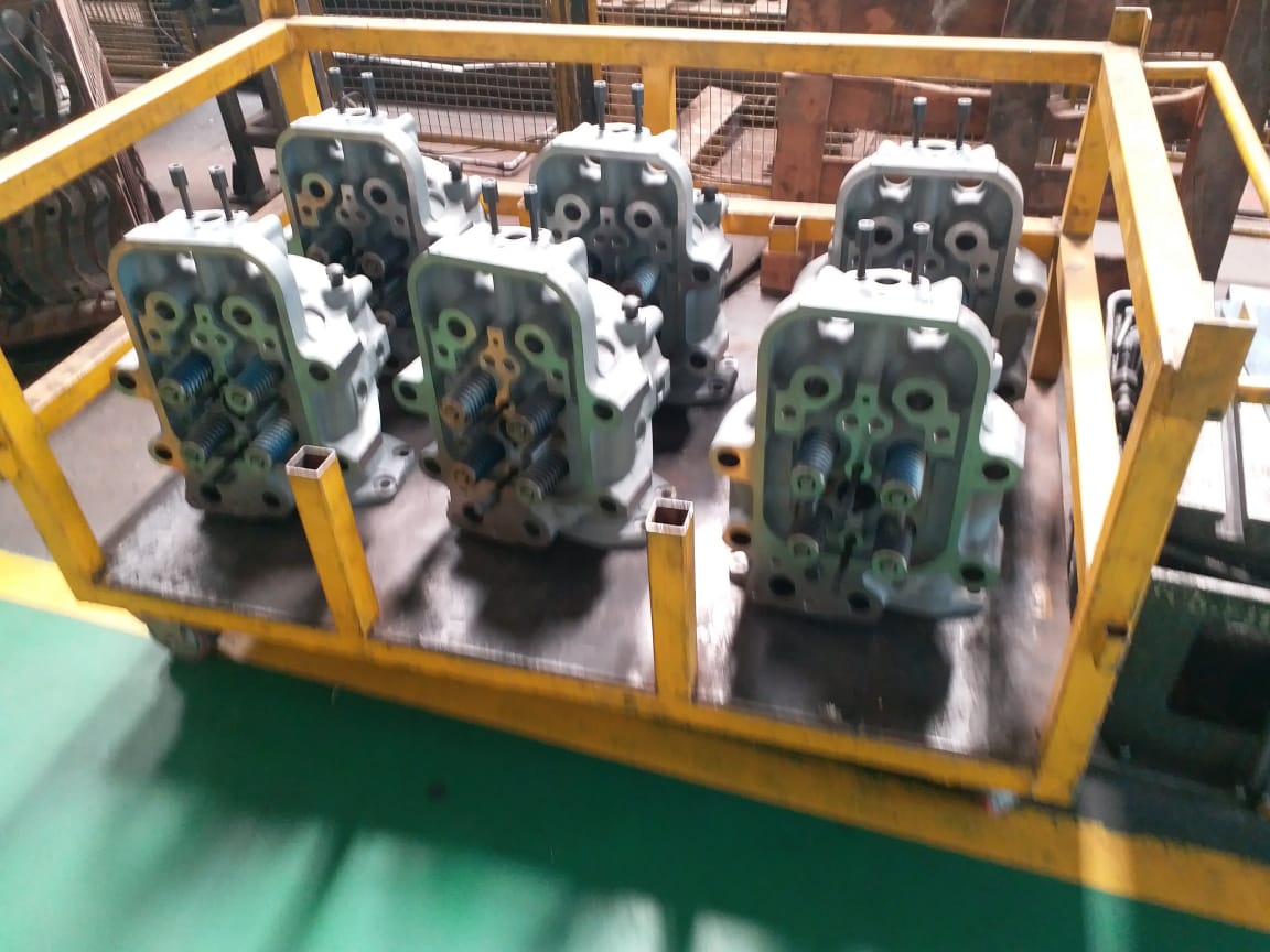
Temperature Range

Considering the cost and life expectancy of the parts is essential, but it’s just as important to take into account the environmental requirements of the equipment. Temperature ranges in particular can play a crucial role in the success of any equipment.

When selecting the right parts for a particular environment, the temperature range should be the first factor taken into consideration. Parts that are exposed to extreme temperatures, either hot or cold, tend to wear out much faster and typically will not last as long as parts in a more temperate environment. In addition, parts that are exposed to temperatures outside their specified range can cause malfunctions and even catastrophic failure.

For instance, a part that is designed to operate at a range of -40°C to +60°C, will not work properly if exposed to temperatures beyond that range. If the temperature is too high, the material can become brittle and crack, leading to premature failure. If the temperature is too low, the material can become brittle and unable to move. In either case, it is important to know the temperature range of the part and make sure it is compatible with the environment.

When selecting parts for a particular environment, it is important to consider the temperature range of the parts. By ensuring that the parts are able to withstand the temperatures in the environment, it not only increases the life expectancy of the parts, but also reduces the risk of malfunctions and catastrophic failure. Taking into account the temperature range of the part is essential when selecting parts for any environment.

Humidity

In addition to the cost and life expectancy of the parts, environmental requirements of the equipment must be taken into account. Of particular importance is humidity. This is due to the fact that high levels of humidity can corrode parts, while low levels can cause components to dry out and become brittle.

Humidity has the potential to cause serious damage to the equipment, and should be monitored closely. A humidity control system should be installed to ensure the environment is within an acceptable range. This system should be designed to maintain the optimal humidity level for the equipment, typically between 40% and 60%.

It is also important to ensure that the humidity level does not fluctate. Sudden changes in humidity can cause condensation to form on the parts, which can lead to corrosion and other damage. Humidity sensors can be used to detect sudden changes in the environment, and corrective measures taken to ensure that the humidity level remains within the acceptable range.

Finally, it is important to note that humidity levels can vary significantly depending on the location of the equipment. Locations with higher humidity, such as coastal areas, should be avoided. It is important to consider the specific environment that the equipment will be operating in when specifying the components and environmental control systems.

Determine the Compatibility of the Parts with Your Existing Equipment

Identifying Parts requires an in-depth assessment of the existing equipment, carefully surveying the components and assessing their compatibility with the new part. Once the components are identified, a thorough examination can be made to determine Compatibility Requirements. Following this, the Electrical Specifications can be evaluated to guarantee that the new part meets the necessary specifications for the existing equipment.

Identifying Parts

Having taken into account the environmental requirements of the equipment, the next step is to determine the compatibility of the parts with the existing equipment. Identifying the components of a system is an important first step in determining compatibility.

The process of identifying parts begins when the user or technician has access to the equipment. Visual inspection can provide the user with a general idea of the parts that make up the system. Additionally, the equipment’s manual and technical drawings can provide detailed information about the various components.

It is important to consider dimensions, connectors, and materials when visually inspecting parts. It is also important to note any warnings or cautions supplied by the equipment manufacturer. These can significantly influence the compatibility of the parts with the existing system and should be taken into account when making decisions.

Finally, labels and markings on the parts can be used to identify the type and model of the components. Specialized tools, such as bar code scanners and RFID readers, can be used to quickly and accurately identify parts. It is important to note that identifying parts can be a time-consuming process and should be done with due diligence to ensure accuracy.

Compatibility Requirements

Having taken into account the environmental requirements of the equipment, the next step is to determine the compatibility of the parts with existing equipment. To ensure compatibility, the necessary technical specifications must be checked. This ensures the parts will operate adequately in the existing system.

Identifying Parts involves examining the type, size, capacity, and electrical requirements of the parts. It is important to know the intended purpose of the part, and any special features associated with it. Italianizing the part number or model number of the part is a good way to track it down and determine its compatibility.

Compatibility Requirements should be checked to ensure the parts will fit in the existing system and work properly with other parts. This includes making sure the voltage, amperage, and power requirements of the parts are compatible with the existing system. It is also important to check that the part is compatible with any special features of the system, such as a particular type of connector or operating system.

The Electrical Specifications of the part must also be checked to ensure it meets the required electrical requirements. This includes making sure the part will operate within the range of voltage and current that is specified for the system. It is also important to make sure the part is compatible with any special safety requirements of the system, such as proper grounding.

In conclusion, compatibility requirements must be checked to ensure the parts will fit in the existing system and work properly with other parts. This includes making sure the voltage, amperage, and power requirements of the parts are compatible with the existing system, as well as any special features of the system. Additionally, the electrical specifications of the part must be checked to ensure it meets the required electrical requirements. This ensures the parts will operate adequately in the existing system.

Electrical Specifications

After taking into account the environmental requirements for the equipment, the next step in the process is to determine the compatibility of the parts with existing equipment. This begins with identifying the specific parts needed for the project, including electrical specifications like voltage, current, and frequency.

The voltage of a part is the amount of electrical potential needed for it to work properly. If the voltage is too low, the part may not have enough power to function, and if the voltage is too high, it could cause the part to malfunction or be damaged. For this reason, it is important to match the voltage of the part to the voltage of the existing equipment.

The current rating of a part is the amount of current it can safely handle. It is typically measured in amperes (amps), and it is important to ensure that the current rating of the part is compatible with the current ratings of the other parts in the system. If the current rating of the part is too low, it may not be able to provide the proper amount of power to the rest of the system, and if the current rating of the part is too high, it could cause other parts to fail.

Finally, the frequency rating of a part is the number of times per second that it can switch on and off, and is typically measured in hertz (Hz). In order to ensure that the parts are compatible, it is important to verify that the frequency rating of the part is in line with the frequency ratings of the other parts in the system. If the frequency rating of a part is too low, it may not be able to provide the necessary amount of power, and if the frequency rating of a part is too high, it could cause other parts to malfunction.

In summary, in order to ensure compatibility of the parts with existing equipment, it is important to verify the electrical specifications of the parts, including voltage, current, and frequency. Careful consideration of these specifications will help ensure that the parts are compatible with the existing system and will help to prevent any malfunctions or damage.

Seek the Advice of an Experienced Technician for Assistance

Searching for a technician can be a daunting task, as there are many available options. It is critical to consult an experienced technician for the best outcome. Taking the time to find a technician who is knowledgeable and reliable can provide many benefits, including access to the latest technology and the assurance of a job done right. Consulting an experienced technician can result in a successful project, providing peace of mind that the desired results have been achieved.

Finding a Technician

Searching for an experienced technician to provide assistance with your existing equipment can be an overwhelming task. Finding a technician with the necessary expertise and qualifications can be difficult if you are not sure where to look. Fortunately, there are a number of different resources to help you find a reliable technician.

One of the best ways to find a reliable technician is to search online. Many professionals have websites that describe their services and provide contact information. Additionally, there are websites that specialize in connecting customers with technicians. These websites may contain reviews of various technicians and can help you narrow down your search.

It is also possible to find a technician by asking for recommendations from friends and family. Many people have had experiences with experienced technicians in the past and can provide valuable insight. Additionally, local businesses may be able to provide contact information for reliable technicians in your area.

Finally, professional organizations are a great way to find experienced technicians. Professional organizations often have directories that list qualified technicians and their areas of expertise. Additionally, many professional organizations hold conventions and other events that provide an opportunity to meet and network with technicians in your field.

Benefits of Consulting a Technician

Having determined the compatibility of the parts with existing equipment, the next step is to seek the advice of an experienced technician for assistance. Consulting a technician provides multiple advantages that can be incredibly beneficial when it comes to the installation and maintenance of machinery.

When enlisting the help of a technician, they can provide expertise in areas such as component selection, part installation, and troubleshooting. Having access to this knowledge and experience can be invaluable in ensuring that the job is done properly and efficiently. This can save the business time and money in the long run.

In addition, technicians can provide advice on the best way to properly maintain the equipment. This can help to extend the life of the machinery and reduce the likelihood of it needing to be repaired or replaced. Furthermore, when repairs are necessary, technicians can identify the source of the problem and complete the repairs in a timely manner.

Lastly, having a trusted technician on call can help to ensure that any unexpected problems that arise can be addressed quickly and easily. This can help to reduce any downtime, which can be costly, and help to maintain customer satisfaction. Overall, the benefits of consulting a technician are numerous and can be incredibly beneficial for any business.

Consulting an Experienced Technician

As you embark on the journey of finding the right equipment for your needs, consulting an experienced technician can provide a wealth of benefits. An experienced technician can provide invaluable advice and guidance on the best solutions to fit your particular needs and budget. Not only can they help you choose the right parts for your existing equipment, but they can also advise you on the installation process and any potential risks associated with the task.

In most cases, consulting an experienced technician is the best approach for ensuring the compatibility of parts with your existing equipment. An experienced technician will have a thorough understanding of the inner workings of various types of equipment and can advise you on the best parts to purchase for your specific model. This can save you time and money in the long run, as you won’t have to replace parts that are not compatible.

Furthermore, an experienced technician can provide valuable advice on installation and potential risks associated with the task. They can provide guidance on the necessary installation tools and techniques to ensure a safe and successful project. They can also tell you which parts will be most effective in the long-term, as well as any potential risks that come with using certain parts.

Finally, consulting an experienced technician can help to avoid any potential hazards associated with the installation. An experienced technician will be able to identify any potential risks that could arise and advise you on the best course of action to prevent them. This can be especially important when dealing with complex or delicate machinery, as any mistakes could lead to costly repairs or replacements.

Overall, consulting an experienced technician is a great way to ensure the compatibility of parts with your existing equipment. Not only can they help you choose the right parts for your model, but they can also provide advice on the installation process and any associated risks. With their help, you can be sure that your project runs smoothly and safely, saving you time and money in the long run.

FAQ

When selecting EMD locomotive electrical parts, several factors should be taken into consideration. Remanufactured parts are often an economical option to new parts, while also offering benefits in terms of performance and reliability. In addition, utilizing EMD locomotive electrical parts can provide a number of advantages, from cost savings to reliability.

1. What Factors Should Be Taken Into Consideration when Choosing Emd Locomotive Electrical Parts?

Having sought the advice of an experienced technician, it is now essential to understand what factors should be taken into consideration when choosing EMD locomotive electrical parts. With this knowledge, one can make an informed decision and confidently invest in the optimal parts for their locomotive.

When selecting EMD locomotive electrical parts, it is essential to consider the part’s function. As EMD parts are designed to fill a specific purpose, it is critical to select a part that meets the requirements of the application. One should also be sure to consider the quality of the part, as the quality can vary among parts of the same type, particularly when comparing new and remanufactured parts.

In addition, the reliability of the part is a crucial factor in selecting EMD locomotive electrical parts. The part should be able to withstand the rigors of locomotive operation and provide consistent, reliable performance. Furthermore, the part’s cost should also be taken into consideration, as certain parts can be more cost-effective than others.

Finally, the availability of the part should be taken into account. Parts that are widely available can provide the necessary convenience for obtaining the part in a timely manner. By taking all of these factors into account, one can make an informed decision and select the EMD locomotive electrical parts that are optimal for their locomotive.

2. What Are the Differences Between New and Remanufactured EMD Locomotive Electrical Parts?

Now that you have sought the advice of an experienced technician for assistance, it is important to understand the differences between new and remanufactured EMD locomotive electrical parts. Remanufactured parts are parts that have been taken apart, inspected, and reassembled with new components as needed. These parts are often easier to find than new parts and can be significantly less expensive. New parts are parts that have never been used before and are often more expensive than remanufactured parts.

The main difference between new and remanufactured parts is the condition of the parts. Remanufactured parts are generally in good condition, but they may have some wear and tear due to their prior use. New parts, on the other hand, are in pristine condition and do not have any signs of wear and tear.

It is also important to consider the functionality of the parts. Remanufactured parts can provide good functionality, but they may not be as reliable as new parts. New parts, however, are more likely to provide better reliability and better overall performance.

Finally, it’s important to consider the cost of the parts. Remanufactured parts are often less expensive than new parts, but they may not last as long. New parts, on the other hand, are more expensive but may last longer. Ultimately, the choice between new and remanufactured parts should be based on the individual needs of the project.

3. What Are the Benefits of Using Emd Locomotive Electrical Parts?

Moving on from seeking the advice of an experienced technician for assistance, let us explore the benefits of using EMD locomotive electrical parts. EMD locomotive electrical parts are designed to be reliable, efficient, and fail-safe, providing the highest levels of performance and dependability. They boast many advantages, including increased durability, improved performance, and cost savings.

For starters, EMD locomotive electrical parts are incredibly durable, thanks to the precise manufacturing processes used in their production. All components are designed to withstand the intense operating conditions of a locomotive engine, and each part is thoroughly tested to ensure that it can withstand the most extreme conditions. This means they can handle the wear and tear of long-term operations without needing to be replaced frequently.

As EMD locomotive electrical parts are designed to be highly efficient, they can generate more power with less fuel, resulting in improved performance and lower fuel costs. Additionally, these parts are designed to be noise-free and require minimal maintenance, meaning there are fewer interruptions to the locomotive operations. This makes them ideal for use in a variety of environments.

Finally, EMD locomotive electrical parts are a cost-effective solution for locomotive operations. They provide a higher level of performance at a lower cost than traditional locomotive parts, and can be easily integrated into existing electrical systems. This makes them an ideal choice for locomotive operators looking to save money on parts and repairs.

In conclusion, EMD locomotive electrical parts offer numerous benefits to locomotive operators, from increased durability and performance to cost savings. With their high levels of dependability and efficiency, they are the ideal choice for any locomotive operation.

Conclusion

When choosing locomotive electrical parts for your needs, it is important to consider the type of part, its specifications, cost, life expectancy, compatibility with existing equipment, and environmental requirements. Additionally, it is beneficial to seek the advice of an experienced technician to ensure the parts are correctly selected and installed. Making the right decision can save time and money in the long run, so proper research and guidance is essential. Asking questions and getting detailed answers can ensure the best results with the right parts for your needs.

Translate »