7 Tips: EMD Locomotive Bearing Tolerance Measurement

7 Tips: EMD Locomotive Bearing Tolerance Measurement

To measure EMD locomotive bearing tolerances accurately, you’ll need precision micrometers and CMMs, keeping tools well-calibrated. Check main bearing bores in 60° increments, verifying dimensions and ellipticity. Use Plastigage for clearance and confirm torque on fasteners with a calibrated wrench. Maintain parallel case surfaces and use alignment gauges for installation. Monitor vibration signatures for early faults. Document measurements against spec. If you want to guarantee top bearing reliability, the next tips detail advanced diagnostic and monitoring methods.

Key Takeaways

  • Use calibrated micron-level micrometers and CMMs to ensure all bearing measurements meet AFBMA and ISO standards for EMD locomotives.
  • Take six radial bore measurements at 60° increments, and confirm bore diameter and ellipticity are within OEM tolerances.
  • Clean all bearing and measurement surfaces thoroughly to prevent contamination errors and inaccurate clearance readings.
  • Apply and verify correct torque values on main bearing and cylinder head nuts; always check torque wrench calibration before use.
  • Document all clearance and roundness measurements, cross-referencing with manufacturer specs, and repeat checks at multiple points to detect taper or out-of-roundness.

Selecting Precision Tools for Accurate Bearing Measurements
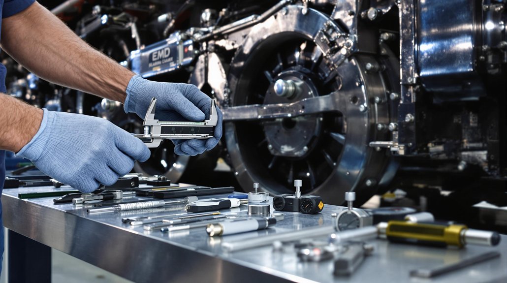
precision tools for measurements

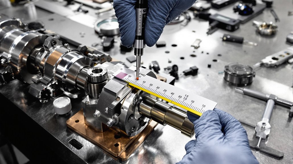
Precision forms the foundation of reliable bearing tolerance measurement in EMD locomotives, making your choice of tools critical for ensuring dimensional accuracy. To achieve ideal measurement accuracy, you’ll need to select instruments that match the stringent requirements of AFBMA and ISO standards. Micron-level micrometers are indispensable when checking bearing sizes and clearances, while ratchet stop micrometers guarantee consistent readings on small dimensions.

For complex geometries, coordinate measuring machines (CMMs) provide precise spatial data, but only if you adhere strictly to calibration techniques and environmental controls—temperature and vibration must be managed.

Because identifying specific bearing type is crucial for accurate measurement, always confirm the type of bearing before choosing your measuring tools and methods.

When inspecting internal diameters, pneumatic air gauges offer non-destructive micro-level resolution, and laser-based tools enable non-contact examination of delicate or large components. Always cross-verify measurements with backup tools and systematically document results. Regular calibration with certified reference standards and disciplined maintenance routines are essential for sustaining measurement accuracy. Only trained personnel should operate these tools to avoid introducing errors.

Ensuring Proper Main Bearing Bore Dimensions
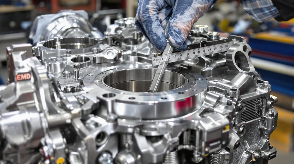
main bearing bore measurements

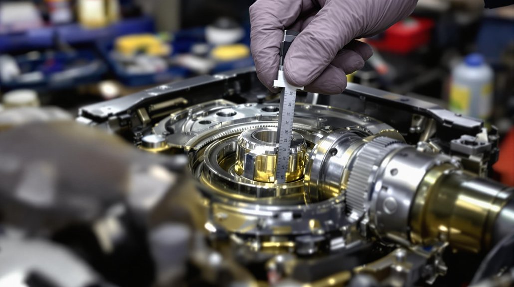
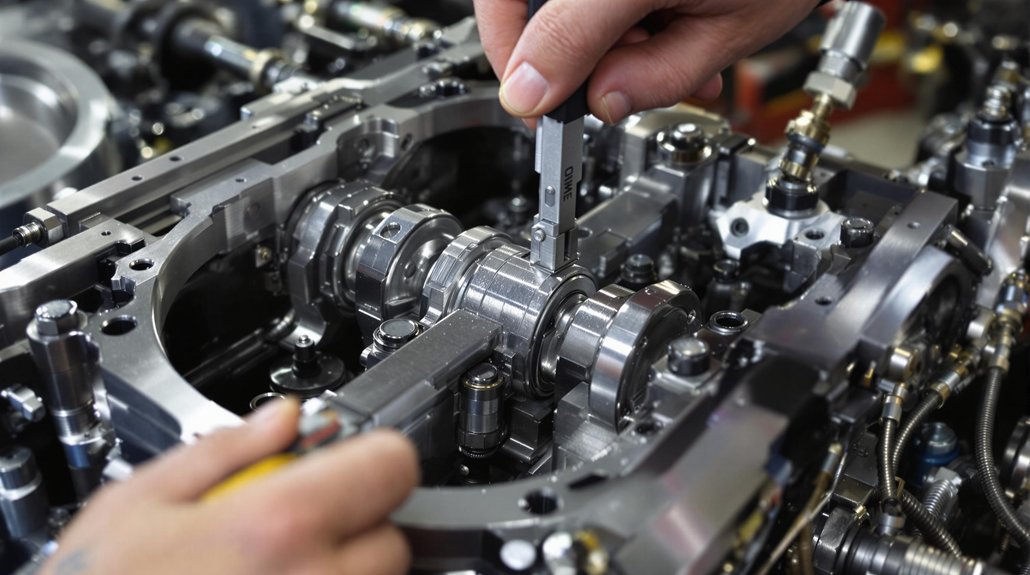
Selecting the right measuring instruments sets the stage for achieving main bearing bore dimensions that meet EMD locomotive standards. You’ll need to check bore geometry by taking six radial measurements—three at each end of the bore in 60° increments. Verify your bore diameter averages between 8.249″ and 8.252″ under a final torque of 650 ft. lbs. Use the main bearing wrench set 82019512 through the oil pan for consistent torque, and employ the offset ratchet set 8191591 for precise nut adjustment.

Maintaining dimensional stability means monitoring out-of-round conditions; your maximum allowable ellipticity is 0.003″ at full torque. Deviation limits define the allowable measurement variations from nominal dimensions, which is crucial for ensuring EMD main bearing bores do not exceed permissible tolerances. Confirm crankcase surfaces are parallel within 0.002″ and that cap bolt torque remains symmetrical to prevent elliptical distortion. Always clean all surfaces before measurement to avoid contamination errors, and use calibrated tools to guarantee accuracy. These steps verify your main bearing bores remain within strict EMD tolerances.

Measuring Clearance With Plastigage and Micrometers
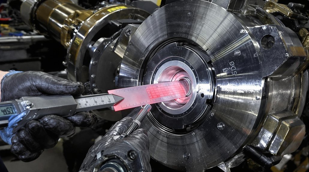
measuring bearing clearance accurately

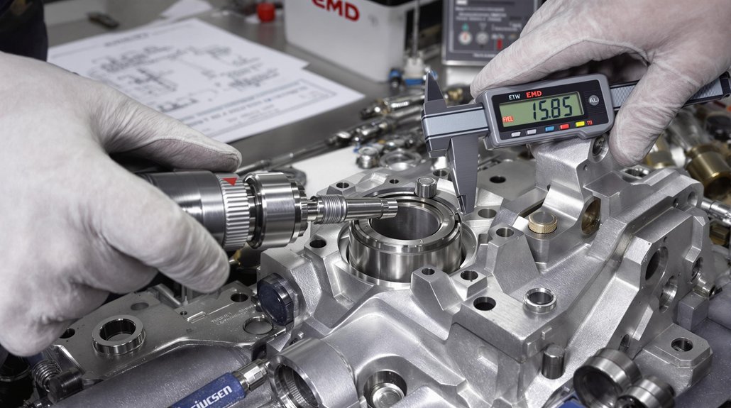
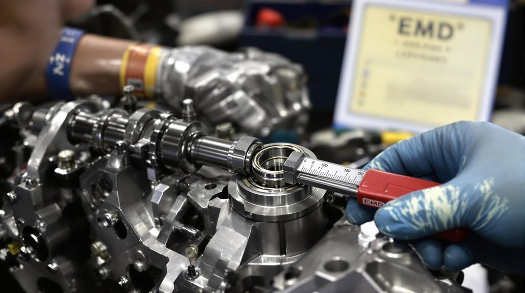
Although main bearing bore dimensions set the foundation, verifying actual bearing clearance demands a careful approach using both Plastigage and micrometers. Start by selecting the correct Plastigage thickness—usually thinner than the expected gap—to avoid compression errors. Clean all bearing surfaces meticulously before Plastigage application, and gently place the strip to prevent inaccurate results. After assembly, compress the Plastigage, then match its width to the reference chart for precise clearance readings. If values fall outside specifications, adjust strip thickness and recheck.

For micrometer-based measurements, confirm micrometer calibration using certified reference bars before taking journal diameters or bore readings. Calculate clearance by subtracting journal diameter from housing bore. Repeat measurements at multiple points to account for taper or out-of-round conditions, always cross-referencing EMD manual tolerances. Regular measurement intervals—often every 1000 hours—help you track wear trends and ensure timely maintenance.

  • Select proper Plastigage and clean surfaces before use
  • Calibrate micrometers and measure at several locations
  • Cross-validate all readings with manufacturer specifications

Applying Correct Torque and Alignment Techniques
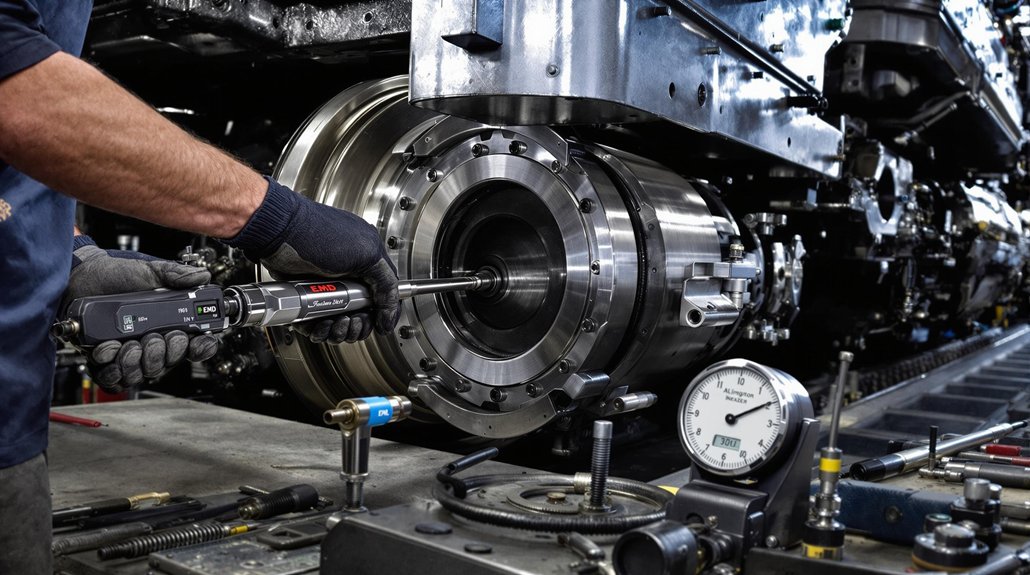
precise torque and alignment

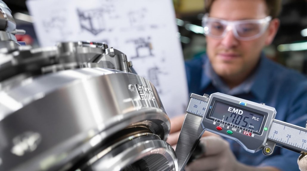
A single misapplied torque or overlooked alignment check can compromise the entire EMD locomotive bearing installation. You must prioritize precise torque application for every critical component. For example, main bearing nuts require 500-800 ft-lbs, but when bore dimensions are between 8.249″-8.252″, use 650 ft-lbs. Cylinder head crab nuts need exactly 1,800 ft-lbs to prevent assembly damage, while fork rod capscrews demand 190-200 ft-lbs, with serration inspection confirming retention. Always verify your torque wrench’s calibration before use, as even minor deviations skew results.

Equally crucial is alignment verification. Use gauge #8177167 to check crankcase serrations, ensuring distortion remains within ±0.003″. Specialized P-pipe alignment tools confirm cooling nozzle positioning; replace misaligned parts immediately. Confirm shaft-to-bearing fit with calibrated micrometers, ensuring proper interference. [Integrating domain and business-oriented factors, as highlighted in Domain Driven Data Mining, can enhance the actionability and reliability of your bearing installation procedures.] Maintain your alignment tools through regular calibration for accurate readings. Thorough torque application and alignment verification are essential for reliable bearing function and long-term locomotive integrity.

Monitoring Vibration Patterns for Early Fault Detection
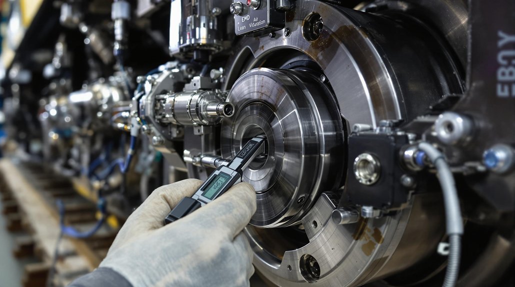
vibration analysis for fault detection

Vibration analysis offers an indispensable window into the early detection of EMD locomotive bearing faults, often revealing issues before they escalate into catastrophic failures. By monitoring high-frequency vibration signatures—particularly in the 25–100 kHz range—you can pinpoint incipient faults long before physical symptoms appear. Key vibration frequencies, such as BPFO (273.17 Hz), BPFI (335.87 Hz), and BSF (125.36 Hz), indicate specific bearing defects and help you localize emerging wear patterns.

Integrating temperature and visual inspection data with vibration analysis increases fault prediction accuracy, especially when advanced methods like Empirical Mode Decomposition (EMD) and machine learning classifiers (e.g., ELM networks) are used to extract and process fault-specific features. EMD signal processing isolates defect-specific frequencies from background noise, allowing for more accurate identification and extraction of fault features during vibration signal decomposition.

  • Track high-frequency vibration bands for earliest fault detection
  • Correlate vibration signatures with temperature and physical wear patterns
  • Apply advanced signal processing for effective fault prediction

Combining multi-sensor data and sophisticated analytics guarantees timely intervention, minimizing costly repairs and downtime.

Validating Tolerances With Manual Measurement Protocols
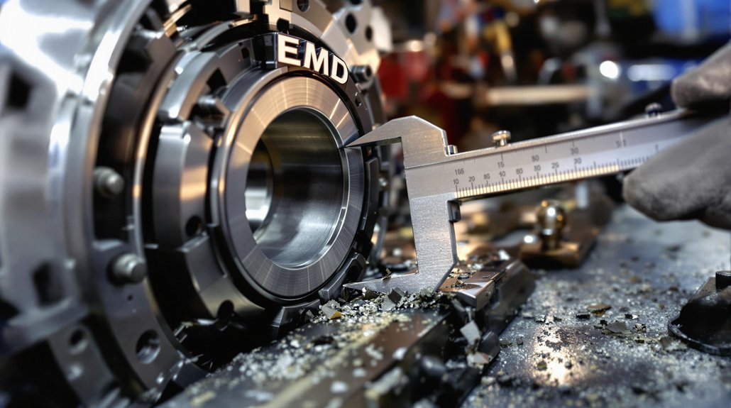
bearing tolerance validation techniques

To validate EMD bearing tolerances, you’ll use multipoint bore measurement methods to capture dimensional consistency across all critical locations. Apply micrometer-based roundness checks to detect any deviation from specified geometry, ensuring the bearing’s structural integrity. Follow strict clearance verification procedures with Plastigage and dial indicators to confirm alignment with EMD’s precise dimensional benchmarks. When working with journal bearings, their high surface area and reliance on hydrodynamic lubrication should be considered during tolerance checks to ensure optimal load distribution and wear compensation.

Multipoint Bore Measurement Methods

Precision underpins effective multipoint bore measurement methods for EMD locomotive bearing tolerance validation. You’ll need to start with rigorous borehole preparation techniques—verify borehole straightness and stability to prevent rod binding. Anchor placement strategies are essential: distribute stainless steel anchors at varying depths, using laser alignment to guarantee accuracy and capture both surface and structural movement. Select the number of anchors based on bore diameter—three for φ76mm, up to six for φ102mm—adhering to minimum φ101mm requirements for sensor stability.

For best results, always assume that the deepest anchor is in stable ground to ensure your displacement measurements are accurate and not influenced by unstable strata. Use fibreglass connecting rods to minimize temperature expansion errors in sensitive environments. Secure the reference head assembly with flange mounting for repeatable, stable measurements. Regularly log manual displacement readings using micrometer gauges and adhere to Abbe’s principle to minimize axis misalignment errors.

These steps guarantee reliable tolerance validation in demanding field conditions.

Micrometer-Based Roundness Checks

After establishing stable multipoint bore measurements, you’ll rely on micrometer-based roundness checks to manually validate EMD locomotive bearing tolerances. Begin by confirming your micrometer calibration against certified reference standards, ensuring sub-thousandth accuracy.

For roundness verification, use a ball micrometer at multiple clock positions—typically every 60°—on the main bearing bore, maintaining specified torque (650 ft. lbs.). The out-of-round tolerance must not exceed 0.003”, with bore diameters between 8.249” and 8.252” post-torquing. Proper liner installation techniques are essential for accurate measurement results, as precision installation techniques help prevent bore distortion and ensure repeatable tolerance verification.] Document all readings and cross-reference them with manufacturer specs. The table below summarizes essential steps:

StepTool/SpecTolerance/Limit
CalibrationReference Standard<0.0005” deviation
Measurement PointsBall MicrometerEvery 60°
Roundness LimitMain Bearing Bore≤ 0.003”

Clearance Verification Procedures

Once you’ve established roundness conformity, clearance verification procedures demand equally rigorous manual protocols to guarantee EMD locomotive bearings operate within strict tolerances. You’ll use Plastigage strips to measure bearing clearances, ensuring values remain in the critical 0.003″-0.005″ range. Precision calipers confirm bearing seat dimensions meet OEM standards, while crankshaft runout is checked with dial indicators for ≤0.002″ deflection. Frequent inspection is essential—bearing wear accelerates rapidly outside these tolerances, so schedule checks according to operational cycles and temperature trends.

  • Verify main bearing and connecting rod cap alignment with specialized gauges during the torque sequence. Regular oil analysis can further enhance predictive maintenance by identifying early signs of bearing contamination or abnormal wear.
  • Record all clearance data and compare it against OEM benchmarks for compliance assurance.
  • Adjust inspection frequency if measurements approach tolerance limits, indicating increased risk of bearing wear.

Leveraging Advanced Diagnostic Technologies for Bearing Health
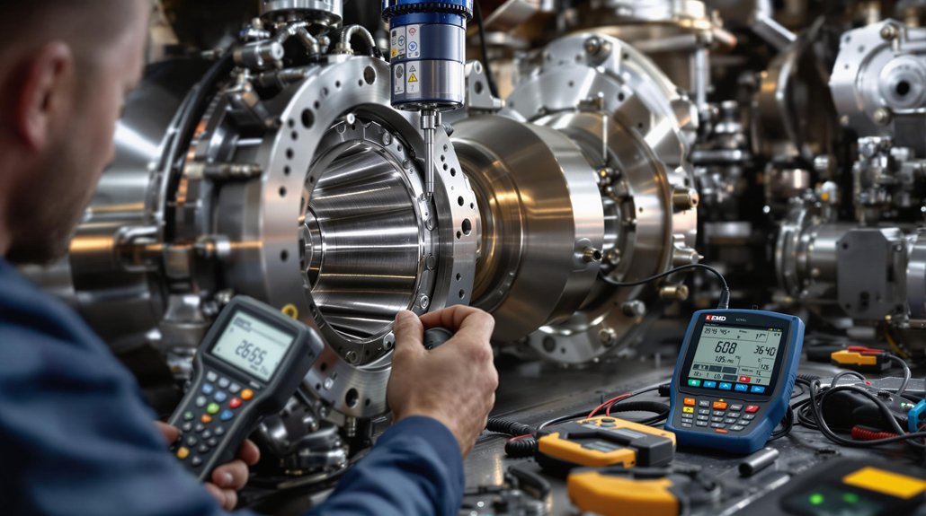
advanced bearing health monitoring

While locomotive bearings operate under harsh and dynamic conditions, advanced diagnostic technologies now allow you to detect subtle signs of degradation long before catastrophic failure. High-frequency vibration analysis (25–100 kHz) isolates early fault-initiation signatures, while envelope power spectrum analysis distinguishes between inner and outer race defects by extracting characteristic frequencies. Variational Mode Decomposition (VMD) and Empirical Mode Decomposition (EMD) decompose complex, non-stationary signals into intrinsic mode functions (IMFs), letting you target fault-specific oscillations despite noise and operational variability.

Multi_correlation Analysis (MCA) further refines detection by prioritizing IMFs with high diagnostic value using metrics like NCM, MIA, and ESC. The integration of EMD and GNN-AdaBoost has also been shown to significantly improve fault diagnosis accuracy in rolling bearings, making it an effective approach for real-time monitoring and predictive maintenance in rail systems. Hybrid approaches integrate thermal and vibration data, correlating temperature deviations (≥10–20°F) with abnormal vibration for a holistic view of bearing health. Wireless data acquisition and adaptive boosting algorithms guarantee real-time, accurate monitoring, even under fluctuating speeds and loads, helping you prioritize maintenance and prevent unplanned downtime.

Frequently Asked Questions

How Often Should Bearing Tolerance Measurements Be Scheduled During Regular Locomotive Maintenance?

You should determine bearing measurement frequency based on your locomotive’s maintenance scheduling and operational demands. For most fleets, schedule tolerance checks every 92 days for basic systems, or every 184 days for advanced platforms. Increase frequency if your units experience high mileage, harsh environments, or after major overhauls. Always align your maintenance scheduling with manufacturer recommendations, ensuring you catch early wear and maintain peak performance. Regular inspections help you prevent costly failures and extend bearing life.

What Are Common Signs of Bearing Tolerance Issues During Locomotive Operation?

Think of a bearing like a heartbeat—when it skips, you sense trouble ahead. You’ll notice tolerance issues when vibration analysis reveals unusual frequency peaks or abrupt amplitude shifts. Maintenance logs might show repeated overheating, increased wear, or oil contamination events. If you spot surface pitting, debris in lubricant, or decreased clearance, act fast. These symptoms signal deeper problems that, left unchecked, can derail schedules and compromise locomotive safety.

Can Environmental Factors Affect Bearing Measurement Accuracy in the Field?

You should always consider environmental factors when measuring bearing tolerances in the field. Temperature fluctuations can cause thermal expansion or contraction, directly impacting your readings and potentially introducing calibration drift in instruments. Humidity levels also play a role—high moisture can lead to corrosion or condensation, distorting measurement points and degrading lubricants. Both factors, if uncontrolled, undermine measurement accuracy, so you need to manage environmental conditions and calibrate your tools accordingly.

When you’re starting out, prioritize online courses focused on bearing tolerance measurement fundamentals and industry standards like ISO and ABEC. Then, supplement your learning with hands-on workshops, where you’ll use micrometers, calibration kits, and torque wrenches. Seek programs offering simulations of real-world scenarios and access to technical documentation. Combine theory with practical exercises, so you’ll understand how to apply tolerance limits, identify wear, and follow correct measurement and inspection procedures.

How Do Bearing Tolerance Issues Impact Overall Locomotive Fuel Efficiency?

You might think ignoring bearing tolerance issues would boost locomotive performance, but it’s quite the opposite. Poor tolerances increase fuel consumption as friction rises, forcing the engine to work harder. Mechanical wear accelerates, leading to frequent maintenance and part replacement. You’ll also see efficiency losses because energy intended for propulsion gets wasted as heat. In short, improper bearing tolerances drain both your fuel budget and your locomotive’s operational reliability.
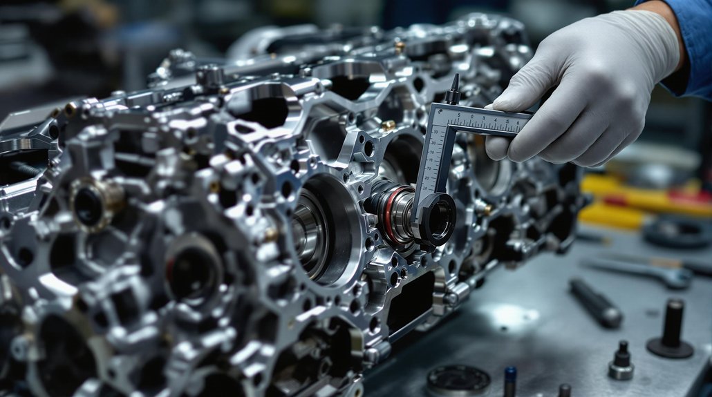
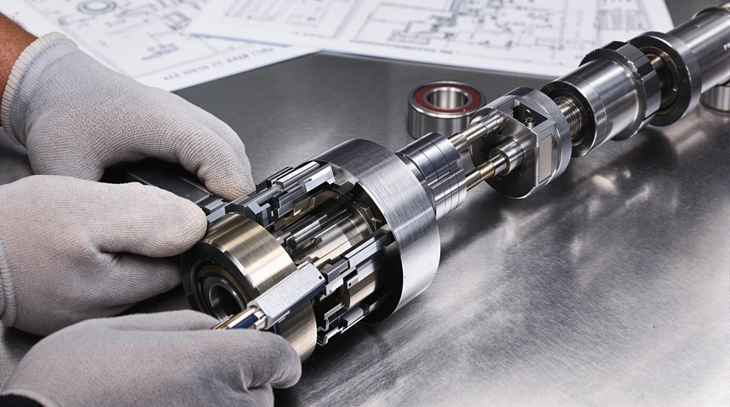
Why Check EMD Camshaft Bearing Clearance Specifications?

Why Check EMD Camshaft Bearing Clearance Specifications?

You need to check EMD camshaft bearing clearance specifications to guarantee you’ve got a proper oil film separating metal surfaces, preventing direct contact and wear. Incorrect clearance—too tight or too loose—risks overheating, oil starvation, or rapid bearing failure. By measuring with precise tools and confirming specs, you maintain ideal lubrication, avoid misalignment, and extend engine life. Following these checks supports reliability and helps you avoid costly failures; there are key techniques and detailed best practices to take into account next.

Key Takeaways

  • Ensures proper oil film formation, preventing metal-to-metal contact and premature camshaft or bearing wear.
  • Verifies correct bearing fit, minimizing risks of seizure, excessive vibration, or engine failure due to misalignment.
  • Detects tolerance stack-up or machining errors that could compromise load capacity and engine reliability.
  • Confirms lubricant viscosity compatibility, optimizing lubrication performance and reducing the risk of oil starvation.
  • Supports preventive maintenance by identifying abnormal wear trends before costly failures occur.

Understanding Critical Clearance Values in EMD Camshafts

optimal emd camshaft clearance

Proper clearance values form the foundation of reliable EMD camshaft operation. When you perform clearance calculations, start with the standard formula—0.00075” to 0.0010” per inch of shaft diameter. For example, a 2.000” shaft requires a baseline clearance of 0.0015”–0.0020”. In high-performance or extreme load scenarios, add 0.0005” to the upper end for added safety. Always account for tolerance stack-ups from the housing, shaft, and bearing materials, as these can introduce up to 0.0026” of variation.

Selecting suitable bearing materials is vital, since each reacts differently under operational stresses and temperature changes. For passenger engines, opt for tighter clearances to minimize noise and vibration, while heavy-duty applications need looser settings for durability. Accurate measurement is critical for engine performance, so using a plastic gauge to check main bearing oil clearance ensures the camshaft remains properly supported and lubricated. Precise clearances guarantee the oil film remains intact, preventing metal-to-metal contact and premature wear. Align your clearance calculations with the bearing material’s properties to optimize both lifespan and operational safety.

Measurement Techniques for Accurate Bearing Clearance

accurate bearing clearance measurement

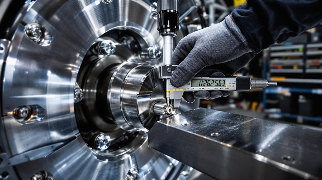
Several essential measurement techniques assure accurate EMD camshaft bearing clearance assessment. Begin by selecting precision measurement tools—dial bore gauges for bearing internal diameter and micrometers with fourth-decimal precision for journal diameter. Always zero and calibrate these measurement tools at 68°F (20°C) to counter thermal expansion effects. Secure bearing caps to their specified torque and assure all surfaces are clean and oil-free for best results.

Proper clearance prevents metal-on-metal contact between engine components, which is critical for ensuring a consistent oil film and long-term reliability.

Measure vertical clearance at 90 degrees to the bearing split line, targeting front, center, and rear positions to identify taper or wear. Remove the camshaft before taking diameter measurements to avoid interference. If using telescopic feeler gauges, never force them; insert the largest size that fits easily to prevent breakage. Plastigage offers a visual method but isn’t as precise as dial gauges—use for quick checks, not critical setups. Meticulously document all clearances in a journal template to track wear trends over time.

The Role of Lubrication in Bearing Longevity

lubrication ensures bearing longevity

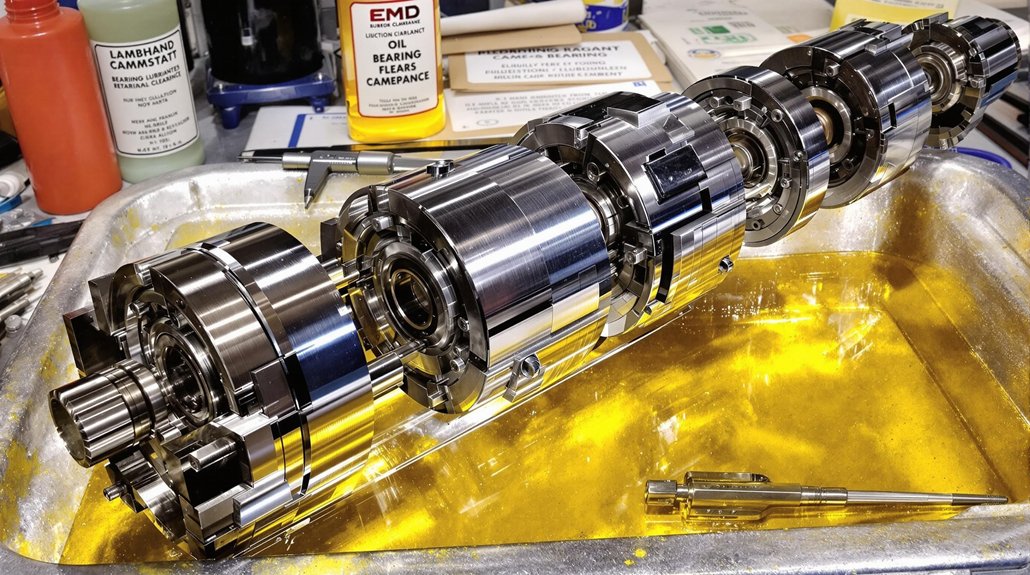
When you assess camshaft bearing longevity in EMD engines, lubrication quality becomes a decisive factor in preventing premature wear. You must verify the lubricant viscosity matches manufacturer specifications to maintain an ideal film thickness between bearing surfaces. This thin oil layer prevents direct metal contact, thereby reducing friction and heat generation. If you choose a lubricant with improper viscosity, you risk inadequate film formation—leading to excessive wear or heat-induced lubricant breakdown.

Always select lubricants based on operational loads, speed, and ambient temperature to ensure consistent flow and protection. Contaminated or low oil contributes to premature wear, making it essential to maintain oil cleanliness and proper levels. Over-lubrication can cause heat buildup, while under-lubrication allows metal-to-metal contact and rapid bearing degradation. Regularly audit lubricant levels and types, adhering to recommended NLGI grades and approved viscosity ranges for EMD camshaft bearings. Precision in lubricant application, contamination control, and ongoing monitoring—such as vibration analysis and thermal imaging—will help you detect early signs of lubrication failure and maximize bearing service life.

Importance of Correct Torque and Installation Procedures

precise torque for reliability

When installing EMD camshaft bearings, you must apply torque precisely according to manufacturer specifications using a calibrated torque wrench. Always follow the correct cap sequencing pattern to guarantee even load distribution and prevent distortion. These steps are critical to maintaining proper bearing clearance and avoiding premature wear. Builders and manuals recommend 15 ft.lbs torque for camshaft bearing caps, as this level helps prevent stripping of studs and ensures long-term reliability.

Precision Torque Application

Precision torque application directly impacts camshaft bearing performance and longevity. When you apply the correct torque to bearing caps and fasteners, you prevent bearing deformation and guarantee the bearing’s inner diameter remains within tight tolerances. If you under- or over-torque, you risk distorting the housing bore, leading to misalignment and uneven force distribution across the camshaft bearing. This not only reduces wear resistance but also compromises the bearing’s load-handling capacity.

Always refer to catalog-specific torque values—such as the 70–2,300 N·m range for MDEU series—and match them precisely to your engine’s specifications. Use calibrated torque tools and follow procedural steps to maintain consistent compression on bearing surfaces. Checking cam bearing housing bores for size and shape before rebuild helps avoid underlying issues that could affect bearing performance, ensuring that torque application delivers the intended benefits. This attention to precision torque protects against premature wear and mechanical failure, optimizing both performance and service life.

Proper Cap Sequencing

Although torque accuracy is essential, the correct sequencing of cap installation plays an equally critical role in guaranteeing proper camshaft bearing clearance. You need to follow a specified bolt pattern—often a cross or staggered method—to avoid uneven pressure that can distort cap alignment. Begin by hand-tightening all bolts, then incrementally apply torque values in the recommended sequence. This prevents local overloading and guarantees the oil film isn’t compromised.

Always verify that the bearing caps’ position markings align precisely with the main journal and oil passages. Use a straightedge to check that each cap maintains proper alignment along the camshaft axis. Performing visual inspection of main caps for correct seating is a key step to ensure accurate assembly. After torquing, inspect for proper seating and confirm that each bearing is fully supported, maximizing load distribution and preventing premature wear or misalignment.

Tolerance and Misalignment Risks in Camshaft Bearings

bearing clearance and alignment

You need to watch for shaft misalignment and compounded tolerance errors, as both can quickly push bearing clearance outside recommended limits. Always verify alignment and measure actual clearances, since even small deviations in housing, shaft, or bearing size stack up and create excessive or insufficient gaps. If you skip these checks, you risk rapid bearing wear, oil starvation, or camshaft seizure. Modern engines require bearings that withstand higher loads and temperatures, so proper clearance is especially important when using stronger, less forgiving materials like aluminum alloys.

Effects of Shaft Misalignment

When camshaft bearings operate under misaligned conditions, the resulting uneven load distribution and increased dynamic stresses can rapidly compromise their integrity. You’ll observe alignment effects such as localized stress concentrations, which accelerate pitting and surface fatigue. Misalignment amplifies edge loading, increasing contact pressures and causing early spalling or cracking. Vibration impact becomes significant, with both radial and axial movements intensifying dynamic forces at the bearing-to-shaft interface.

This not only escalates fretting corrosion and material wear but also generates excessive heat, degrading lubricant viscosity and promoting metal-to-metal contact. As lubricant films erode, friction rises, draining operational efficiency and boosting energy losses. Persistent misalignment leads to premature raceway damage and frequent seal failures, ultimately shortening service life and increasing maintenance demands. Regular monitoring with vibration analysis can help detect subtle changes in machinery performance, allowing for early identification and correction of misalignment before severe bearing damage occurs.

Compounded Tolerance Errors

Even small deviations in camshaft bearing clearances can escalate rapidly due to compounded tolerance errors, especially where shaft, block, and bearing manufacturing variances interact. You’ll encounter tolerance accumulation when block machining, shaft outer diameter, and bearing inner diameter tolerances stack up, pushing clearances outside ideal limits. Aluminum alloy bearings demand strict compliance—material lacks the self-compensation found in babbitt alloys, so any installation errors, such as uneven seating or surface finish irregularities, further skew clearances.

Radial clearance is measured using plastigauge, not thrust clearance, so it is crucial to use the correct method to ensure accurate results. Press-fit and interference designs introduce elastic deformation, complicating post-installation measurements. Contaminants in bearing bores or unfinished bearing seats also contribute to unpredictable clearance loss. If you don’t systematically verify with precise tools, compounded errors can increase wear, reduce load capacity, and jeopardize the camshaft’s operational reliability.

Effects of Clearance Deviations on Engine Performance

clearance deviations affect performance

Although camshaft bearing clearance may seem like a minor specification, deviations from prescribed tolerances have immediate and far-reaching effects on engine performance. When you exceed recommended clearances, the primary clearance impact is reduced load capacity, resulting in accelerated material fatigue and overlay cracking. Fatigue cracks propagate to the steel lining, fragmenting the bearing and degrading its structural integrity—especially in turbocharged engines. Excessive clearance also creates oil leakage during cold starts, risking lubrication starvation and lifter malfunction.

Conversely, too little clearance restricts oil flow, increasing friction and heat generation. This thermal stress accelerates bearing wear and shortens component lifespan. On the timing side, increased bearing movement introduces valve phase errors, delaying valve events and reducing combustion efficiency. The cumulative effect undermines power output and responsiveness, particularly in high-compression configurations. By maintaining precise camshaft bearing clearance, you directly support performance optimization, engine reliability, and minimize costly unplanned maintenance. Typical minimum clearance around .006 is observed in older engines, indicating that both excessive and insufficient clearance can have measurable impacts even in long-running, high-mileage engines.

Lubricant Selection and Oil Submergence Guidelines

lubricant selection and submergence

Selecting the correct lubricant and establishing appropriate oil submergence are critical steps in guaranteeing ideal camshaft bearing performance. You need to match lubricant properties—especially viscosity—to the measured bearing clearance. For example, 5w20 oils suit clearances below 0.0021″, while 20w50 oils require clearances above 0.0031″. Using high-viscosity oil with minimal clearance increases temperatures and accelerates oxidation, risking lubrication failure. Conversely, low-viscosity oils with excessive clearance can’t maintain an adequate oil film, leading to metal-to-metal contact.

Oil submergence must be sufficient to keep bearings continuously supplied, preventing starvation during high-load or transient conditions. Confirm the oil level allows for proper circulation without aeration or foaming, as both degrade lubricant properties. Always adjust oil submergence based on operating conditions and engine design. By precisely aligning lubricant properties and oil submergence to your camshaft bearing clearances, you’ll optimize thermal control, lubrication efficiency, and long-term component reliability.

Maintenance Strategies for Sustaining Proper Bearing Clearance

bearing clearance maintenance strategies

To sustain proper camshaft bearing clearance, you must implement a disciplined combination of precise measurement, systematic inspection, and controlled installation practices. Start bearing maintenance by measuring crankshaft runout with dial indicators, ensuring it stays within a 0.002″ tolerance. Use Plastigage strips to verify that bearing clearance meets the 0.003″–0.005″ specification. Confirm bearing wall thickness with ball micrometers to detect wear or deformation. Adhere to proper torque values—use calibrated wrenches and follow specified patterns to achieve uniform stress on main and rod bearings.

Increase inspection frequency as components age or in high-load environments. Conduct visual inspections for water contamination, dirt scratches, and overlay flaking, referencing standardized criteria. Clean cap bores and serrations before installation to prevent misalignment. Cross-check fitment with alignment tools and validate component dimensions against OEM data. Log all clearance measurements, torque readings, and defect codes to support trend analysis and future preventive actions, ensuring long-term camshaft reliability.

You may also like to read – Symptoms of Worn Camshaft: Epic Signs for Better Diagnosis

Frequently Asked Questions

How Often Should EMD Camshaft Bearing Clearances Be Checked During Service?

You should follow camshaft service frequency and clearance inspection intervals as outlined in EMD’s maintenance guidelines. Typically, check camshaft bearing clearances during every scheduled major overhaul, after any component replacement, or if you notice abnormal engine performance. Always inspect clearances after reassembly or alignment adjustments. Regularly documenting these intervals guarantees you catch excessive wear early, maintain factory tolerances, and prevent unexpected failures, keeping your engine running reliably between service cycles.

What Are the Signs of Camshaft Bearing Clearance Issues During Engine Operation?

You’ll notice camshaft bearing clearance issues by listening for unusual camshaft noise, like clunking or tapping, especially near the valvetrain. Monitor oil pressure closely—if it drops, it can indicate excessive clearance or bearing wear. Watch for a check engine light, power loss, or engine backfiring. Inspect oil for metallic particles, and check for increased oil consumption or leaks near bearing areas, all pointing to potential clearance problems.

Can Bearing Clearance Adjustments Be Made Without Engine Disassembly?

Think of your engine as a sealed vault—bearing adjustment is like trying to fix a lock from the outside. You can’t make precise bearing clearance adjustments without engine disassembly because access to camshaft journals and bearings is blocked. For proper engine maintenance, you must remove and inspect components, measure clearances with specialized tools, and fit appropriate shells. Skipping disassembly risks inaccurate bearing adjustment and potential long-term engine damage.

Yes, you’ll find several recommended aftermarket gauges and precision tools for measuring EMD camshaft bearing clearance. Use plastic strip gauges for quick, visual clearance checks, but rely on precision micrometers and dial bore gauges for high accuracy. Pair these with dial indicators and bearing serration gauges to assess cap distortion and serration alignment. Always calibrate your precision tools before use and follow EMD-specific measurement procedures for best results and compliance.

What Training Is Required for Technicians Measuring EMD Camshaft Bearing Clearances?

To measure EMD camshaft bearing clearances accurately, you need hands-on experience with precision tools like micrometers, bore gauges, and dial indicators. Certification programs train you in reading EMD technical manuals, performing vertical and thrust clearance checks, and following torque specs. You’ll learn assembly validation, proper bearing material handling, and measurement protocols. Cross-training in tribology guarantees you understand oil film dynamics, so you can troubleshoot and maintain ideal clearances effectively.

Translate »