The top EMD power assembly rebuild kits include Premium 645E Series Overhaul Kits, 16-645E3 Power Assembly Solutions, and EconoLife kits for aging locomotives. You’ll find extensive options with enhanced gaskets, temperature-resistant materials, and specialized lubrication systems. Look for kits offering extended warranty protection, single-SKU inventory solutions, and factory-certified installation packages. The best rebuilds feature diagnostic compatibility and exceed OEM standards for performance. Continue for detailed comparisons of each solution’s unique advantages.
Key Takeaways
- Premium EMD 645E Series Overhaul Kits provide all-inclusive components for locomotive power assembly rebuilds with enhanced cooling passages.
- Top-performing 16-645E3 Power Assembly Solutions offer extended warranty protection packages covering parts and labor for up to 36 months.
- EconoLife Power Assemblies deliver cost-effective alternatives for aging locomotives while maintaining required performance standards.
- Advanced gasket technologies feature high-temperature resistant materials that maintain thermal stability up to 427°C.
- EMD’s UL Power Assemblies achieve 50% lube oil savings with dual-stage centrifugal filtration systems.
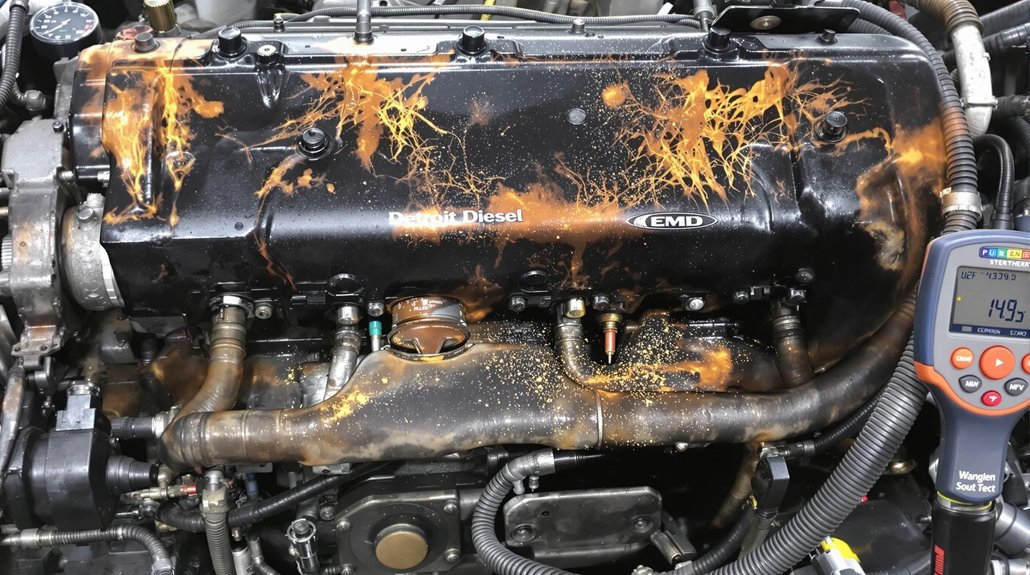
Premium EMD 645E Series Overhaul Kits

Premium EMD 645E Series Overhaul Kits deliver extensive solutions for your locomotive power assembly rebuilds. These all-inclusive packages contain precisely engineered components for the critical power assembly elements: cylinder heads, liners, and pistons. Each component is manufactured to exacting specifications, guaranteeing peak engine performance after installation.
You’ll appreciate the durability these kits provide, extending intervals between maintenance schedules while maintaining operational reliability. The cylinder heads feature enhanced cooling passages and reinforced valve seats, while the liners incorporate improved wear surfaces to resist scuffing and scoring. Understanding the different cooling system configurations is essential when selecting the appropriate overhaul kit for your specific EMD model.
When selecting these kits, you’re investing in components designed specifically for the EMD 645E platform. This compatibility eliminates guesswork during rebuilds and guarantees proper fit and function. The pistons include advanced ring technology that reduces oil consumption and improves compression, directly contributing to better fuel economy and reduced emissions throughout your locomotive’s service life.
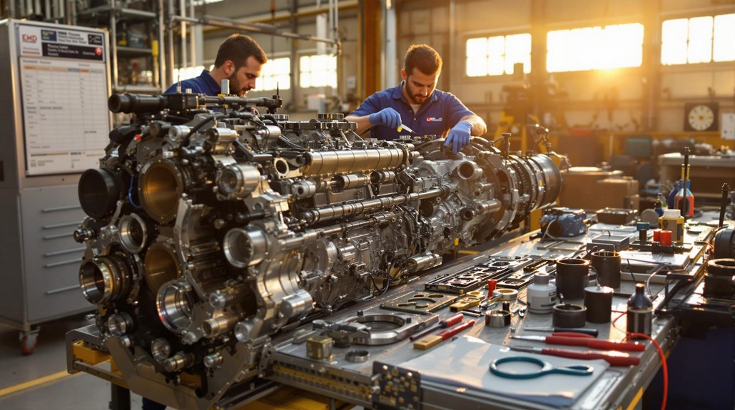
Top-Performing 16-645E3 Power Assembly Solutions

You’ll maximize fleet uptime with our top-performing 16-645E3 power assemblies that include extended warranty protection packages covering parts and labor for up to 36 months. Our streamlined inventory management system guarantees critical components arrive just-in-time, eliminating costly parts shortages during scheduled maintenance events. Each assembly features enhanced durability components, including high-temperature resistant gaskets and precision-machined pistons that greatly extend service intervals beyond standard OEM specifications. These assemblies are specifically designed for switch duty service where maintenance cost reduction is the primary focus.
Ultimate Warranty Protection Packages
Three distinct warranty tiers form the foundation of our Ultimate Protection Packages for 16-645E3 power assemblies, each designed to match your operational requirements. The EconoLife package provides basic coverage for tie-on exempt engines, ideal when you’re prioritizing cost-effective solutions for older fleets.
For maximum warranty benefits, choose our OEM-backed packages that guarantee emissions and performance compliance—crucial if you’re operating Tier 0/0+-certified equipment. PowerRail’s quality assurance ensures all power assemblies exceed OEM standards for reliable performance. These premium protection strategies guarantee your power assemblies work seamlessly with calibrated fuel injectors and turbochargers.
Unlike third-party options with undefined performance parameters, our warranties cover complete system integration without compromising emissions standards. You’ll receive full documentation supporting your compliance requirements, whether for Rail (E4/E4B/E10B) or Marine applications, eliminating the risk of EPA Part 1033 violations.
Streamlined Inventory Management
While maintaining an ideal inventory of EMD power assembly components presents significant challenges for fleet managers, our streamlined 16-645E3 solutions eliminate common supply chain bottlenecks. Our EconoLife™ power assemblies in fork, blade, and partial pack configurations reduce your storage requirements while simplifying handling operations.
Our inventory optimization system incorporates multi-layered part numbering that distinguishes between OEM (9580770), Dinex (DE13018), and HP codes for thorough tracking. You’ll benefit from standardized packaging with pre-assembled kits for both old and new CTVS styles, reducing installation time. Our comprehensive inventory includes various turbocharger part numbers specifically designed for EMD locomotive applications.
Cost analysis demonstrates significant savings with our unit exchange programs that provide instant availability of critical components. PowerRail’s M-1003 certified components guarantee interchangeable parts with OEM quality while our conditional inventory management anticipates your needs based on locomotive duty cycles.
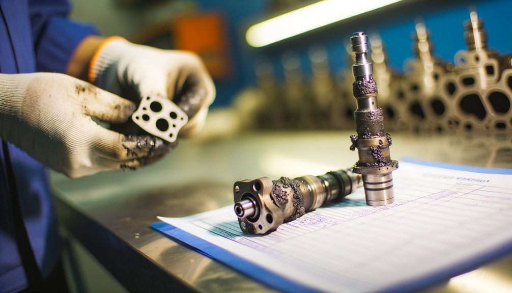
Enhanced Durability Components
Our advanced Swellex Enhanced Material Solutions deliver exceptional service life for EMD 16-645E3 power assemblies under demanding operational conditions. You’ll benefit from multi-layer gasket kits with integrated seals for critical engine interfaces, including head-to-liner configurations that incorporate grommet seals for superior thermal resistance.
Choose from Swellex+ and HP variants specifically engineered through rigorous durability testing to withstand high-pressure applications. These components demonstrably extend component longevity in heavy-duty service environments. For retrofit applications, our CTVS-style power assembly kits support both old and new installation configurations.
The complete solution includes specialized lube oil strainer replacements with element and suction strainer kits. All components offer compression ratio flexibility of 16 and can be configured in fork, blade, or partial pack arrangements.
Cost-Effective Rebuild Options for Aging Locomotives

When maintaining aging locomotive fleets with tightening operational budgets, finding cost-effective power assembly rebuild options becomes essential for extending service life without capital replacement. EconoLife™ Power Assemblies offer practical cost saving alternatives for older EMD® 645E switch duty applications where premium performance isn’t required. Modern data engineering practices incorporate ETL processes to automate and streamline equipment maintenance tracking across large fleets.
| Component Type | Budget Option | Mid-Tier Solution |
|---|---|---|
| Power Assemblies | EconoLife™ (16:1 ratio) | Clark Industrial Compatible |
| Complete Kits | Partial Packs | Turbo Parts World Bundled Kits |
| Pistons/Liners | Standard Replacement | Premium Laser-Hardened Liners |
These efficient repair strategies include choosing appropriate compression ratios (14.5:1 with rocking pins can replace 645E3 assemblies) and pre-packaged thorough overhaul kits that minimize bespoke procurement. While these options aren’t typically certified for EPA Tier compliance, they provide economical solutions for non-exempt engines requiring running repairs of individual failures.
Heavy-Duty Gasket Sets for Extended Service Life

When rebuilding EMD power assemblies, you’ll need heavy-duty gasket sets that incorporate specialized composite materials like thermoplastic elastomers for superior sealing performance. Temperature-resistant sealing solutions, including stainless steel components and heat-resistant rubber compounds, help maintain integrity through the extreme thermal cycling common in locomotive operations. Strategic compression designs featuring zero-gap fitment and anti-condensate properties guarantee your rebuild maintains proper sealing under the high-pressure conditions of extended service life. Similar to the LifePlus Gaskets, these specialized gaskets offer longer life span than traditional alternatives, providing exceptional value for power assembly rebuilds.
Specialized Composite Materials
Engineered for extreme pressures and thermal cycling, EMD Power’s heavy-duty gasket sets incorporate advanced composite materials that dramatically extend service intervals. You’ll find these material innovations deliver superior sealing under the most demanding conditions, with composite advantages including enhanced crush resistance and zero torque loss. These specialized materials guarantee your EMD power assemblies maintain seal integrity throughout demanding operational cycles. The comprehensive material technology ensures optimal sealing performance under varied operational conditions.
| Material Type | Temperature Range | Application Benefits |
|---|---|---|
| MLS with Polymer Coatings | Up to 1500°F | Prevents fluid seepage, reduces bore distortion |
| Aramid-NBR Blends | Up to 800°F | 27.59 psi crush resistance in TN-9005/TS-9016 |
| Graphite-Reinforced | Up to 1800°F | No creep under extreme temperatures |
| Enhanced NBR | Up to 300°F | Superior fuel/oil resistance in transmission systems |
| Reinforced Cellulose | Up to 500°F | Ideal compressibility with 1.33-1.36 density |
Temperature-Resistant Sealing Solutions
The specialized composite materials in EMD’s kits reveal their true value when facing extreme thermal challenges. You’ll find high-performance polymers like silicone and PTFE gaskets maintaining thermal stability solutions up to 427°C, while ceramic fiber materials handle temperatures exceeding 1260°C in critical sealing zones. These materials are carefully selected for their durability and heat resistance, matching the same qualities found in cylinder liner construction.
For superior seal integrity technologies, look for DRI-ETG SWG gaskets with serrated grooves that enhance radial strength at high temperatures. The HT1000 gaskets utilize dual-layer design with mica-loaded surfaces to limit heat transfer, preventing adjacent component failures. VPS YellowSeal™ gaskets incorporate Viton® compounds with collared I.D. rings that stabilize sealing faces during thermal cycling. EMD’s controlled swell technology guarantees these gaskets expand when exposed to media, effectively sealing micro-imperfections without compromising long-term performance.
Strategic Compression Designs
Strategic compression designs in EMD’s heavy-duty gasket sets deliver exceptional service life through innovative material layering and stress distribution. You’ll achieve ideal sealing with multi-layer constructions that combine full-hard stainless steel facings and elastomeric materials, balancing structural integrity with compression resilience. Regular inspection of these gaskets helps detect visible flattening that could indicate potential failure.
Advanced gasket optimization incorporates LaserWeld™ stopper layers and hourglass-shaped reinforcements that distribute clamp loads evenly across flange surfaces, preventing localized deformation. Pre-molded reinforcement rings effectively prevent over-compression during installation.
For maximum effectiveness, implement compression techniques like sequential bolt tightening and torque control systems. These guarantee uniform stress distribution while maintaining proper compression limiters that preserve the gasket’s elastic recovery capacity. Follow surface preparation standards with Ra finishes ≤80 µin for elastomeric-coated gaskets to ensure ideal sealing performance in your EMD rebuild.
Specialized Lubrication System Enhancement Packages

While conventional lubrication systems provide basic protection, specialized lubrication system enhancement packages deliver measurable performance improvements across multiple critical parameters. IOW Group’s advanced lubrication technology combines dual-stage centrifugal filtration with automatic backflush systems to remove contaminants traditional filters miss.
You’ll achieve 50% lube oil savings through EMD’s UL Power Assemblies with their hardened upper bore liners and advanced ring designs. The integration of tin-plated pistons with hardened ring grooves dramatically reduces scuffing while preventing oil breakdown.
For enhanced performance, consider upgrading to VPS YellowSeal Technology with Viton® gaskets that resist contamination and fracturing. Pair this with pressurized drain systems that accelerate oil return to sumps, preventing sludge buildup. The IOW MP600 centrifuge effectively removes sub-micron level contaminants that would otherwise cause long-term wear and reduce engine lifespan. These thorough upgrades extend component life while considerably reducing maintenance intervals—a critical advantage for high-demand operations where unscheduled downtime isn’t an option.
Advanced Diagnostic-Compatible Rebuild Components

Your EMD rebuild kit’s diagnostic compatibility enables real-time engine performance monitoring through integrated sensor ports and calibrated measurement points. Modern kits feature centralized error reporting systems that consolidate fault codes from multiple subsystems into standardized diagnostics displays. These advanced components allow you to identify potential failures before they occur, greatly reducing downtime and extending the service life of your EMD equipment.
Real-Time Performance Monitoring
Modern EMD power assembly rebuild kits now incorporate sophisticated real-time performance monitoring capabilities that transform maintenance from reactive to predictive. These systems track critical parameters including active energy, power, voltage, current, and power factor through customizable sensor arrays that support 4-12 analog/digital inputs.
You’ll benefit from real-time analytics that stream performance metrics via cellular or Wi-Fi connectivity to cloud platforms, where data is aggregated into actionable categories. The replaceable sensor modules attach quickly to EMD assemblies, minimizing downtime during rebuilds. For performance optimization, these systems employ fault detection algorithms that analyze operational patterns against millions of hours of baseline data. The health scoring systems provide numerical reliability indices, helping you identify gradual degradation in components before catastrophic failures occur. This intelligent monitoring guarantees maximum uptime while reducing overall maintenance costs.
Centralized Error Reporting
Advanced EMD rebuild kits now feature extensive centralized error reporting systems that dramatically enhance diagnostic capabilities across platforms. You’ll benefit from native UDS integration and OBD-II/CAN compliance, guaranteeing your diagnostic tools interface seamlessly with rebuilt components.
These kits implement sophisticated error classification systems with tiered severity levels, optimizing your troubleshooting workflow. The centralized diagnostics capture environmental data alongside error events, providing context-specific metrics critical for precision repairs. DTC standardization follows the 24-bit format with status masks per UDS specifications, making error interpretation consistent.
What sets premium rebuild components apart is their fault memory structures designed for AI-ready analysis. Error aggregation algorithms automatically consolidate recurring faults, helping you quickly identify systemic issues rather than chasing symptoms. This centralized error reporting architecture guarantees compatibility with AUTOSAR diagnostic systems for thorough oversight.
Complete Power Assembly Restoration Systems With Warranty Coverage
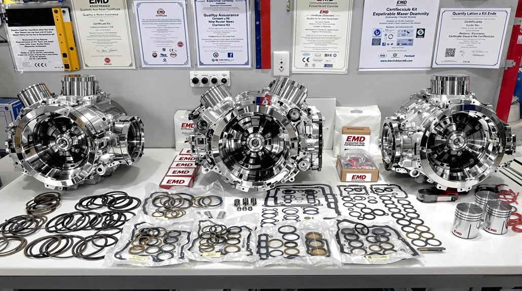
Complete power assembly restoration systems offer three essential benefits for EMD operators: pre-packaged component inclusion, customizable configurations, and extensive warranty protection. You’ll avoid costly downtime with thorough kits containing all bearings, gaskets, seals, and fasteners needed for your specific engine compatibility.
Technical sales managers will collaborate with you to design rebuild solutions tailored to your exact specifications and maintenance schedules, ensuring peak performance and warranty benefits.
| Feature | Benefit | Impact |
|---|---|---|
| Pre-packaged components | Zero missing parts | Eliminates rebuild delays |
| Application-specific kits | Single SKU simplicity | Reduces inventory complexity |
| Adjustable configurations | Meets unique requirements | Maximizes operational efficiency |
These systems include end-to-end technical support with transportation, installation supervision, and SCADA integration options. High-strength materials improve structural lifespan while reducing your overall maintenance costs, all backed by extensive warranties that protect your investment throughout the restoration lifecycle.
Single-SKU Solutions for Streamlined Inventory Management

Single-SKU management revolutionizes EMD power assembly rebuilds by eliminating the complexity that plagues traditional multi-component ordering systems. With attribute-based SKU design, you’ll track all variations—whether piston rings, liners, or injector components—under one parent identifier while maintaining visibility into each sub-component.
Implementing inventory consolidation strategies through unified catalog management allows seamless integration between your FBA/FBM fulfillment methods and warehouse operations. Your team can instantly identify which rebuild kit components need replenishment through real-time tracking systems with automated alerts when stock levels drop below predetermined thresholds.
The SKU standardization benefits extend beyond organization—they directly impact profitability. Advanced forecasting algorithms analyze historical EMD kit sales data, automatically adjusting reorder points based on seasonality and demand patterns. This eliminates redundant parts while ensuring you maintain ideal stock levels of high-turn components.
With centralized data analysis across sales channels, you’ll gain unprecedented visibility into which power assembly configurations deliver the highest margins and customer satisfaction rates.
Material-Optimized Seal Kits for Extreme Operating Conditions

Extreme environmental challenges demand seal kits specifically engineered for EMD power assemblies operating in harsh conditions. When selecting rebuild components, your material selection strategy must prioritize high-temperature resistance and radiation tolerance. Our material-optimized seal kits feature fluoroelastomer (FKM) compounds and composite-enhanced PTFE with carbon fiber and graphite additives for superior thermal conductivity.
Our seal design innovations directly address extreme operating environments through:
- Adaptive sealing structures that dynamically adjust sealing force under fluctuating pressures and temperatures
- Wide-temperature compensation using corrugated PTFE structures capable of maintaining integrity from -196°C to 320°C
- Hybrid PTFE/elastic systems combining glide elements with specialized energizers for multi-condition compatibility
For critical applications, we incorporate Inconel alloys in metal O-ring configurations, achieving nanoleakage capacities of 1×10⁻¹⁰ cc/sec—essential for maintaining system integrity under extreme pressure differentials. Every kit undergoes rigorous testing protocols to guarantee dimensional accuracy and material conformance.
Factory-Certified Installation Fixture Packages

Factory-Certified Installation Fixture Packages represent the foundation of proper EMD power assembly rebuilds. These packages deliver substantial factory certified benefits through components exclusively sourced from OEM supply chains, ensuring authenticity and compatibility with your equipment. You’ll receive parts with guaranteed long-term availability—most components remain accessible for 15+ years.
When you choose certified packages, you’re accessing installation expertise developed through rigorous technician screening and specialized training at manufacturer headquarters. This technical proficiency translates to precision diagnostics and seamless integration of components.
Your investment is protected with an additional year of warranty coverage and extensive replacement guarantees covering both labor and materials. The certification program includes customized pre-installation consultations to assess site requirements and minimize operational disruptions during service.
For complex rebuilds, you’ll appreciate the dedicated project managers overseeing the integration process, complete with thorough post-installation verification to confirm peak functionality of your power assembly.
Frequently Asked Questions
How Do EMD Power Assembly Kits Perform in Extreme Temperature Environments?
EMD power assembly kits excel in extreme temperature environments through their advanced thermal management. You’ll benefit from multi-pass aftercoolers and enhanced cooling passages that maintain temperature resilience in high-heat conditions. The corrosion-resistant materials withstand thermal stress while optimized surface finishes minimize thermal resistance. These assemblies perform consistently in extreme conditions from sub-zero to intense heat, maintaining efficiency and reliability without compromising operational integrity or component longevity.
Can Rebuild Kits Be Custom-Configured for Unique Locomotive Operating Profiles?
Like a bespoke suit tailored to your measurements, EMD power assemblies can be custom-configured to match your locomotive’s unique operating profile. You’ll find custom assembly options based on your specific locomotive specifications, including compression ratios adjusted for elevation, fuel injector patterns for load profiles, and bearing configurations for stress patterns. Your rebuild kit can incorporate specialized turbocharger options and cooling systems calibrated for your exact duty cycle and environmental conditions.
What Training Is Required for Technicians Installing These Kits?
You’ll need extensive technician certification through EMD technical courses covering engine systems and major components. Your training must include hands-on experience with installation techniques for power assembly change-outs, using torque screwdrivers and dial indicators precisely. You’ll practice disassembly/reassembly under supervision and learn troubleshooting procedures. PPE compliance is mandatory, and you’ll undergo periodic competency assessments while maintaining access to updated EMD maintenance documentation for continued skill development.
How Do Aftermarket Kits Compare to OEM Parts for Reliability?
While some aftermarket kits claim equivalent performance, they typically lack the precision engineering that guarantees OEM longevity. You’ll find aftermarket quality varies considerably—some components may achieve 60-70% of OEM lifespan, but critical elements often miss proprietary features like EMD’s induction-hardened valve seats or optimized cooling configurations. Your most reliable option remains genuine OEM assemblies, which deliver verified material quality, consistent dimensional tolerances, and manufacturer-backed warranties that protect your substantial investment.
Are There Environmentally Sustainable Components Available in Modern Rebuild Kits?
Yes, modern rebuild kits now incorporate green materials and eco-friendly practices. You’ll find carbon fiber components that reduce weight and fuel consumption. Additive manufacturing minimizes material waste during production. EPA-certified emissions kits decrease NOx and particulate matter while optimizing fuel efficiency. These kits also reduce lube oil consumption, minimizing environmental impact. High-strength alloys extend component life, reducing the frequency of rebuilds and associated resource consumption.