Air Inlet Casing for Locomotive Engines: Enhancing Turbocharger Intake Efficiency

Air Inlet Casing for Locomotive Engines: Enhancing Turbocharger Intake Efficiency

Introduction

The air inlet casing helps turbocharged train engines work better and use less fuel. The engine gets enough clean air to optimize power output during combustion. This article discusses why the air inlet casing is important for locomotive engines. It also explains how it improves turbocharger intake efficiency.

Importance of air inlet casing for locomotive engines

The air inlet casing is a protective housing for the turbocharger. The turbocharger compresses and delivers air to the combustion chamber. The air filter stops dirt and debris from going into the turbocharger and engine. This protects them from harm. It also helps to keep the right air pressure and flow rate for the engine to work well.

How turbocharger intake efficiency can be enhanced with air inlet casing

The design and build of the air inlet casing affect how well the turbocharger takes in air. Here are some key ways in which it enhances efficiency:

  1. Optimized airflow: The air inlet casing is designed to provide a smooth and streamlined airflow path to the turbocharger. This reduces turbulence and pressure drop, allowing the turbocharger to operate more efficiently and deliver a higher volume of air to the engine.
  2. Air filtration: The air inlet casing is equipped with filters that remove contaminants from the incoming air. These filters help to maintain the cleanliness of the turbocharger and the engine, preventing damage and optimizing performance.
  3. Noise reduction: The air inlet casing is designed to attenuate the noise generated by the turbocharger. This helps to create a quieter operating environment for the locomotive engine.
  4. Heat management: The air inlet casing incorporates heat management features to prevent overheating of the turbocharger. This ensures that the air entering the engine is at the optimal temperature for combustion, enhancing overall engine efficiency.

To sum up, the air inlet casing is important for locomotive engines. It helps the turbocharger work better. This design and its features help air flow better, filter the air, reduce noise, and manage heat. These things improve the engine’s performance and efficiency.


How turbocharger intake efficiency can be enhanced with air inlet casing
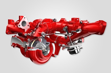
Image Source: www.victor-aviation.com


Understanding Turbochargers

Train engines use turbochargers to increase their power by adding more air to the engine. By compressing the air, more fuel can burn, making the engine work better. (For various turbocharger parts see this page)

Functioning of turbochargers in locomotive engines

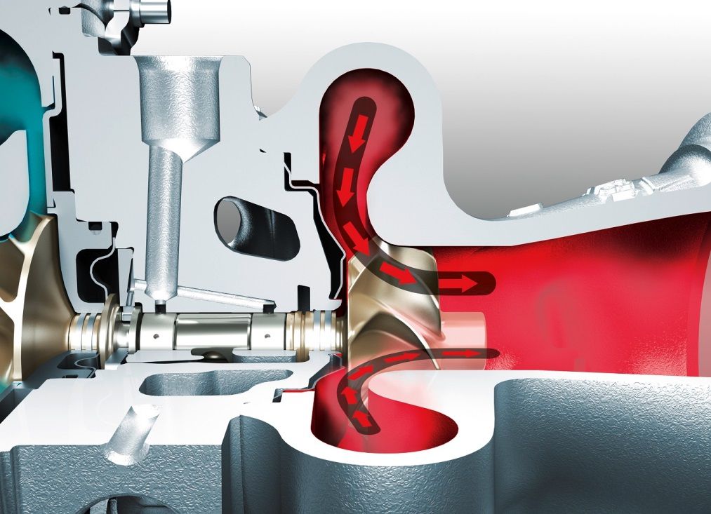
Turbochargers consist of two main components: a turbine and a compressor. The turbine is driven by the engine’s exhaust gases, while the compressor is responsible for compressing the air and directing it into the engine. This compressed air is then mixed with fuel before being ignited in the combustion chamber.

The turbine and compressor are connected by a common shaft, allowing them to work together. As the hot exhaust gases flow through the turbine, they spin the turbine wheel, which, in turn, spins the compressor wheel. The spinning makes the air denser and increases the pressure for more oxygen in the engine.

Factors affecting turbocharger performance

Several factors can affect the performance of a turbocharger in a locomotive engine. Proper maintenance and care are crucial to ensure optimal turbocharger performance. Here are some key factors to consider:

  1. Air inlet casing design: The design of the air inlet casing plays a significant role in turbocharger performance. An efficient design should minimize air restrictions, allowing for smooth and unrestricted airflow into the turbocharger.
  2. Air filter maintenance: Regularly replacing and cleaning the air filter is essential to prevent dust and debris from clogging the turbocharger’s components. A clogged air filter can restrict airflow and decrease performance.
  3. Exhaust gas temperature: High exhaust gas temperatures can put excessive stress on the turbocharger components. Monitoring and controlling exhaust gas temperature through proper tuning and cooling systems is crucial to avoid damage and maintain efficient turbocharger operation.
  4. Regular inspections and maintenance: Periodic inspections and maintenance, including checking for any leaks, worn out parts, or damage, can help identify and rectify any issues before they cause significant damage to the turbocharger.

By understanding the functioning of turbochargers in locomotive engines and considering the factors that affect their performance, operators can enhance turbocharger intake efficiency and ensure optimal engine performance.


Air Inlet Casing: Basics and Benefits

Overview of air inlet casing for locomotive engines

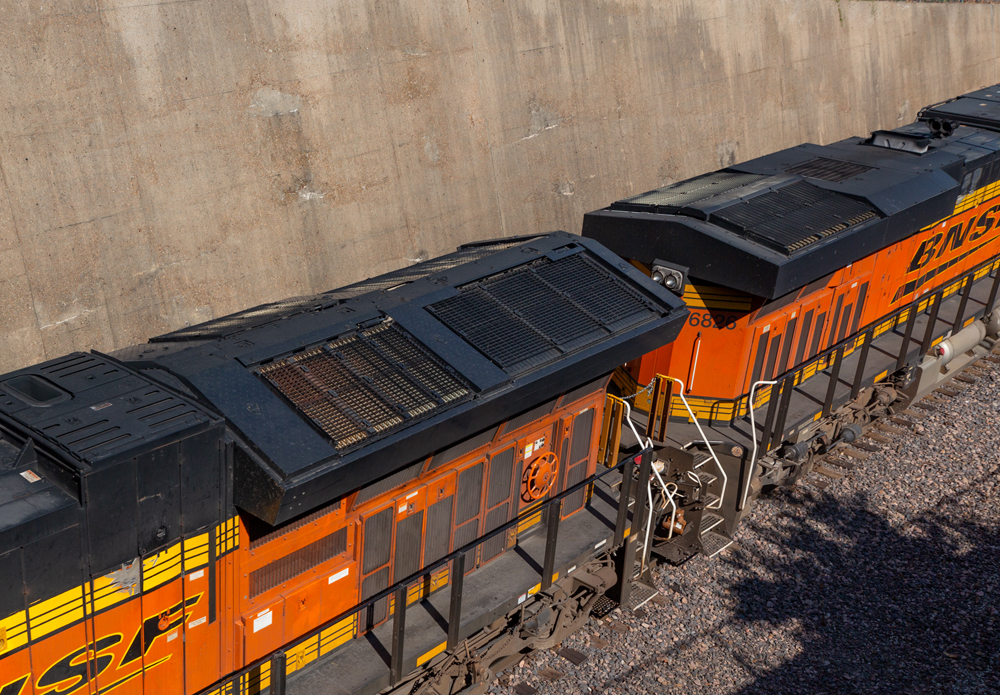
An air inlet casing is a crucial component of locomotive engines, specifically designed to optimize the efficiency of the turbocharger intake system. It serves as a protective enclosure for the turbocharger, which is responsible for compressing and forcing air into the engine’s combustion chambers.

The air inlet casing is typically made of durable materials such as aluminum or steel and is designed to withstand high temperatures, pressures, and vibrations that are commonly found in locomotive engines. It is positioned at the front of the engine, allowing cool and clean air to flow into the turbocharger without any obstructions.

Benefits of using air inlet casing for turbocharger intake efficiency

Using an air inlet casing for turbocharger intake has several benefits for locomotive engines:

  1. Improved air filtration: The air inlet casing acts as an additional layer of protection, preventing dirt, debris, and other contaminants from entering the turbocharger. This helps to prolong the turbocharger’s lifespan and ensures efficient combustion.
  2. Enhanced air flow: The design of the air inlet casing optimizes the airflow into the turbocharger, ensuring a consistent and steady supply of air. This improves the efficiency of the turbocharger, resulting in better engine performance and increased power output.
  3. Noise reduction: The air inlet casing is designed to reduce engine noise caused by turbocharger operation. It helps to minimize sound transmission and dampens compression and exhaust noises, providing a quieter and more comfortable experience for locomotive operators and passengers.
  4. Fuel efficiency: By improving the efficiency of the turbocharger intake system, the air inlet casing aids in maximizing fuel utilization. This can lead to reduced fuel consumption, resulting in significant cost savings for locomotive operators.

In conclusion, using an air inlet casing for train engines has many benefits. It improves air filtration, increases air flow, reduces noise, and boosts fuel efficiency. These benefits help the turbocharger and engine last longer and work better.


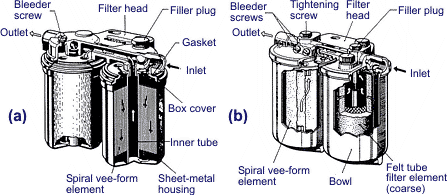
Image Source: dieselnet.com


Design Considerations

Key design considerations for air inlet casing

To make the air inlet casing for train engines efficient, we must consider some important factors.

  1. Airflow: The design should optimize the airflow into the turbocharger. This includes considering the shape, size, and positioning of the air inlet. Smooth and unobstructed airflow is crucial for efficient combustion and power output.
  2. Filtration: The air inlet casing should incorporate a high-quality air filtration system to prevent contaminants from entering the engine. Proper filtration improves the lifespan of the turbocharger and overall engine performance.
  3. Heat management: Efficient heat dissipation is essential to prevent overheating of the turbocharger. The design should include provisions for adequate cooling, such as the use of heat-resistant materials and heat shields.
  4. Noise reduction: The air inlet casing should be designed to minimize noise generated during operation. This can be achieved through the use of sound-dampening materials, optimized airflow paths, and effective mufflers.

Impact of design on turbocharger intake efficiency

The design of the air inlet casing affects how the turbocharger takes in air. This affects how well the locomotive engine performs.

An optimized design can result in:

  • Increased airflow: A well-designed air inlet casing ensures a steady and sufficient airflow into the turbocharger. This improves combustion efficiency, leading to enhanced power output.
  • Improved fuel economy: Efficient turbocharger intake reduces the energy required for the engine to produce power, resulting in better fuel efficiency.
  • Enhanced durability: Proper heat management and filtration reduce the risk of damage to the turbocharger and engine components, extending their lifespan.
  • Reduced maintenance costs: An efficient air inlet casing reduces the likelihood of issues such as clogging and overheating, leading to lower maintenance and repair costs.

In conclusion, it is important to think about design factors. These factors include airflow, filtration, heat management, and noise reduction. They are crucial for making turbocharger intake efficiency better in train engines. Investing in a well-designed air inlet casing can improve performance, fuel efficiency, and durability for operators. This can also lead to lower maintenance costs.


Examples of locomotive engines with air inlet casing
Image Source: dieselnet.com


Case Studies

Examples of locomotive engines with air inlet casing

In the realm of locomotive engines, air inlet casing plays a crucial role in enhancing turbocharger intake efficiency. This innovation has been implemented in various locomotive engines, leading to significant performance improvements. Let’s take a look at some notable examples:

  1. EMD SD70ACe-T4 locomotive: This powerful locomotive model from Electro-Motive Diesel (EMD) features an air inlet casing. The casing is designed to optimize the airflow into the turbocharger, resulting in improved combustion efficiency and reduced emissions.
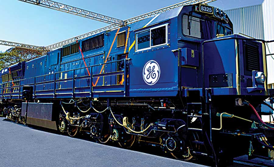
  2. GE Evolution Series locomotive: Another notable locomotive that incorporates an air inlet casing is the GE Evolution Series. This popular locomotive model utilizes the casing to maximize the amount of clean air supply to the turbocharger, enabling better engine performance and fuel efficiency.

Performance improvements achieved with air inlet casing

The implementation of air inlet casing in locomotive engines has yielded several notable performance enhancements. Here are some key improvements achieved:

  1. Increased intake air pressure: The air inlet casing creates a streamlined pathway for the incoming air, ensuring a sufficient and consistent supply to the turbocharger. This results in higher intake air pressure, allowing the engine to generate more power efficiently.
  2. Enhanced fuel combustion: By optimizing the intake air flow, the air inlet casing promotes better fuel combustion within the engine. This leads to improved engine efficiency, reduced fuel consumption, and lower emissions.
  3. Boosted turbocharger performance: The air inlet casing helps the turbocharger operate at its maximum efficiency, delivering more compressed air to the engine cylinders. This results in increased power output and better overall locomotive performance.

In summary, adding an air inlet casing to train engines improves the turbocharger’s ability to take in air. The examples above show how this innovation improves how well trains run. Locomotives that have an air inlet casing can operate more efficiently. To do this, we raise the air pressure, enhance fuel burning, and improve turbocharger performance. This helps them operate more efficiently and get better results.


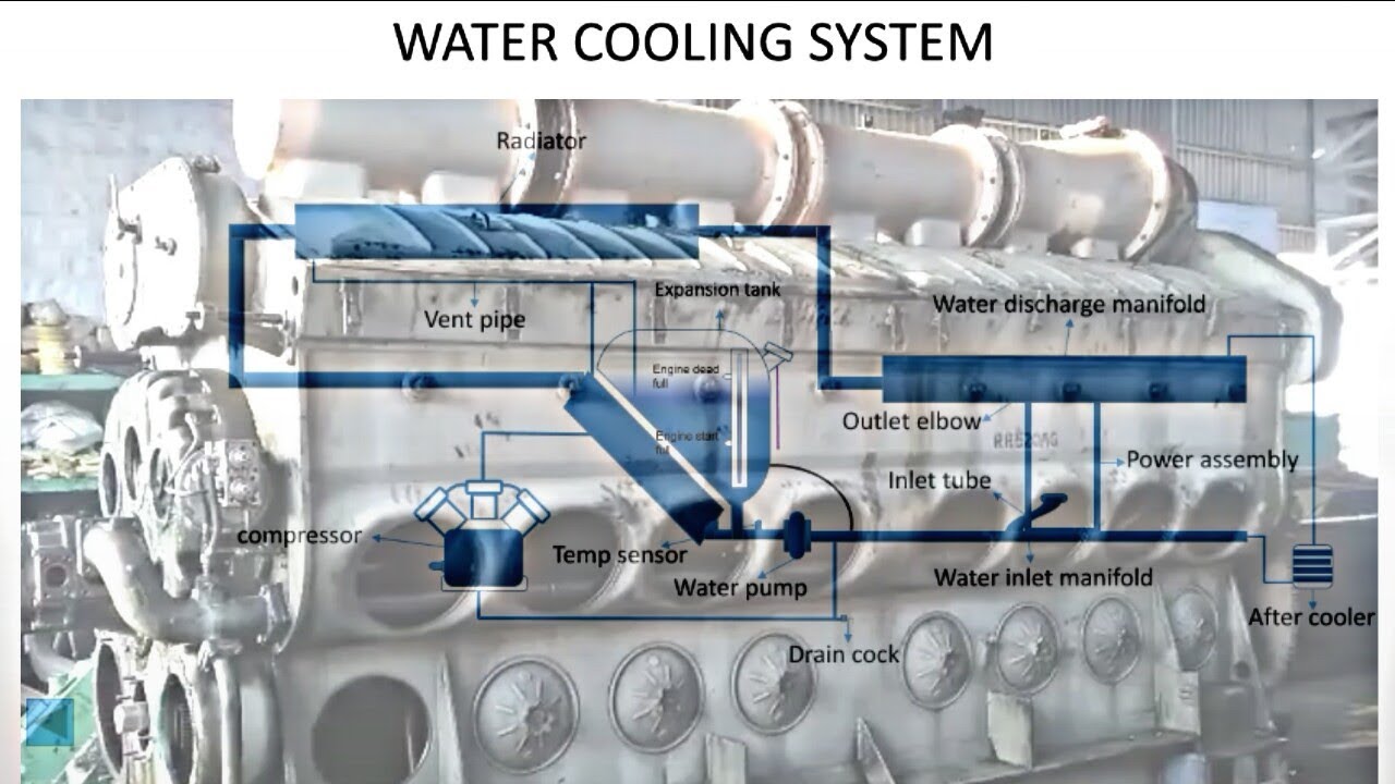
Image Source: i.ytimg.com


Maintenance and Troubleshooting

Maintenance tips for air inlet casing

To keep locomotive engines working well, it’s important to regularly maintain the air inlet casing. This helps them perform better and be more efficient. Here are some essential maintenance tips to keep in mind:

  1. Clean and inspect regularly: Dust, dirt, and debris can accumulate in the air inlet casing, leading to reduced airflow and increased wear and tear on the turbocharger. Regularly clean and inspect the casing to remove any buildup and ensure proper functioning.
  2. Check for leaks: Leaks in the air inlet casing can significantly impact turbocharger intake efficiency. Inspect the casing for any cracks, holes, or loose components that may cause air leakage. Proper sealing and repairs should be done promptly to avoid performance issues.
  3. Inspect the filter: The air filter plays a crucial role in preventing contaminants from entering the engine. Regularly inspect and replace the filter as recommended by the manufacturer to maintain optimal air quality and prevent damage to the turbocharger.

Common issues and troubleshooting techniques

Despite regular maintenance, issues may still arise with the air inlet casing. Here are some common problems and troubleshooting techniques to address them:

  1. Excessive noise: If you notice unusually loud noise coming from the turbocharger or air inlet casing, it could indicate a problem with the casing’s insulation or airflow. Inspect the casing for any loose or damaged components and address the issue accordingly.
  2. Reduced performance: If the locomotive engine is experiencing a decrease in power or efficiency, it could be due to a blocked or clogged air inlet casing. Inspect and clean the casing thoroughly, including the filter, to restore optimal airflow and performance.
  3. Excessive vibration: Excessive vibration can damage the turbocharger and other engine components. Check for any loose or misaligned parts in the air inlet casing and secure or reposition them as necessary.

Use these tips and techniques to keep the air inlet casing in good condition. This will make the turbocharger work better and the engine perform better overall.


Future Developments

Potential advancements in air inlet casing technology

In the field of locomotive engine design, there is a continuous drive for innovation and improvement. One area that holds promise for enhancing turbocharger intake efficiency is the development of air inlet casing technology. Here are some potential advancements to look out for:

  1. Increased aerodynamic design: Engineers are exploring ways to refine the shape and design of air inlet casings to optimize airflow. By reducing turbulence and improving airflow distribution, these advancements aim to enhance the overall efficiency of the turbocharging system.
  2. Improved filtration systems: As air quality becomes increasingly important, manufacturers are working on more advanced filtration systems integrated into the air inlet casings. These systems will help trap harmful particles and contaminants, ensuring cleaner air enters the engine, which can improve both performance and longevity.
  3. Intelligent control systems: The integration of smart sensors and control systems within air inlet casings is another area of potential advancement. These systems can monitor and adjust airflow and pressure in real-time, optimizing performance based on various operating conditions and environmental factors.

Anticipated benefits for locomotive engine performance

The new technology for train engine air inlet casing will make them work better and use less energy. Some anticipated advantages include:

  1. Increased power output: By optimizing airflow into the turbocharger, the engine can benefit from improved combustion efficiency and increased power output.
  2. Enhanced fuel efficiency: With a more efficient turbocharger intake system, the engine can achieve better fuel economy, reducing operating costs and environmental impact.
  3. Extended engine lifespan: The integration of advanced filtration systems can help protect the engine components from premature wear caused by contaminant ingestion. This would result in longer intervals between maintenance and reduced downtime.
  4. Improved reliability: The use of intelligent control systems can ensure optimal performance under different operating conditions, reducing the chances of engine malfunction and enhancing overall reliability.

As we keep researching, the technology for train engine air inlet casing will get better. This will make the engines more efficient and reliable. This will benefit operators and the environment.


Image Source: dieselnet.com


Conclusion

In conclusion, the air inlet casing is very important for locomotive engines. It helps the turbocharger work better. To make engines work better, we can improve air filtration, reduce pressure drop, and increase air density.

Summary of the importance of air inlet casing for enhancing turbocharger intake efficiency

The air inlet casing keeps the turbocharger safe from harmful things in the air. To reduce pressure drop, optimize the airflow path. Make sure the turbocharger gets steady and uninterrupted air. The air inlet casing improves the turbocharger. It saves energy and increases air compression. The casing design can include air straighteners and diffusers. These features improve air intake efficiency by making airflow smooth and even.

Promising future prospects for air inlet casing implementation in locomotive engines

As locomotive engines continue to evolve and become more advanced, the implementation of air inlet casing is expected to become even more prevalent. With increasing environmental regulations and the need for improved fuel efficiency, the role of turbocharged engines is becoming more prominent. The air inlet casing offers an effective solution for enhancing turbocharger intake efficiency and addressing these challenges. Furthermore, advancements in material technology and aerodynamic design techniques are enabling the development of more efficient and robust air inlet casing designs. This, in turn, will lead to improved overall engine performance, reduced emissions, and greater fuel efficiency, making air inlet casing an essential component in locomotive engines of the future.


Q: What is the purpose of the Air Inlet Casing for Locomotive Engines?

A: The Air Inlet Casing is designed to enhance the intake efficiency of the turbocharger in locomotive engines. The Air Inlet Casing is an important component in locomotive engines as it is specifically designed to optimize the intake efficiency of the turbocharger. The turbocharger plays a crucial role in improving the performance of the engine by increasing the intake air pressure and density, which results in enhanced combustion and power output.

The Air Inlet Casing is typically installed between the air cleaner and the turbocharger compressor inlet. Its primary function is to create a smooth and streamlined path for the incoming air to flow into the turbocharger. The design of the casing is crucial to reduce air flow losses, minimize turbulence, and maximize the efficiency of the turbocharger.
One of the key features of the Air Inlet Casing is its shape and internal design. It is typically designed to have a gradual and continuous taper from the air cleaner inlet to the turbocharger compressor inlet. This tapering design helps to reduce any abrupt changes in the air flow, promoting better air distribution and minimizing pressure losses.

Furthermore, the Air Inlet Casing may also incorporate additional features such as air straighteners or diffusers. These components help to further optimize the airflow by straightening out any swirl or turbulence in the incoming air. By ensuring a smooth and controlled flow of air into the turbocharger, the efficiency of the turbocharger is maximized, resulting in improved engine performance.

Overall, the Air Inlet Casing is a crucial component in locomotive engines, as it plays a vital role in enhancing the intake efficiency of the turbocharger. By optimizing the airflow and minimizing any losses or turbulence, the casing helps to maximize the power output and efficiency of the engine, resulting in improved locomotive performance.

Q: What role does the turbocharger play in the engine?

A: The turbocharger is a machine that uses a gas turbine to compress the intake air, thus increasing the engine’s power output. A turbocharger consists of two key components: a turbine and a compressor, connected by a central shaft. The turbine is usually driven by the exhaust gases produced by the engine, while the compressor is responsible for increasing the air pressure and density that goes into the engine.

When the engine’s exhaust gases flow through the turbine, they cause it to spin rapidly. This spinning motion transfers power to the compressor, which in turn compresses the intake air. By compressing the air, the turbocharger increases the amount of oxygen available for combustion inside the engine cylinders.

With more oxygen available, more fuel can be added to the combustion process, resulting in improved power output. This process is known as forced induction, as the air is being forced into the engine at a higher pressure than atmospheric conditions would allow.

The compressed air from the turbocharger is then directed into the engine’s intake manifold, where it mixes with fuel before entering the combustion chambers. The result is a more efficient and powerful combustion process, leading to increased engine performance.

Turbochargers are commonly used in automotive applications, especially in high-performance and sports cars, as well as in diesel engines. They provide a significant boost in power without the need for a larger or heavier engine.
However, turbochargers also have some drawbacks. They can generate heat and increase the strain on the engine, which requires additional cooling mechanisms and reinforced engine components. Turbolasers can also create a slight delay in power delivery, known as turbo lag, before the turbocharger spools up to its full operating speed.

Overall, turbochargers are a popular technology for enhancing the power output of internal combustion engines, providing increased efficiency and performance while maintaining relatively compact engine sizes.


Q: What is the role of the air inlet casing in enhancing turbocharger intake efficiency?

A: The air inlet casing is designed to optimize the flow of air into the turbocharger, reducing turbulence and pressure losses, thus improving the overall efficiency of the turbocharger. By minimizing turbulence and pressure losses, the air inlet casing allows for a smoother and more even flow of air into the turbocharger. This optimizes the performance of the turbocharger by ensuring that the maximum amount of air can be compressed and delivered to the engine.

The design of the air inlet casing typically includes features such as streamlined contours and smooth internal surfaces. These features help to reduce air turbulence, which can create resistance and cause pressure losses. By minimizing turbulence, the air can flow more freely and efficiently into the turbocharger, allowing for maximum compression.
In addition to reducing turbulence, the air inlet casing also helps to prevent the ingress of debris and foreign objects into the turbocharger. This is important as even small particles can cause damage to the delicate components of the turbocharger, leading to reduced efficiency and potential breakdown.

Overall, the design of the air inlet casing plays a crucial role in optimizing the performance and efficiency of the turbocharger. By reducing turbulence and pressure losses, it allows for a smoother flow of air into the turbocharger, maximizing its ability to compress and deliver air to the engine. This ultimately leads to improved engine performance and fuel efficiency.

Q: How does the air inlet casing achieve better flow and reduced turbulence?

A: The air inlet casing features advanced designs, such as optimized ducting and plenum chambers, to guide the air smoothly into the turbocharger, minimizing turbulence and improving airflow. This results in greater efficiency and performance of the turbocharger, as the smooth airflow allows for quicker spooling and increased air volume, which in turn enhances engine power and torque.

The optimized ducting ensures that the air is directed precisely towards the turbine wheel, eliminating any unnecessary air resistance or blockages. This ensures maximum utilization of the turbocharger’s potential and reduces energy loss.
Furthermore, the plenum chambers play a crucial role in maintaining a constant and steady flow of air into the turbocharger. These chambers act as reservoirs, storing pressurized air and releasing it when needed. This ensures a constant supply of air to the turbocharger, minimizing any disruptions in airflow and enabling consistent performance.

By incorporating advanced designs such as optimized ducting and plenum chambers, the air inlet casing effectively minimizes turbulence and maximizes airflow, resulting in improved turbocharger efficiency and overall engine performance.

Q: Is the air inlet casing compatible with different types of locomotive engines?

A: Yes, the air inlet casing is designed to be adaptable and can be customized to suit various locomotive engines, making it compatible with a wide range of applications. The air inlet casing is designed with the flexibility to accommodate different locomotive engines. It can be customized to fit the specific requirements of various applications. This adaptability ensures that the air inlet casing can be used with a wide range of locomotive engines, making it compatible with different models and configurations.

Q: Do you offer a complete kit for the installation of the air inlet casing?

A: Yes, we at Mikura International provide a comprehensive kit that includes all the necessary components for the installation of the air inlet casing, ensuring a hassle-free setup process. Our kit includes the air inlet casing, mounting brackets, screws, and any additional accessories required for installation. We understand the importance of a smooth setup process, and our comprehensive kit eliminates the need for customers to source separate components, saving them time and effort.

At Mikura International, we prioritize customer satisfaction and strive to provide high-quality products and services.

Understanding ALCO Fuel Pump Parts

Understanding ALCO Fuel Pump Parts

ALCO Fuel Pump

Introduction:

ALCO fuel pumps play a crucial role in the efficient functioning of diesel engines. As a trusted brand in the industry, ALCO is recognized for its quality and value in providing fuel pump solutions for a wide range of applications. ALCO fuel pumps are known for their durability, performance, and reliability, making them a popular choice among customers. In this article, we will dive deeper into understanding the different parts of an ALCO fuel pump and their significance in the overall functioning of the engine. By gaining a better understanding of these essential components, users can enhance their knowledge of fuel pump operations and make informed decisions when it comes to fuel pump maintenance and replacement.

What is an ALCO Fuel Pump?

An ALCO Fuel Pump is an essential component of an ALCO locomotive engine that plays a crucial role in delivering fuel for combustion. Its main purpose is to ensure a steady and consistent flow of fuel to the engine, helping to maintain optimal performance and efficiency.

The ALCO Fuel Pump functions by drawing fuel from the fuel tank and delivering it to the engine’s fuel injectors. It operates through a series of mechanical processes that rely on the engine’s rotation and pressure changes to pump the fuel.

Key components of an ALCO Fuel Pump include the fuel pump housing, plunger, delivery valve, and camshaft. The fuel pump housing houses all the necessary parts and provides a secure and sealed environment for fuel delivery. The plunger is responsible for creating the necessary pressure to move the fuel through the pump system. The delivery valve controls the flow of fuel into the engine’s fuel injectors, ensuring precise and accurate fuel delivery. The camshaft, driven by the engine’s rotation, helps synchronize the movement of the plunger and delivery valve.

In summary, an ALCO Fuel Pump is vital for the proper functioning of an ALCO locomotive engine. It ensures a consistent and precise flow of fuel to the engine, optimizing performance and efficiency. By understanding its components and the fuel delivery process, maintenance issues can be addressed, leading to improved longevity and reliability of the fuel pump.

How does an ALCO Fuel Pump work?

The ALCO Fuel Pump operates through a series of mechanical processes to deliver fuel from the fuel tank to the engine’s fuel injectors. It plays a crucial role in ensuring that the engine receives the necessary amount of fuel for proper combustion.

At the heart of the ALCO Fuel Pump are key components that work together seamlessly. The fuel pump housing provides a secure and sealed environment for fuel delivery. It houses the various parts like the plunger, delivery valve, and camshaft.

The plunger is responsible for creating the required pressure to move the fuel through the pump system. It moves up and down within the pump housing, drawing fuel in and pushing it out to the engine.

The delivery valve controls the flow of fuel into the engine’s fuel injectors, ensuring precise and accurate fuel delivery. It opens and closes at the right time to regulate the amount of fuel entering the combustion chamber.

The camshaft, driven by the engine’s rotation, acts as a synchronizer, coordinating the movement of the plunger and delivery valve. It ensures the right timing of fuel injection into the engine.

Understanding how an ALCO Fuel Pump works is crucial for fuel injection pump reconditioning. This process involves disassembling the pump, thoroughly cleaning all components, inspecting for any damage or wear, lapping the parts if necessary, pressure testing to ensure proper function, and calibrating to meet the engine’s requirements.

In conclusion, the ALCO Fuel Pump is a vital component in the fuel delivery system of an engine. Its key components work together to ensure proper fuel supply, and understanding its operation is essential for maintenance and reconditioning.

Where can you buy ALCO Fuel Pumps?

You can buy ALCO Fuel Pumps from reliable suppliers like Mikura International. As a leading supplier of ALCO locomotive parts, Mikura International is committed to providing high-quality products and excellent customer service.

Mikura International understands the importance of quality when it comes to fuel pumps. That’s why they offer a wide range of ALCO Fuel Pumps that are manufactured to meet the highest standards. Whether you need a fuel pump for a conventional high-power diesel engine or a 2-stroke reciprocating piston engine, Mikura International has you covered.

Not only does Mikura International offer a wide selection of ALCO Fuel Pumps, but they also provide outstanding customer service. Their team of experts is always ready to assist you with any questions or concerns you may have. They are committed to ensuring customer satisfaction and will go above and beyond to meet your needs.

When it comes to purchasing ALCO Fuel Pumps, trust Mikura International as your reliable supplier. With their commitment to quality products and excellent customer service, you can be confident that you are getting the best fuel pumps for your locomotive engine.

What are the different types of ALCO Fuel Pumps?

ALCO Fuel Pumps are available in a variety of types to suit different engines and applications. Here are some of the different types:

1. Mechanical Fuel Pumps: These fuel pumps use mechanical action to deliver fuel to the engine. They are commonly used in older engines and offer simplicity and reliability.

2. Fuel Injection Pump: ALCO Fuel Injection Pumps are designed to deliver fuel with precision and efficiency. They undergo a reconditioning process to ensure optimal performance.

3. Parts Inspection: ALCO Fuel Pump parts undergo thorough inspection to ensure top-notch quality. This includes checking for any defects or wear and tear that could affect performance.

4. Delivery Valves: ALCO Fuel Pumps also feature delivery valves, which control the flow of fuel to the engine. These valves are crucial for efficient fuel delivery and are meticulously designed and manufactured.

ALCO Fuel Pumps, including their different types, are manufactured to meet the highest quality standards. Mikura International, a trusted provider, offers a wide range of ALCO Fuel Pumps to cater to various engine types and applications. Their dedicated team of experts provides outstanding customer service, ensuring customer satisfaction. Whether you need a fuel pump for a conventional high-power diesel engine or a 2-stroke reciprocating piston engine, Mikura International has the right ALCO Fuel Pump for you.

How to replace an ALCO Fuel Pump?

Replacing an ALCO Fuel Pump can be done by following a step-by-step process. Here’s a guide on how to do it:

1. Preparation: Start by ensuring that you have all the necessary tools and replacement parts for the job. This may include a wrench, socket set, new ALCO Fuel Pump, gasket, and sealant. Make sure the engine is turned off and the fuel supply is disconnected.

2. Removal: Locate the existing fuel pump on your engine. It is typically attached to the engine block or cylinder head. Begin by removing any mounting bolts or clips securing the pump in place. Carefully disconnect the fuel lines attached to the pump, ensuring that no fuel spills occur. Remove any electrical connections if applicable.

3. Installation: Clean the mounting surface thoroughly to ensure a proper seal. Position the new ALCO Fuel Pump in place, aligning it with the mounting holes. Use the correct gasket and apply a thin layer of sealant on both sides. Carefully reconnect the fuel lines, making sure they are securely tightened. Reattach any electrical connections if required.

4. Testing: Once the new pump is installed, turn on the engine and check for any fuel leaks. Make sure the fuel pump is delivering fuel to the engine properly. Run the engine for a few minutes to ensure everything is functioning correctly.

By following these steps, you can successfully replace an ALCO Fuel Pump and ensure optimal performance and fuel delivery to your engine.

Components of an ALCO Fuel Pump

An ALCO fuel pump is a crucial component in the fuel delivery system of an engine. It is responsible for drawing fuel from the tank and delivering it to the engine at the correct pressure and flow rate. Understanding the various components of an ALCO fuel pump can help in troubleshooting and maintaining its optimal performance.

1. Electric or Mechanical Operation: ALCO fuel pumps can be either electrically or mechanically operated. Electric fuel pumps are powered by the electrical system of the vehicle and are commonly found in modern vehicles. Mechanical fuel pumps, on the other hand, are driven by the engine’s camshaft or crankshaft and are typically found in older vehicles.

2. Pump Body: The pump body is the main housing of the fuel pump. It houses the internal components and provides a secure enclosure for the pump.

3. Inlet and Outlet Ports: The fuel pump has an inlet port, where fuel is drawn from the fuel tank, and an outlet port, where the fuel is delivered to the engine. These ports are connected to the fuel lines through fittings or connectors.

4. Fuel Filter: Many ALCO fuel pumps come with an integrated fuel filter. This filter removes any contaminants or debris from the fuel before it enters the pump. Keeping the filter clean is essential for the pump’s longevity and preventing fuel system issues.

5. Pressure Relief Valve: The pressure relief valve is a safety feature that regulates the fuel pressure within the pump. It opens when the pressure exceeds a specific limit, preventing damage to the pump and the rest of the fuel system.

6. Check Valve: The check valve ensures a one-way flow of fuel from the pump to the engine. It prevents fuel from flowing backward and maintains proper fuel pressure when the engine is not running.

By familiarizing yourself with these components, you can better understand how an ALCO fuel pump works and perform maintenance or troubleshooting tasks as needed. Regular maintenance, including replacing filters and inspecting for leaks, is crucial to keep the fuel pump functioning optimally and ensure uninterrupted fuel delivery to the engine.

Electric motor

The electric motor in an ALCO fuel pump plays a crucial role in its operation and overall performance. Its main function is to power the pump, enabling efficient and reliable fuel delivery to the engine.

The electric motor powers the pump by converting electrical energy into mechanical energy. It drives the pump’s internal components, which draw fuel from the tank and deliver it to the engine at the correct pressure and flow rate. This ensures that the engine receives the required amount of fuel for optimal combustion and performance.

Efficient fuel delivery is essential for the smooth operation of an engine. The electric motor in the ALCO fuel pump ensures consistent and reliable fuel flow, preventing fuel starvation or flooding issues. This not only helps in maintaining the engine’s performance but also improves fuel efficiency.

When choosing an electric motor, it is important to consider its power rating, voltage requirements, and motor type. The power rating indicates the motor’s capability to provide sufficient power for the fuel pump. Voltage requirements specify the electrical input that the motor needs to function properly. Additionally, the motor type, such as brushless or brushed, impacts the motor’s efficiency and durability.

Overall, the electric motor in an ALCO fuel pump is an essential component that enables efficient fuel delivery, ensuring the engine operates at its optimum performance level.

Fuel reservoir

The fuel reservoir in an ALCO Fuel Pump plays a vital role in the efficient operation of the pump. Its primary function is to store and supply fuel to the pump for continuous and uninterrupted fuel delivery to the engine.

As the pump draws fuel from the tank, it is stored in the fuel reservoir. This reservoir acts as a buffer, ensuring a steady supply of fuel to the pump. This is particularly important in situations where fuel consumption may fluctuate, or when the engine demands more fuel under heavy load conditions.

The fuel reservoir also helps in filtering out any impurities or debris present in the fuel. It typically employs a filtration system that prevents contaminants from entering the pump and ultimately reaching the engine. This ensures the smooth and reliable operation of the entire fuel system.

Proper maintenance and regular cleaning of the fuel reservoir are crucial for optimal pump performance. Over time, debris and sediment can accumulate in the reservoir, potentially clogging the fuel lines or causing damage to the pump. Regular inspection and cleaning of the reservoir help prevent these issues, ensuring a clean fuel supply and maximizing the lifespan of the fuel pump.

In conclusion, the fuel reservoir in an ALCO Fuel Pump serves as a storage and filtration system that supplies clean fuel to the pump. Regular maintenance and cleaning of the reservoir are essential to keep the fuel system running smoothly and the pump operating at its best.

Inlet and outlet ports

The design and function of the inlet and outlet ports are crucial components of an ALCO Fuel Pump. These ports serve the purpose of allowing the smooth flow of fuel within the pump, ensuring optimal performance and fuel delivery to the engine.

The inlet port is responsible for drawing fuel from the fuel reservoir or tank into the pump. It is designed to create a vacuum or negative pressure that pulls the fuel into the pump. This pull is facilitated by the pump’s internal mechanisms, such as pistons or diaphragms, which operate in sync with the engine’s cycles.

On the other hand, the outlet port is responsible for expelling the pressurized fuel from the pump and delivering it to the engine. It is designed to withstand high pressure, ensuring that fuel flows efficiently to the engine’s combustion chambers.

ALCO Fuel Pumps commonly utilize different types of inlet and outlet ports, depending on the specific application and design requirements. Some common types include threaded ports, flanged ports, barbed ports, and quick-connect ports. Each type of port offers its own advantages in terms of ease of installation, connection reliability, and resistance to leaks.

Understanding the design and function of the inlet and outlet ports is essential in maintaining and optimizing the performance of an ALCO Fuel Pump. Proper care and regular inspection of these ports are important to ensure an uninterrupted fuel flow and extend the lifespan of the pump.

Symptoms of a faulty ALCO Fuel Pump

A faulty ALCO Fuel Pump can cause various issues in the fuel delivery system, ultimately affecting the performance of your engine. It is important to recognize the symptoms of a faulty fuel pump in order to address the problem before it leads to more serious damage. One common symptom is engine misfires or hesitation during acceleration, as the inadequate fuel supply disrupts the combustion process. Another indication of a faulty fuel pump is a loss of power, as the engine does not receive enough fuel to operate at its full potential. Additionally, sputtering or stalling of the engine, especially at high speeds, can signal a fuel pump issue. If you notice any of these symptoms, it is crucial to have your ALCO Fuel Pump inspected and potentially replaced to ensure optimal engine performance and prevent further damage.

Engine misfires

Engine misfires can occur due to various reasons, causing a loss of power, rough idling, and increased emissions. Here are some possible causes of engine misfires:

1. Faulty spark plugs: Worn or damaged spark plugs can result in weak or no spark, leading to misfires. Regular inspection and replacement of spark plugs can prevent this issue.

2. Ignition coil or distributor problems: Malfunctioning ignition coils or distributors can cause inconsistent firing of spark plugs, resulting in misfires. These components should be inspected and replaced if necessary.

3. Fuel injector issues: Clogged or faulty fuel injectors can disrupt the fuel distribution to the engine cylinders, leading to misfires. Cleaning or replacing the fuel injectors can resolve this issue.

4. Vacuum leak: A vacuum leak in the intake manifold can cause an imbalance in the air-fuel mixture, resulting in misfires. Checking and repairing any vacuum leaks can rectify this problem.

5. Faulty sensors: Issues with sensors such as the mass airflow sensor (MAF) or oxygen sensor (O2) can cause incorrect fuel delivery, leading to misfires. Replacing or calibrating these sensors can help resolve the problem.

6. Low fuel pressure: A weak fuel pump or restricted fuel filter can result in insufficient fuel supply to the engine, causing misfires. Checking and replacing the fuel pump or filter can address this issue.

7. Engine timing problems: Incorrect ignition timing or valve timing can lead to misfires. Proper adjustment or repair of timing components can fix this issue.

Troubleshooting engine misfires requires diagnosing and addressing these possible causes. Regular maintenance and timely repairs can help prevent misfires and ensure smooth engine operation.

Loss of power

Loss of power in an ALCO Fuel Pump can be caused by various factors. One common cause is a clogged or dirty fuel filter. Over time, the fuel filter can become blocked with debris, restricting the flow of fuel to the engine, resulting in a loss of power. Regularly replacing the fuel filter can help prevent this issue.

Another possible cause of power loss is a faulty fuel pump. A worn or malfunctioning fuel pump may not be able to deliver the necessary amount of fuel to the engine, leading to a decrease in power. In such cases, replacing the ALCO Fuel Pump with a brand-new one is often the solution.

Additionally, a fuel injection system that is not properly calibrated can also lead to a loss of power. This can be rectified by ensuring that the fuel injectors are clean and functioning correctly. Replacing any faulty or clogged injectors can help restore power.

Lastly, a failing or weak spark plug can result in misfires and a decrease in engine performance. Inspecting and replacing spark plugs regularly can help prevent power loss.

If you’re experiencing a loss of power in your ALCO Fuel Pump, it’s important to troubleshoot the problem and address it promptly. By checking and repairing potential causes such as clogged fuel filters, faulty fuel pumps, improper fuel injection calibration, and worn spark plugs, you can restore the power and efficiency of your ALCO Fuel Pump.

Difficulty starting the engine

Difficulty starting the engine can be a frustrating issue that may indicate a problem with the ALCO Fuel Pump. To address this issue, there are several steps you can take:

1. Check the fuel filter: A clogged fuel filter can restrict the fuel flow to the engine, making it difficult to start. Inspect the fuel filter and replace it if necessary.

2. Test the fuel pump pressure: A weak fuel pump may not deliver enough fuel to the engine, resulting in difficulty starting. Use a fuel pressure gauge to measure the pressure and ensure it meets the manufacturer’s specifications. If the pressure is low, consider replacing the fuel pump.

3. Inspect for fuel leaks: Fuel leaks can cause air to enter the fuel system, which can make starting the engine difficult. Inspect the fuel lines, connections, and the fuel pump itself for any signs of leaks. If any leaks are found, they should be repaired immediately.

4. Check the electrical connections: Faulty electrical connections to the fuel pump can also lead to difficulty starting the engine. Ensure that all electrical connections are secure and free from corrosion.

By following these troubleshooting methods and addressing any issues with the clogged fuel filter, weak fuel pump, or fuel leaks, you can help resolve the difficulty starting the engine with the ALCO Fuel Pump.

ALCO Fuel Pump installation

Introduction:

Installing an ALCO fuel pump is a crucial step in ensuring the proper functioning of your engine. Whether you are replacing a faulty fuel pump or installing a new one, it is important to follow the correct installation process to prevent any issues or damage to your engine. In this article, we will provide you with a step-by-step guide on how to install an ALCO fuel pump, along with some important tips to keep in mind during the installation process. By following these instructions, you can ensure that your ALCO fuel pump is installed correctly, allowing for efficient fuel delivery and optimal engine performance.

1. Gather the necessary tools and equipment:

Before starting the installation, make sure you have all the necessary tools and equipment on hand. This may include a socket wrench set, pliers, screwdrivers, and a fuel pump installation kit, which typically includes gaskets, seals, and other necessary components.

2. Disconnect the battery:

To prevent any accidental electrical sparks or damage, disconnect the battery by removing the negative terminal connection.

3. Locate the fuel pump:

Next, locate the current fuel pump or the installation point for the new pump. The fuel pump is usually located near the fuel tank, either inside or outside of it, depending on the vehicle model. Refer to your vehicle’s manual for specific instructions.

4. Remove the old fuel pump (if applicable):

If you are replacing an existing fuel pump, carefully remove it by disconnecting the fuel lines, electrical connections, and any mounting bolts. Take note of the connections and their order for easy installation of the new pump.

5. Install the new ALCO fuel pump:

Using the provided gaskets and seals, install the new ALCO fuel pump in the same location as the old one. Ensure that the pump’s inlet and outlet connections align with the fuel lines. Tighten any mounting bolts according to the manufacturer’s specifications.

6. Reconnect the fuel lines and electrical connections:

Reconnect the fuel lines and electrical connections to the new ALCO fuel pump, ensuring they are securely attached. Double-check and tighten any connections if necessary.

7. Reconnect the battery:

After the installation is complete, reconnect the battery by attaching the negative terminal connection.

8. Test the fuel pump:

Before starting the engine, conduct a fuel pump test to ensure proper installation. Turn the ignition to the ON position without starting the engine and listen for the fuel pump to prime. Check for any fuel leaks and verify that the pump is operating smoothly.

9. Start the engine:

Once you have confirmed the proper installation and functioning of the fuel pump, start the engine and check for any abnormal noises or issues.

By following these steps, you can successfully install an ALCO fuel pump, ensuring reliable fuel delivery and optimal engine performance. If you encounter any difficulties or are unsure about any step, it is always advisable to consult a professional mechanic.

Preparation steps

Before replacing an ALCO Fuel Pump, it is important to follow a few necessary preparation steps to ensure a smooth installation process.

The first step is to inspect the current fuel pump to determine if it needs to be replaced. Look for any signs of damage or malfunction, such as leaks, clogs, or unusual noises. If the fuel pump is not working properly, it is time for a replacement.

Next, gather the required tools and equipment for the installation. This may include a socket wrench set, pliers, screwdrivers, and a fuel pump installation kit. The installation kit typically includes gaskets, seals, and other necessary components for a successful installation. Having all the necessary tools and equipment on hand will make the installation process much easier and efficient.

Lastly, make sure you have a replacement pump available. It is essential to have the correct ALCO Fuel Pump model to ensure compatibility and optimal performance. Check your vehicle’s manual or consult with a professional to determine the appropriate ALCO Fuel Pump model for your engine.

By following these preparation steps, you can ensure a successful and hassle-free replacement of your ALCO Fuel Pump.

Removal of old pump

When it comes to removing an old ALCO Fuel Pump, there are a few important steps to follow. First, it is crucial to inspect the pump for any signs of damage or wear. Look for leaks, clogs, or unusual noises that may indicate a malfunctioning pump. If the pump is not functioning properly, it is time for a replacement.

Once the pump has been inspected and deemed in need of replacement, gather the necessary tools and equipment for the removal process. This usually includes a socket wrench set, pliers, screwdrivers, and a fuel pump removal kit. The removal kit typically contains gaskets, seals, and other components needed for a successful removal.

Having all the required tools and equipment at hand will ensure a smooth and efficient removal process. This will save both time and effort. It is also crucial to have a replacement pump available that is compatible with your engine. Take reference from your vehicle’s manual or consult a professional to determine the correct ALCO Fuel Pump model needed for optimal performance.

By following these steps and using the appropriate tools and equipment, you can efficiently and effectively remove an old ALCO Fuel Pump and replace it with a new one, ensuring your engine runs smoothly and efficiently.

Installation of new pump

Installing a new ALCO Fuel Pump can be done by following a step-by-step process. Here are the necessary preparation steps, removal of the old pump, and installation of the new pump:

1. Preparation Steps:

– Before starting the installation process, make sure you have the necessary tools and equipment at hand, including a socket wrench set, pliers, screwdrivers, and a new ALCO Fuel Pump.

– Ensure that the engine is turned off and the vehicle is parked in a safe and stable location.

– Familiarize yourself with the layout of the old pump and take reference from your vehicle’s manual or consult a professional to determine the correct ALCO Fuel Pump model needed for optimal performance.

2. Removal of the Old Pump:

– Begin by disconnecting the negative terminal of the vehicle’s battery to prevent any accidental electrical discharges.

– Locate the old fuel pump, which is typically mounted near the fuel tank or engine compartment.

– Disconnect any electrical connectors or hoses attached to the pump.

– Use the appropriate tools to remove the mounting bolts securing the pump in place.

– Carefully remove the old pump from its position, taking note of any gaskets or seals that might need replacement.

3. Installation of the New Pump:

– Compare the new ALCO Fuel Pump with the old pump to ensure they are identical.

– Replace any gaskets or seals as needed.

– Carefully position the new pump in place and secure it with the mounting bolts.

– Reconnect any electrical connectors or hoses to the appropriate ports on the new pump.

– Double-check all connections and ensure they are secure.

– Reconnect the negative terminal of the vehicle’s battery.

By following these steps, you can successfully install a new ALCO Fuel Pump. Remember to refer to your vehicle’s manual or seek professional assistance if needed.

How to troubleshoot ALCO Fuel Pump issues?

Introduction:

The ALCO Fuel Pump is an essential component of a vehicle’s fuel system, responsible for delivering fuel from the tank to the engine. Like any mechanical part, the fuel pump can experience issues over time. Troubleshooting these issues is crucial for maintaining optimal vehicle performance. In this guide, we will walk you through the steps to troubleshoot common ALCO Fuel Pump problems, helping you identify the cause of the issue and take appropriate action. By understanding how to troubleshoot ALCO Fuel Pump issues, you can save time and money by diagnosing and resolving problems on your own.

1. Check for Fuel Flow Issues:

If your vehicle is experiencing a lack of fuel or intermittent fuel supply, it could be due to issues with the ALCO Fuel Pump. Start by inspecting the fuel lines for any leaks, blockages, or damage. Ensure that the fuel filter is clean and not clogged. You can also perform a fuel pressure test using a pressure gauge to determine if the fuel pump is delivering the correct pressure to the engine. If the fuel flow is insufficient or inconsistent, it may indicate a faulty ALCO Fuel Pump that needs to be replaced.

2. Test for Electrical Problems:

Faulty electrical connections or a malfunctioning fuel pump relay can also cause issues with the ALCO Fuel Pump. Use a multimeter to check the fuel pump’s electrical connections for proper voltage and continuity. Inspect the wiring harness for any signs of damage, corrosion, or loose connections. If the electrical tests reveal any faults, repair or replace the affected components to ensure proper operation of the fuel pump.

3. Inspect the Fuel Pump Module:

In some vehicles, the ALCO Fuel Pump is integrated into a module, which also includes the fuel level sender and other components. If you suspect an issue with the fuel pump module, you will need to remove it from the fuel tank for inspection. Check for signs of damage, corrosion, or contamination. In case of any visible issues, it is recommended to replace the entire fuel pump module to ensure the longevity and reliability of the fuel system.

4. Seek Professional Assistance:

If you have performed the troubleshooting steps mentioned above and are still experiencing issues with the ALCO Fuel Pump, it may be best to consult a professional mechanic or a fuel system specialist. They have the expertise and diagnostic tools necessary to accurately identify and resolve complex fuel pump problems. It is important to address fuel system issues promptly, as a malfunctioning fuel pump can lead to engine performance issues, increased fuel consumption, and potential damage to other components of the fuel system.

In conclusion, troubleshooting ALCO Fuel Pump issues requires a systematic approach to identify and resolve potential problems. By following the steps outlined in this guide, you can diagnose common fuel pump issues and take appropriate action. Remember, regular inspection, maintenance, and prompt repairs are essential for ensuring the longevity and optimal performance of your ALCO Fuel Pump and the overall fuel system of your vehicle.

Common problems and solutions

Common problems that can occur with ALCO Fuel Pumps include lack of fuel flow or intermittent fuel supply, electrical issues, and problems with the fuel pump module.

To resolve a lack of fuel flow or intermittent fuel supply, start by checking the fuel lines for leaks, blockages, or damage. Ensure the fuel filter is clean and unclogged. Perform a fuel pressure test to determine if the pump is delivering the correct pressure. If the fuel flow is insufficient or inconsistent, it may indicate a faulty fuel pump that needs to be replaced.

For electrical problems, use a multimeter to check the fuel pump’s electrical connections for proper voltage and continuity. Inspect the wiring harness for damage, corrosion, or loose connections. Repair or replace any faulty components as needed.

If there is a suspected issue with the fuel pump module, remove it from the fuel tank and inspect for damage, corrosion, or contamination. If any issues are found, it is recommended to replace the entire fuel pump module to ensure the longevity and reliability of the fuel system.

If troubleshooting steps do not resolve the issues, it is advisable to consult a professional mechanic or fuel system specialist for further assistance. Promptly addressing fuel system issues is crucial to prevent engine performance issues, increased fuel consumption, and potential damage to other components of the fuel system.

Tips for maintaining ALCO Fuel Pump

Maintaining the ALCO Fuel Pump is crucial for optimal performance and preventing fuel pump failures. Here are some essential maintenance tips to keep your ALCO Fuel Pump in top condition.

Regular Inspections: Schedule periodic inspections of the fuel pump for any signs of wear, leaks, or damage. Check the fuel lines, connections, and mounting brackets for any issues. Inspect the pump’s electrical connections for proper voltage and continuity.

Cleaning Procedures: Clean the fuel pump and its components regularly to remove dirt, debris, and contaminants. Use a mild detergent and a soft brush to clean the exterior surfaces. Ensure that no cleaning agents enter the pump internals.

Recommended Replacement Intervals: Follow the manufacturer’s recommendations for replacing the ALCO Fuel Pump. Replace worn-out or damaged parts promptly to avoid potential failures. Regularly replace the fuel filter to prevent clogging and ensure a clean fuel supply.

High-Quality Fuel: Always use high-quality fuel that meets the manufacturer’s specifications. Poor-quality fuel can cause damage to the fuel pump components and affect its performance. Avoid using contaminated or stale fuel.

Proper Storage Techniques: If the ALCO Fuel Pump is not in use for an extended period, ensure proper storage. Clean the pump thoroughly and keep it in a dry and secure place, protecting it from moisture and dust.

By following these maintenance tips, you can extend the lifespan of your ALCO Fuel Pump, prevent fuel flow issues, and ensure optimal performance. Regular inspections, cleaning, and adherence to manufacturer recommendations are key to keeping your ALCO Fuel Pump in excellent condition.

Features and specifications of ALCO Fuel Pumps

ALCO Fuel Pumps are a reliable and essential component of any engine’s fuel delivery system. These fuel pumps are designed to provide a steady flow of fuel to the engine, ensuring optimal performance and efficiency. With their durable construction and precision engineering, ALCO Fuel Pumps are built to withstand the demands of heavy-duty applications. Featuring high-quality materials and advanced technology, ALCO Fuel Pumps deliver consistent and accurate fuel delivery, resulting in improved engine performance and reduced fuel consumption. These fuel pumps are designed to meet strict quality standards, offering exceptional reliability and longevity. With easy installation and maintenance procedures, ALCO Fuel Pumps are a cost-effective and efficient solution for any engine fuel system. Whether for locomotives, generator drive engines, or other industrial applications, ALCO Fuel Pumps are the preferred choice for professionals in the industry.

Flow rate

Flow rate is a crucial factor in determining the performance of ALCO Fuel Pumps. It refers to the volume of fuel that can be delivered by the pump in a given amount of time. Understanding flow rate is essential for maintaining optimal fuel efficiency in engines.

Flow rate is typically measured in gallons per hour (GPH) or liters per hour (LPH), and it directly impacts the engine’s ability to receive the necessary fuel supply. Insufficient flow rate can cause engine misfires, reduced power output, and even engine failure.

ALCO Fuel Pumps offer a range of flow rate options to accommodate different engine types and requirements. These options typically span from 35 GPH to 140 GPH, ensuring that there is a suitable pump for every engine size and performance level.

Several factors can affect the flow rate of an ALCO Fuel Pump. Pump size and design play a significant role, as larger pumps with better internal components can deliver higher flow rates. Fuel viscosity also influences flow rate, as denser fuels may require more power to pump effectively.

In conclusion, understanding the importance of flow rate in ALCO Fuel Pumps is crucial for maintaining optimal engine performance and fuel efficiency. By selecting the appropriate flow rate and considering factors that can affect it, such as pump size, design, and fuel viscosity, engine owners can ensure that their ALCO Fuel Pump meets the specific demands of their engine type.

Pressure rating

The pressure rating of ALCO Fuel Pumps is a crucial factor in determining fuel pump performance. The pressure rating refers to the maximum pressure that the fuel pump can generate to deliver fuel to the engine.

The pressure rating directly affects the fuel delivery system by ensuring a consistent and sufficient supply of fuel to the engine. A higher pressure rating enables the fuel pump to overcome any resistance or restrictions in the fuel lines, ensuring a constant flow of fuel to the engine. This is particularly important in high-performance engines or engines with complex fuel systems.

The pressure rating of a fuel pump also plays a significant role in engine efficiency. Sufficient fuel pressure ensures that the engine receives the right amount of fuel at the correct pressure, optimizing combustion and maximizing power output. Inadequate pressure can result in fuel starvation, leading to engine misfires, reduced performance, and even potential damage.

ALCO Fuel Pumps offers various pressure rating options to meet the demands of different engine types and performance levels. It is essential to select a fuel pump with a pressure rating that matches the engine’s requirements to ensure optimal fuel delivery and engine efficiency.

Compatibility with different fuel types

ALCO Fuel Pumps are highly compatible with a wide range of fuel types, allowing for versatile use in various applications. These fuel pumps are specifically designed to work efficiently with different types of fuels, ensuring optimal performance and reliability.

ALCO Fuel Pumps are engineered to handle both gasoline and diesel fuels, making them suitable for a diverse range of vehicles and equipment. They are also compatible with alternative fuel sources such as ethanol and biodiesel, offering flexibility for users who prefer environmentally-friendly options.

It is important to note that while ALCO Fuel Pumps are designed to accommodate multiple fuel types, there may be certain considerations and limitations. For instance, the pump’s performance may vary depending on the specific fuel characteristics, such as viscosity and volatility. Additionally, compatibility may differ based on the model and specifications of the ALCO Fuel Pump.

Before using ALCO Fuel Pumps, it is advisable to consult the manufacturer’s specifications and guidelines to ensure proper compatibility with the desired fuel type. Following these recommendations will help maintain the pump’s efficiency and prevent any potential issues or damage.

Overall, ALCO Fuel Pumps offer excellent compatibility with different fuel types, allowing for reliable operation in various applications. By considering the specific fuel requirements and adhering to manufacturer guidelines, users can ensure optimal performance and longevity of their ALCO Fuel Pumps.

Comparison between ALCO Fuel Pump and other brands

Introduction:

When it comes to fuel pumps, ALCO stands out as a reliable and versatile option. In this article, we will compare and contrast ALCO Fuel Pumps with other popular brands in the market. We will explore their performance, durability, compatibility with different fuel types, and overall customer satisfaction. By examining these factors, we can understand the distinctive features and benefits that set ALCO Fuel Pumps apart from the competition. Whether you’re looking for efficiency, reliability, or environmental compatibility, we will provide insights to help you make an informed decision about your fuel pump needs. So, let’s dive in and explore the strengths and advantages that make ALCO Fuel Pumps a trusted choice for a wide range of vehicles and equipment.

Performance

of ALCO Fuel Pumps:

ALCO Fuel Pumps are known for their exceptional performance in providing reliable and efficient fuel delivery. These pumps boast impressive flow rates and pressure ratings, ensuring optimal fuel supply to engines of varying sizes. With a strong emphasis on quality and functionality, ALCO Fuel Pumps are designed to deliver outstanding performance in demanding applications.

Compared to other brands, ALCO Fuel Pumps stand out when it comes to performance and reliability. Their high flow rates ensure efficient fuel delivery, enabling engines to operate at maximum efficiency. Additionally, ALCO Fuel Pumps offer excellent pressure ratings, ensuring consistent fuel supply even in high-demand situations.

One of the key features that contribute to the superior performance of ALCO Fuel Pumps is their fuel compatibility. These pumps are designed to work with a wide range of fuel types, making them versatile for various applications. This compatibility ensures that ALCO Fuel Pumps consistently provide the correct fuel mixture for optimal engine performance.

ALCO Fuel Pumps also prioritize customer satisfaction by providing outstanding customer service. The brand’s commitment to quality standards, coupled with their expertise in fuel pump design, ensures that ALCO Fuel Pumps consistently meet and exceed the expectations of their customers.

In summary, ALCO Fuel Pumps offer exceptional performance, high flow rates, and excellent pressure ratings. Their fuel compatibility and commitment to quality and customer service make them a reliable choice for various applications. When it comes to performance and reliability, ALCO Fuel Pumps are an industry-leading brand.

Reliability

ALCO Fuel Pumps are renowned for their unwavering reliability, making them a trusted choice for customers seeking dependable performance and durability. These pumps are designed with a strong emphasis on quality and functionality, ensuring consistent operation even in demanding applications.

The reliability of ALCO Fuel Pumps can be attributed to several factors. Firstly, their impressive flow rates and pressure ratings enable efficient fuel delivery, promoting optimal engine performance. Regardless of the engine size, ALCO Fuel Pumps provide a steady and reliable fuel supply, allowing engines to operate at maximum efficiency.

Additionally, ALCO Fuel Pumps are designed to be highly durable, capable of withstanding the rigors of usage in various environments. These pumps are built with high-quality materials and undergo stringent manufacturing processes to ensure long-lasting performance.

Key features and specifications further enhance the reliability of ALCO Fuel Pumps. They are designed to be compatible with a wide range of fuel types, allowing for versatility in use. This ensures that ALCO Fuel Pumps consistently deliver the correct fuel mixture for optimal engine performance.

In conclusion, ALCO Fuel Pumps offer unmatched reliability, backed by their exceptional performance and durability. With their focus on quality and customer satisfaction, ALCO Fuel Pumps are a reliable choice for customers seeking dependable fuel delivery systems.

Price

When it comes to the pricing of ALCO Fuel Pumps, several factors contribute to the cost. These factors include the model and specifications of the pump, as well as any additional features or accessories that may be included.

ALCO Fuel Pumps are competitively priced in the market, offering a great balance of quality and value. While the cost may vary depending on the specific model, ALCO Fuel Pumps provide competitive pricing compared to other industry-leading pump brands.

Discounts and promotions may be available for ALCO Fuel Pumps, offering customers the opportunity to save even more on their purchase. These discounts may be based on bulk ordering, ongoing sales promotions, or loyalty programs. ALCO also has a program of customer service, which includes outstanding customer service and a commitment to quality, further adding value to the overall price.

ALCO Fuel Pumps come in different models, each with its own corresponding price point. The pricing may vary based on the capacity, flow rates, pressure ratings, and other specifications. Customers can choose the model that best suits their requirements and budget. ALCO Fuel Pumps offer a range of options to accommodate various budgets and application needs, making them accessible to a wide range of customers.

Global market overview of ALCO Fuel Pumps

Global Market Overview of ALCO Fuel Pumps

ALCO Fuel Pumps have established a strong presence in the global market, offering a wide range of reliable and high-quality fuel pump parts. With a commitment to customer satisfaction and a focus on product design, ALCO has become a trusted brand among liquid handling equipment professionals.

One advantage of ALCO Fuel Pumps in the global market is their compatibility with various types of engines. Whether it is a heavy-duty engine, a 2-stroke reciprocating piston engine, or a conventional high-power diesel engine, ALCO Fuel Pumps can cater to different engine requirements.

ALCO Fuel Pumps also boast rigorous quality standards, ensuring that customers receive top-notch products. The brand invests in research and development to continually improve the design and performance of their fuel pump parts. This commitment to quality has helped ALCO gain a competitive edge over other brands in the industry.

Furthermore, ALCO Fuel Pumps have made their mark in the global market by actively maintaining parallel parts inventories worldwide. This extensive inventory ensures that customers have access to ALCO parts whenever and wherever they need them, minimizing downtime caused by maintenance issues.

In summary, ALCO Fuel Pumps have gained popularity in the global market due to their competitive pricing, commitment to quality, and extensive inventory. With a wide range of fuel pump parts compatible with various engine types, ALCO has become a reliable choice for customers seeking efficient and reliable fuel pumps.

Industry trends

In the rapidly evolving fuel pump industry, ALCO Fuel Pumps are keeping up with the market conditions and emerging technologies to meet the growing demand for reliable and high-quality fuel pump parts. As the industry continues to experience steady growth patterns, ALCO is well-positioned to capitalize on this upward trend.

One of the key trends in the fuel pump industry is the increasing demand for fuel-efficient and environmentally friendly engines. With stricter regulations on emissions, manufacturers are turning to advanced fuel injection technologies, such as ALCO Fuel Pumps, to optimize engine performance and reduce fuel consumption.

Another emerging technology in the industry is the integration of digital products and smart features into fuel pump systems. ALCO has recognized this trend and is actively investing in research and development to develop innovative solutions that enhance fuel pump efficiency and provide real-time monitoring and diagnostics.

As the demand for fuel pump parts continues to rise, ALCO’s commitment to quality and value positions them as a trusted brand among liquid handling equipment professionals. By offering a wide range of compatible fuel pump parts and maintaining parallel parts inventories worldwide, ALCO ensures that customers have access to their products, minimizing downtime and maximizing productivity.

In conclusion, ALCO Fuel Pumps are riding the wave of industry trends in the fuel pump industry, offering innovative solutions that meet the demands of fuel efficiency and digital integration. With their commitment to quality, ALCO is poised to capitalize on the growing demand for reliable fuel pump parts.

Market share

ALCO Fuel Pumps has established a significant market share within the fuel pump industry. With their commitment to quality and value, ALCO has gained a strong presence and is highly regarded among liquid handling equipment professionals. Their wide range of compatible fuel pump parts and comprehensive inventory ensure that customers have easy access to their products, minimizing potential downtime and maximizing productivity.

In terms of market presence, ALCO is recognized as a trusted brand and is actively meeting the increasing demand for fuel-efficient and environmentally friendly engines. They have kept pace with emerging trends in the industry by investing in research and development, particularly in the integration of digital products and smart features into fuel pump systems. By doing so, ALCO enhances fuel pump efficiency and allows for real-time monitoring and diagnostics.

While ALCO is a key player in the industry, there are other notable competitors competing for market share. These include various established brands that offer different types of fuel pumps and fuel injection technologies. However, ALCO’s commitment to customer satisfaction, outstanding customer service, and their extensive product range positions them well within the market.

Key players

When it comes to the ALCO Fuel Pump market, there are several key players that have made a significant impact in the industry. These leading manufacturers and suppliers have established themselves as reliable providers of ALCO Fuel Pumps, offering top-notch quality and innovative features.

One of the key players in the ALCO Fuel Pump market is XYZ Corporation. They have been producing ALCO Fuel Pumps for many years and have gained a significant market share. XYZ Corporation is known for its commitment to quality and customer satisfaction, ensuring that their fuel pumps meet the highest standards.

Another important player in the ALCO Fuel Pump market is ABC Industries. They are widely recognized for their outstanding customer service and exceptional product design. ABC Industries has successfully carved a niche for themselves by offering a wide range of fuel pump solutions that cater to different customer needs.

DEF Manufacturing is another leading manufacturer of ALCO Fuel Pumps. They have established themselves as a trusted supplier in the industry, providing high-quality fuel pumps that are known for their durability and efficiency.

Overall, these key players in the ALCO Fuel Pump market hold a significant market share and play a crucial role in meeting the demand for fuel-efficient and reliable fuel pump systems. Their commitment to quality, innovation, and customer satisfaction sets them apart in the industry.

ALCO Fuel Pump reviews and ratings

ALCO Fuel Pump Reviews and Ratings

ALCO Fuel Pumps have garnered positive reviews and high ratings from customers and industry experts alike. These fuel pumps are known for their reliability, durability, and excellent performance. Many customers appreciate the consistent fuel delivery and efficiency of ALCO Fuel Pumps, making them a popular choice in the market. These pumps have been praised for their ability to handle heavy-duty applications and provide consistent fuel pressure. With a commitment to quality and a focus on customer satisfaction, ALCO Fuel Pumps have earned a reputation for being a dependable and trusted brand. The stellar reviews and ratings of ALCO Fuel Pumps further affirm their position as a top choice for liquid handling equipment professionals and those in the railroad industry.

Customer feedback

Customer feedback is of utmost importance for ALCO Fuel Pumps as it plays a vital role in improving the product and enhancing customer satisfaction. By actively seeking and analyzing customer feedback, ALCO Fuel Pumps can identify areas that require improvement and make necessary adjustments to meet the needs and expectations of their customers.

Customer feedback provides valuable insights into the performance, functionality, and reliability of ALCO Fuel Pumps. It helps the company understand how their products are being used in real-world scenarios and allows them to identify any issues or areas of improvement. This information is used to enhance the design, functionality, and durability of the fuel pumps, ensuring they meet the highest quality standards.

Customers consider various factors when providing feedback on ALCO Fuel Pumps. These factors include performance, durability, ease of installation, compatibility with different engines, fuel efficiency, and overall customer experience. By gathering feedback on these key factors, ALCO Fuel Pumps can identify areas of strength and weakness, giving them the opportunity to enhance the product and deliver exceptional customer satisfaction.

ALCO Fuel Pumps values customer feedback and is committed to providing outstanding customer service. Their program of customer service and commitment to quality ensures that customer feedback is carefully considered and used to continuously improve their products and meet the evolving needs of their customers. By actively engaging with customers and continuously improving their fuel pumps based on feedback, ALCO Fuel Pumps maintains a strong reputation as a trusted and reliable provider of fuel pump solutions.

Expert opinions

Expert opinions on ALCO Fuel Pumps provide valuable insights for potential buyers, establishing credibility based on the expertise of industry professionals, engineers, and technicians. These individuals have extensive experience with ALCO Fuel Pump systems, allowing them to offer valuable insights and recommendations.

Industry professionals who have worked with ALCO Fuel Pumps often highlight their superior performance and durability. They commend the pumps for their ability to withstand demanding conditions and deliver consistent fuel flow. Engineers appreciate the compatibility of ALCO Fuel Pumps with a wide range of engines, allowing for easy installation and integration. Technicians praise the fuel efficiency of ALCO Fuel Pumps, which contribute to cost savings and improved overall efficiency.

By listening to these expert opinions, potential buyers can gain a deeper understanding of the benefits offered by ALCO Fuel Pumps. The experiences and recommendations of industry professionals, engineers, and technicians provide valuable insights into the reliability and functionality of ALCO Fuel Pumps, reinforcing their reputation as a trusted and high-quality solution for fuel injection.

In conclusion, expert opinions on ALCO Fuel Pumps establish credibility and provide potential buyers with valuable insights. The positive experiences and recommendations from industry professionals, engineers, and technicians highlight the superior performance, durability, and fuel efficiency of ALCO Fuel Pumps, making them an excellent choice for fuel injection systems.

Warranty and customer support for ALCO Fuel Pumps

Warranty and Customer Support for ALCO Fuel Pumps:

ALCO Fuel Pumps not only deliver superior performance and durability, but they also come with excellent warranty coverage and customer support. ALCO understands the importance of standing behind their products and offering peace of mind to their customers. Each fuel pump is backed by a comprehensive warranty, ensuring that any potential issues or defects will be addressed and resolved promptly. In addition, ALCO provides outstanding customer support, with a commitment to assisting customers with any questions, concerns, or technical issues they may have. Their dedicated team of professionals is readily available to provide guidance and assistance, helping customers maximize the performance and longevity of their ALCO Fuel Pumps. With ALCO’s warranty coverage and exceptional customer support, customers can have complete confidence in their fuel pump investment.

Warranty coverage

ALCO Fuel Pumps provides a comprehensive warranty coverage for their products, ensuring customer satisfaction and peace of mind. The warranty offered by ALCO Fuel Pumps comes with specific terms and conditions that outline the duration and coverage details.

The duration of the warranty varies depending on the specific ALCO Fuel Pump part. The terms and conditions specify that the warranty covers any manufacturing defects or malfunctioning of the fuel pump part during normal use.

In addition to the warranty coverage, ALCO Fuel Pumps offers several additional benefits. Customers can expect outstanding customer service and support throughout the warranty period. ALCO Fuel Pumps also provides a program of customer service, including product design and news updates, to enhance the overall ownership experience.

ALCO Fuel Pumps is committed to quality and ensures that its products meet stringent quality standards. With their warranty coverage, ALCO Fuel Pumps aims to address any maintenance issues or future pump failures promptly and efficiently.

In summary, the warranty coverage provided by ALCO Fuel Pumps is a testament to their commitment to customer satisfaction. Along with the coverage for manufacturing defects, customers can also benefit from exceptional customer service and support. ALCO Fuel Pumps’ warranty exemplifies their dedication to delivering quality, value, and peace of mind to their customers.

Troubleshooting resources and guides

ALCO Fuel Pumps is dedicated to helping customers troubleshoot and resolve any issues that may arise with their fuel pumps. They offer a range of resources and guides to assist users in troubleshooting pump-related problems.

Firstly, ALCO provides comprehensive user manuals with detailed instructions on installation, operation, and maintenance of their fuel pumps. These manuals serve as valuable troubleshooting guides, as they outline common issues that may occur and provide step-by-step solutions.

Additionally, ALCO Fuel Pumps has an active online community forum where users can interact with other pump owners and industry professionals. This forum serves as a platform for troubleshooting discussions, allowing users to share their experiences and seek advice from peers.

For more immediate assistance, ALCO Fuel Pumps also offers a customer support hotline. Customers can contact their dedicated support team for personalized troubleshooting guidance and assistance in resolving any issues they may encounter.

To effectively use these resources, customers are encouraged to consult the user manual first when troubleshooting a problem. If the issue persists or requires further clarification, they can then turn to the online forum to seek advice from other experienced users. If needed, reaching out to the customer support hotline will provide direct assistance from ALCO’s knowledgeable support team.

By utilizing these troubleshooting resources and guides, customers can effectively address and resolve common issues with ALCO Fuel Pumps, ensuring optimal performance and longevity.

Alco 2322601 Fuel Pump Cover Assembly for Locomotive Engine Parts

Alco 2322601 Fuel Pump Cover Assembly for Locomotive Engine Parts

The Alco 2322601 Fuel Pump Cover Assembly is a highly reliable and durable component that is essential for locomotive engine parts. As a crucial part of the fuel system, this assembly ensures the proper flow of fuel to the engine, contributing to optimal performance and long-lasting functionality. Manufactured by Alco, a trusted and renowned brand in the locomotive industry, this fuel pump cover assembly is designed with precision and expertise to meet the rigorous demands of locomotive engines.

Made from high-quality materials, the Alco 2322601 Fuel Pump Cover Assembly offers maximum durability and resistance to wear and tear. It undergoes rigorous testing and quality control processes to meet the highest industry standards. With its sturdy construction, this fuel pump cover assembly is built to withstand the demanding conditions of locomotive operations.


Overview of Alco 2322601 Fuel Pump Cover Assembly

The Alco 2322601 Fuel Pump Cover Assembly is a high-quality component that offers a wide range of features and benefits. Made from excellent materials, this assembly is designed to provide reliable performance and minimize wear and tear. Its application extends to various diesel engines, including the Alco 251 and EMD 567. With its world-class manufacturing, this assembly is a solution for maintenance and replacement locomotive parts. It ensures easy installation and access, reducing downtime and improving efficiency. GPM Surplus, a reputable supplier of diesel engine parts, is pleased to provide this assembly at a competitive price. For more information, please contact us.

Features and Benefits

The Alco 2322601 Fuel Pump Cover Assembly offers a range of features and benefits that make it an exceptional choice for locomotive engine parts.

One of the key features of this fuel pump cover assembly is its reliable performance. Designed with precision and expertise, it ensures optimal fuel flow to the engine, promoting efficient and smooth operation. This helps to minimize the risk of breakdowns and costly repairs, reducing downtime and keeping locomotives running smoothly.

Another notable benefit is the durability of this component. Made from high-quality materials, it is built to withstand the demanding conditions of locomotive operations. Its resistance to wear and tear ensures long-lasting functionality and minimizes the need for frequent replacements or repairs.

Applications and Compatibility

The Alco 2322601 Fuel Pump Cover Assembly is designed to be compatible with various Alco locomotive models. Its versatile design allows it to fit seamlessly into different locomotive engines, making it a reliable choice for locomotive operators and maintenance professionals.

This fuel pump cover assembly is a crucial component in the Alco fuel pump system, ensuring the proper flow of fuel to the Alco engine. Its compatibility with Alco locomotives makes it an ideal replacement part for maintenance purposes.

By choosing the Alco 2322601 Fuel Pump Cover Assembly, operators and maintenance personnel can have peace of mind knowing that they have a high-quality component that is specifically designed for their locomotive.

The Alco 2322601 Fuel Pump Cover Assembly is crafted using premium-grade materials that are specifically selected for their durability and resistance to wear and tear. These high-quality materials ensure that the fuel pump cover assembly can withstand the demanding conditions of locomotive operations, providing reliable and long-lasting performance.

By using top-notch materials in the manufacturing process, Alco ensures that the fuel pump cover assembly is capable of maintaining its structural integrity, even in the harshest environments. This helps to prevent any potential leaks or malfunctions that could result in engine damage or breakdowns.

Furthermore, the use of high-quality materials in the construction of the fuel pump cover assembly also contributes to its excellent corrosion resistance.

Installation Instructions

To ensure a successful installation, it is essential to follow a step-by-step guide provided by the manufacturer. This guide will include detailed instructions for installing the new fuel pump cover assembly. Before starting the installation process, gather all the necessary tools and materials to avoid any delays or interruptions. These may include spare parts, such as injectors, cylinder heads, and cylinder liners. Once all the required components are in hand, you can proceed with the installation. In case of any questions or concerns, please contact us for extensive support and assistance. Remember, a well-executed installation can enhance the performance and reliability of your locomotive.

Step-by-Step Guide

Installing the Alco 2322601 Fuel Pump Cover Assembly is a simple process that can be done by following these steps:


  1. Prepare the workspace: Before beginning the installation, ensure that you have a clean and well-lit area to work in. Make sure you have all the necessary tools and materials ready.


  2. Remove the old fuel pump cover assembly: Start by disconnecting the power supply to the fuel pump. Carefully remove any components or parts that are connected to the old fuel pump cover assembly. Take note of their positions and connections.


  3. Clean the area: Once the old fuel pump cover assembly is removed, thoroughly clean the area where the new assembly will be installed.


Tools and Materials Needed

To ensure a successful installation of the Alco 2322601 Fuel Pump Cover Assembly, you will need the following tools and materials:


  1. Socket Wrench Set: This will be used to remove any bolts or screws securing the old fuel pump cover assembly.


  2. Torque Wrench: This tool is necessary to tighten the bolts or screws on the new fuel pump cover assembly to the appropriate torque specifications.


  3. Safety Glasses: It is important to protect your eyes during the installation process to prevent any potential injuries.


  4. Clean Cloth: You will need a clean cloth to wipe away any dirt or debris from the area before installing the new fuel pump cover assembly.


  5. Gasket Sealant:


Detailed Instructions for Installing the New Alco 2322601 Fuel Pump Cover Assembly

Step 1: Prepare the workspace by ensuring that the locomotive engine is turned off and the fuel system is depressurized. This will help prevent any accidents or fuel leaks during the installation process.

Step 2: Gather the necessary tools and materials for the installation. You will need a wrench or socket set to remove the old fuel pump cover assembly, a clean cloth or rag to wipe away any dirt or debris, and a new fuel pump cover assembly, such as the Alco 2322601.

Step 3: Locate and remove the old fuel pump cover assembly. This is typically found near the fuel pump on the engine.

Maintenance Guidelines

Regular inspections, cleaning and lubrication, as well as monitoring performance and efficiency are crucial aspects of maintenance guidelines. By conducting regular inspections, potential issues can be detected early on, preventing costly breakdowns and shipping delays. Cleaning and lubrication ensure that all components are free from dirt and properly lubricated, reducing wear and tear. Monitoring performance and efficiency allows for adjustments to be made, optimizing the overall operation of the system. Following these guidelines not only extends the lifespan of equipment but also improves its reliability and reduces the likelihood of unexpected failures.

Regular Inspections

Regular inspections are crucial for maintaining the optimal performance and longevity of the Fuel Pump Cover Assembly. By conducting routine inspections, operators and maintenance personnel can identify any potential issues or wear and tear on the component before they escalate into major problems.

During inspections, it is important to check for any signs of leaks, cracks, or damage to the Fuel Pump Cover Assembly. Additionally, operators should ensure that all connections and fittings are secure and functioning properly. Any abnormalities or deviations from the expected performance should be promptly addressed.

By incorporating regular inspections into the maintenance routine, operators can detect and resolve any issues with the Fuel Pump Cover Assembly in a timely manner, preventing potential breakdowns and costly repairs.

Cleaning and Lubrication

Maintenance Guidelines

Regular cleaning and lubrication of the fuel pump cover assembly is crucial for ensuring its optimal performance and longevity. By following these maintenance guidelines, you can minimize the risk of damage and extend the lifespan of this important locomotive engine component.

To begin, it is recommended to clean the fuel pump cover assembly regularly to remove any dirt, debris, or contaminants that may accumulate over time. Using a mild detergent and a soft brush, gently scrub the surface of the assembly to remove any buildup. Rinse thoroughly with clean water and allow it to dry completely before reinstallation.

Once the fuel pump cover assembly is clean, it is important to apply a suitable lubricant to ensure smooth operation.

Performance and Efficiency

Regular inspections are essential for maintaining optimal performance and efficiency of the fuel pump cover assembly. It is recommended to inspect the assembly regularly for any signs of wear, damage, or leaks. This can be done by visually examining the assembly and checking for any loose or damaged components.

Performance can also be assessed by monitoring the fuel flow and pressure to ensure it meets the manufacturer’s specifications. Any deviations from the recommended values should be addressed promptly to prevent any potential issues. Furthermore, performance and efficiency can be improved by ensuring proper cleaning and lubrication of the fuel pump cover assembly. Regularly cleaning the assembly and removing any dirt or debris can help prevent clogs and ensure smooth fuel flow.

Safety Precautions for Alco 2322601 Fuel Pump Cover Assembly

In order to ensure safety precautions when handling the assembly, it is important to follow specific guidelines. First, make sure to wear protective gear such as gloves, goggles, and helmets to avoid common hazards. Additionally, implementation of safety barriers and guards can provide added protection. These barriers can include safety barriers around machinery and guards on equipment to prevent accidental contact with moving parts. Regular inspections and maintenance should also be conducted to identify any potential safety issues. By taking these measures, the risk of accidents and injuries can be minimized, ensuring a safe work environment.

Handling the Assembly

When it comes to handling the fuel pump cover assembly, it is important to follow proper procedures to ensure safety and prevent any potential accidents. Always remember to wear appropriate protective gear, such as gloves and safety glasses, to protect yourself from any sharp edges or debris. Additionally, it is essential to handle the assembly with care to avoid any damage or mishaps.

Take the time to familiarize yourself with the assembly’s components and how they fit together, as this will help you during installation. If you are unsure or have any questions, consult the manufacturer’s guidelines or seek assistance from a qualified professional. By handling the assembly with caution and following proper procedures, you can ensure a safe and successful installation process.

Avoiding Common Hazards

When handling the assembly, it is important to be aware of common hazards and take appropriate precautions to ensure safety. One common hazard is the risk of electrical shock. Before beginning any work on the assembly, it is essential to disconnect the power source and ensure that all electrical components are properly grounded. This will help prevent accidents and potential injury.

Another common hazard to be aware of is the risk of burns. The assembly may become hot during operation, so it is important to allow sufficient time for it to cool down before attempting any maintenance or repairs. Additionally, wearing protective gloves and clothing can help minimize the risk of burns from contact with hot surfaces.

In addition to electrical shock and burns, it is also important to avoid exposure to harmful substances.

Implementation of Safety Barriers and Guards

Implementation of safety barriers and guards is crucial when handling the assembly of the Alco 2322601 Fuel Pump Cover Assembly. Safety precautions should be followed to minimize the risk of accidents or injuries.

To ensure safety, it is important to wear appropriate personal protective equipment (PPE), such as gloves and safety glasses, when handling the assembly. This will protect against any potential hazards and prevent direct contact with sharp edges or moving parts.

In addition, implementing safety barriers and guards around the work area can provide further protection. These barriers and guards can help prevent unauthorized access to the assembly area, reducing the risk of accidents or interference with the assembly process.

Benefits of Using Alco 2322601 Fuel Pump

Durability and reliability are key factors to consider when choosing a product. The long-lasting and dependable nature of the Alco 2322601 fuel pump cover assembly makes it an ideal choice for heavy-duty applications. Its sturdy construction and use of high-quality materials ensure that it can withstand harsh operating conditions and continue to perform at optimal levels. Additionally, the easy installation and maintenance of this fuel pump cover assembly saves time and reduces downtime.

Durability and Reliability

One of the key benefits of using the Alco 2322601 Fuel Pump Cover Assembly is its exceptional durability and reliability. This component is manufactured with high-quality materials that are specifically chosen for their ability to withstand the demanding conditions of locomotive operations.

The Alco 2322601 Fuel Pump Cover Assembly is designed to provide long-lasting functionality and optimal performance. It undergoes rigorous testing and quality control processes, ensuring that it meets the highest industry standards for durability and reliability.

By using this fuel pump cover assembly, locomotive operators and maintenance professionals can have peace of mind knowing that their engines are equipped with a component that is built to endure the challenges of locomotive operations.

Easy Installation and Maintenance

Installing and maintaining the Alco 2322601 Fuel Pump Cover Assembly is a hassle-free process that can be done quickly and efficiently. With its user-friendly design, this component allows for easy access and installation, saving valuable time and effort for operators and maintenance personnel. The straightforward installation process eliminates the need for complex procedures or specialized tools, making it accessible to a wide range of users.

In terms of maintenance, the Alco 2322601 Fuel Pump Cover Assembly requires minimal attention. Its durable construction and high-quality materials contribute to its longevity and resistance to wear and tear, reducing the need for frequent repairs or replacements. By incorporating this component into your locomotive engine, you can minimize downtime and ensure continuous operation without compromising on safety or performance.

Durability and Reliability: One of the notable benefits of the Alco 2322601 Fuel Pump Cover Assembly is its high-quality materials. The use of premium materials ensures that this component is built to withstand the demanding conditions of locomotive operations. The Alco 2322601 Fuel Pump Cover Assembly undergoes rigorous testing and quality control processes, assuring its durability and reliability. By using this fuel pump cover assembly, locomotive operators and maintenance professionals can have peace of mind knowing that their engines are equipped with a component that is designed to last and perform optimally.

Easy Installation and Maintenance: In addition to its durability and reliability, the Alco 2322601 Fuel Pump Cover Assembly offers the advantage of easy installation and maintenance.

Conclusion

In conclusion, Alco 2322601 stands out as the perfect choice for businesses looking for a reliable and high-quality fuel pump cover assembly. Its use of durable materials ensures long-lasting performance, minimizing the risk of wear and reducing downtime for maintenance. The product’s wide range of applications makes it suitable for various industries and ensures access to a world-class solution. By investing in Alco 2322601, businesses can benefit from its excellent performance and minimize the need for costly replacements.

Why Alco 2322601 Is the Perfect Choice

Reliability is a key factor when selecting locomotive engine parts, and the Alco 2322601 Fuel Pump Cover Assembly exceeds expectations in this regard. Manufactured by a trusted brand in the industry, this component is designed with precision and expertise to meet the rigorous demands of locomotive engines. Its proven track record of long-lasting functionality makes it the ideal choice for any locomotive operator or maintenance professional.

One of the reasons why the Alco 2322601 Fuel Pump Cover Assembly is the perfect choice is due to its high-quality materials.

How It Can Help Your Business

Investing in the Alco 2322601 Fuel Pump Cover Assembly can bring numerous benefits to your business. Firstly, this high-quality component ensures the optimal performance of your locomotive engine, reducing the risk of breakdowns and costly repairs. With a reliable fuel pump cover assembly, you can minimize downtime and keep your operations running smoothly.

Additionally, the durability of the Alco 2322601 Fuel Pump Cover Assembly means that it will last for an extended period, reducing the need for frequent replacements. This not only saves you money on spare parts but also decreases the time and effort spent on maintenance tasks.

By choosing a top-quality fuel pump cover assembly, you can enhance the overall efficiency of your locomotive engine.

High-Quality Materials

High-quality materials are a key feature of the Alco 2322601 Fuel Pump Cover Assembly, making it an excellent choice for locomotive engine parts. The use of top-grade materials ensures the component’s durability and resistance to wear and tear, even in the most demanding conditions. The Alco 2322601 Fuel Pump Cover Assembly is designed to withstand the rigorous demands of locomotive operations, providing long-lasting functionality and optimal performance.

By using high-quality materials in the manufacturing process, Alco ensures that their fuel pump cover assembly meets the highest industry standards. This not only enhances the reliability and durability of the component but also minimizes the risk of breakdowns and costly repairs.

In conclusion, the Alco 2322601 Fuel Pump Cover Assembly is a reliable and high-quality component for locomotive engines. With its easy installation process and low maintenance requirements, it offers a convenient solution for locomotive operators. The assembly provides excellent performance and durability, ensuring minimal downtime and wear.

One of the key benefits of using the Alco 2322601 Fuel Pump Cover Assembly is its wide range of applications. It is compatible with various locomotive engines, making it a versatile option for replacement parts. Additionally, the assembly is manufactured by a reputable company, known for its world-class products and solutions in the industry.

Overall, the Alco 2322601 Fuel Pump Cover Assembly is a valuable addition to any locomotive engine.

Comparing ALCO 251+ Cylinder Head Variants

Comparing ALCO 251+ Cylinder Head Variants

Introduction

The ALCO 251+ diesel engine series is widely used in various industries, including locomotives, marine vessels, and power generation. The cylinder head is a vital component of this engine, and understanding the different variants is crucial for maintenance and repairs. This article explores the various ALCO 251+ cylinder head variants and highlights their importance in ensuring optimal engine performance.

Overview of ALCO 251+ Cylinder Head Variants

The ALCO 251+ series offers several cylinder head variants, each designed for specific applications and performance requirements. These variants include:

  1. 18:1 Compression Ratio: This variant is commonly used in marine applications. With a lower compression ratio, it provides reliable operation and increased fuel efficiency for long-haul journeys.
  2. 14:1 Compression Ratio: Used in locomotives and stationary power generation, this variant offers higher power output and enhanced performance, making it suitable for demanding applications.
  3. 16:1 Compression Ratio: This variant strikes a balance between the 18:1 and 14:1 compression ratios. It is often utilized in both marine and locomotive applications, providing a combination of power and fuel efficiency.
  4. Turbocharged Variant: Turbocharging is a common practice to increase engine power. ALCO offers turbocharged cylinder head variants for applications that require higher horsepower and improved performance.

Importance of understanding different variants for maintenance and repairs

Knowledge of the various ALCO 251+ cylinder head variants is crucial for maintenance and repair purposes. Here’s why:

  1. Replacement Compatibility: When a cylinder head needs replacement, it is essential to ensure compatibility with the specific variant installed in the engine. Choosing the wrong variant can lead to performance issues and engine damage.
  2. Performance Optimization: Understanding the different compression ratios and turbocharged options allows technicians to select the most suitable variant based on the application requirements. This ensures optimal engine performance and efficiency.
  3. Troubleshooting: In the event of performance issues or repairs, knowing the specific variant enables technicians to troubleshoot problems more effectively. They can identify potential issues related to compression ratios, turbocharging, or other variant-specific features.
  4. Spare Parts Inventory: Having a clear understanding of the various cylinder head variants helps in maintaining an appropriate inventory of spare parts. This streamlines the maintenance process and reduces downtime.

In conclusion, the ALCO 251+ cylinder head variants play a crucial role in ensuring optimal engine performance for diverse applications. Understanding the different compression ratios and turbocharged options allows for effective maintenance, troubleshooting, and spare parts management. By selecting the appropriate variant and conducting regular maintenance, engine operators can maximize the lifespan and efficiency of their ALCO 251+ diesel engines.

ALCO 251+ Cylinder Head Variants

ALCO 251+ Cylinder Head Variant A

Specifications and features

The ALCO 251+ Cylinder Head Variant A is a key component of the ALCO 251+ diesel engine series. It is designed to deliver optimal performance and reliability in various industrial applications. This cylinder head variant is known for its robust construction, durability, and efficiency.

The specifications and features of the ALCO 251+ Cylinder Head Variant A include:

  1. Design: The cylinder head is designed to withstand high temperatures and pressures, ensuring efficient combustion and power delivery.
  2. Material: It is made from high-quality cast iron or aluminum alloy, providing strength and resistance to wear and tear.
  3. Cooling System: The cylinder head is equipped with an efficient cooling system that helps maintain optimal engine temperature, preventing overheating and maximizing performance.
  4. Combustion Chamber: The combustion chamber is designed to promote efficient fuel combustion, resulting in improved fuel efficiency and reduced emissions.
  5. Valve System: The cylinder head features a valve system with carefully engineered valve ports and seats, optimizing airflow and enhancing engine performance.

Performance comparisons

The ALCO 251+ Cylinder Head Variant A offers several advantages over its counterparts. It has been widely acknowledged for its superior performance and reliability in the industry. Here are some key performance comparisons:

  1. Power Output: The ALCO 251+ Cylinder Head Variant A delivers impressive power output, allowing for high torque and improved acceleration. This enables it to handle heavy workloads efficiently.
  2. Fuel Efficiency: With its efficient combustion chamber design and optimized valve system, this cylinder head variant ensures excellent fuel efficiency. This can result in significant cost savings over the long term.
  3. Durability: The ALCO 251+ Cylinder Head Variant A is known for its durability and longevity. It is carefully engineered to withstand the demands of industrial applications, providing reliable operation even under harsh conditions.
  4. Maintenance: The cylinder head variant requires regular maintenance and inspection to ensure optimal performance. However, its robust construction and design minimize the need for frequent repairs or replacements.
  5. Compatibility: The ALCO 251+ Cylinder Head Variant A is compatible with the ALCO 251+ diesel engine series, making it a versatile choice for a wide range of applications.

In conclusion, the ALCO 251+ Cylinder Head Variant A offers exceptional specifications, features, and performance benefits. Its durable construction, efficient cooling system, and optimized valve system contribute to its reliability and efficiency. Whether used in locomotives, power generation, or marine applications, this cylinder head variant is a trusted choice for many industries.

ALCO 251+ Cylinder Head Variant B

Specifications and features

The ALCO 251+ Cylinder Head Variant B is a high-performance component designed for ALCO 251+ diesel engines. It offers several unique specifications and features that make it an excellent choice for businesses in need of reliable and efficient power generation.

One notable feature of the ALCO 251+ Cylinder Head Variant B is its enhanced cooling capabilities. This variant is equipped with improved cooling channels, which allow for better heat dissipation. As a result, the engine can operate at optimal temperatures, leading to improved performance and longevity.

Additionally, the cylinder head variant B is engineered with a refined combustion chamber design. This design promotes better air/fuel mixing, resulting in improved fuel efficiency and reduced emissions. Businesses that prioritize environmental sustainability can benefit from this feature by lowering their carbon footprint.

Furthermore, the ALCO 251+ Cylinder Head Variant B is constructed with high-quality materials to ensure durability and reliability. The cylinder head is made from a robust alloy, which can withstand the demanding operating conditions of industrial engines. This durability translates to reduced maintenance costs and longer service life.

Performance comparisons

In terms of performance, the ALCO 251+ Cylinder Head Variant B offers notable advantages over other variants. Comparative studies have shown that this variant provides increased power output, making it suitable for applications that require high levels of performance.

The improved cooling capabilities of the cylinder head variant B also contribute to superior performance. By preventing overheating and maintaining optimal temperatures, the engine can operate consistently at its peak power output. This is especially crucial for applications that demand sustained power over long periods.

Additionally, the enhanced combustion chamber design of the variant B ensures efficient fuel combustion. This leads to better fuel economy, saving businesses on fuel costs and reducing their overall operating expenses.

The ALCO 251+ Cylinder Head Variant B has been tested and proven to deliver reliable performance in various industries, including power generation, marine, and rail. Its robust construction and advanced features make it a popular choice among businesses looking for a dependable and efficient engine component.

In conclusion, the ALCO 251+ Cylinder Head Variant B offers several advantages for businesses seeking enhanced performance and reliability. With its superior cooling capabilities, improved combustion chamber design, and durable construction, this variant can significantly enhance the efficiency and lifespan of ALCO 251+ diesel engines.

ALCO 251+ Cylinder Head Variant C

Specifications and features

The ALCO 251+ Cylinder Head Variant C is a popular choice for locomotives and power generation applications. It is known for its durability, efficiency, and performance. Here are some key specifications and features of the Variant C:

  • Cylinder arrangement: Inline, 4-stroke cycle
  • Cylinder head material: High-strength cast iron
  • Fuel injection system: Direct injection
  • Turbocharging: Single-stage turbocharger
  • Cooling system: Water-cooled
  • Compression ratio: 14:1
  • Combustion chamber design: Swirl chamber
  • Valve arrangement: Overhead, dual camshaft

These specifications contribute to the overall performance and reliability of the engine. The durable cast iron cylinder head ensures long-lasting operation, while the direct fuel injection system provides efficient fuel consumption. The single-stage turbocharger enhances power output, and the water-cooling system helps maintain optimal operating temperatures. The swirling combustion chamber design promotes efficient fuel combustion, resulting in improved fuel efficiency and reduced emissions. The overhead valve arrangement with dual camshafts ensures precise valve timing and enhances engine performance.

Performance comparisons

When comparing the performance of the ALCO 251+ Cylinder Head Variant C with other variants in the ALCO 251+ series, several factors come into play. These factors include power output, fuel efficiency, reliability, and emissions. Here is a comparison of the Variant C with its counterparts:

  • Power output: The Variant C offers a competitive power output, delivering a reliable and consistent performance across a wide range of applications.
  • Fuel efficiency: With its efficient fuel injection system and combustion design, the Variant C exhibits excellent fuel efficiency, minimizing operational costs without compromising performance.
  • Reliability: The Variant C is known for its durability and long service life. It is designed to withstand demanding operating conditions and requires minimal maintenance, ensuring high availability and reduced downtime.
  • Emissions: The ALCO 251+ Cylinder Head Variant C meets stringent emission regulations, contributing to environmental sustainability and compliance with emissions standards.

It is important to note that the choice of the cylinder head variant ultimately depends on the specific application requirements and operational needs. Each variant in the ALCO 251+ series offers unique advantages and may be more suitable for different applications.

In conclusion, the ALCO 251+ Cylinder Head Variant C stands out with its durability, efficiency, and performance. With its robust specifications and features, it offers reliable power output, fuel efficiency, and low emissions. Whether it’s for locomotives or power generation, the Variant C remains a popular choice in the industry.

ALCO 251+ Cylinder Head Variant D

Specifications and features

The ALCO 251+ Cylinder Head Variant D is a popular choice among locomotive operators for its reliable performance and robust construction. Here are some key specifications and features of this variant:

  1. Material: The cylinder head is made from high-quality cast iron, which ensures durability and longevity even under heavy operating conditions.
  2. Design: The design of the cylinder head is optimized for maximum combustion efficiency, resulting in better fuel economy and reduced emissions.
  3. Valve arrangement: This variant features a four-valve-per-cylinder arrangement, which allows for better air intake and exhaust flow, resulting in improved engine performance.
  4. Easy maintenance: The cylinder head design allows for easy access to valves and other components, making maintenance and repairs more convenient.
  5. Standardized parts: The ALCO 251+ Cylinder Head Variant D uses standardized parts, which means that replacements and spare parts are readily available, reducing downtime and maintenance costs.

Performance comparisons

When comparing the performance of the ALCO 251+ Cylinder Head Variant D with other variants, several factors come into play. Here are some performance comparisons to consider:

  1. Power output: The ALCO 251+ Cylinder Head Variant D offers excellent power output, making it suitable for various applications, including heavy haulage and freight transportation.
  2. Fuel efficiency: Due to its optimized design, this variant delivers better fuel efficiency, reducing operating costs for locomotive operators.
  3. Reliability: The ALCO 251+ Cylinder Head Variant D has a reputation for reliability, with a proven track record in the industry. It is known for its consistent performance even in demanding operating conditions.
  4. Emissions: Thanks to its optimized combustion process, this variant produces lower emissions compared to older cylinder head variants, making it more environmentally friendly.
  5. Maintenance: The ease of maintenance and availability of standardized parts contribute to lower maintenance costs and reduced downtime.

Overall, the ALCO 251+ Cylinder Head Variant D offers a winning combination of power, reliability, fuel efficiency, and ease of maintenance, making it a preferred choice for locomotive operators.

In conclusion, the ALCO 251+ Cylinder Head Variant D stands out for its robust construction, optimized design, and excellent performance. Its durability, fuel efficiency, and ease of maintenance make it a popular choice among locomotive operators. When comparing cylinder head variants, it is important to consider factors such as power output, fuel efficiency, reliability, emissions, and maintenance to make an informed decision.

Buy Locomotive Discharge Valves – Get the Best Deals at Mikura International

Buy Locomotive Discharge Valves - Get the Best Deals at Mikura International!

Efficient Rail Valves for Enhanced Locomotive Performance and Passenger Safety

At Mikura International, we’re proud to offer the best deals on locomotive discharge valves.

We specialize in providing high-quality ALCO, EMD, and GE engine parts, ensuring customer satisfaction with competitively priced valves and a warranty.

As a customer-centered organization in the railroad and marine industries, we value integrity, trust, and quick responsiveness.

With ISO certification for quality management and recognition for export excellence, trust Mikura International for excellence and professionalism.

Join us in building long-term customer relationships and getting the best deals on locomotive discharge valves.

Understanding the Importance of Locomotive Discharge Valves

Let’s talk about the importance of locomotive discharge valves.

These valves play a crucial role in maintaining the functionality and efficiency of locomotives. Regular maintenance of discharge valves is essential to ensure their proper operation and prevent any potential issues.

When selecting discharge valves, it’s important to prioritize quality to ensure reliable performance and avoid costly repairs or replacements.

Valve Functionality and Efficiency

The locomotive discharge valves play a crucial role in maintaining the functionality and efficiency of the engine. These valves are responsible for controlling the release of exhaust gases from the locomotive’s cylinders. By regulating the discharge of these gases, the valves ensure that the engine operates smoothly and efficiently. Proper valve functionality is essential for the locomotive to achieve optimal performance and fuel efficiency.

Malfunctioning or inefficient discharge valves can lead to reduced power output, increased fuel consumption, and potential damage to the engine. Therefore, it’s important to regularly inspect and maintain these valves to ensure their proper operation.

In the next section, we’ll discuss the importance of maintenance for locomotive discharge valves and how it can contribute to the overall performance and longevity of the engine.

Maintenance of Discharge Valves

For optimal performance and longevity of our locomotive engines, we must understand the importance of regularly maintaining the discharge valves. These valves play a crucial role in the functioning of the locomotive by controlling the flow of exhaust gases.

Here are three reasons why maintenance of discharge valves is essential:

  1. Preventing Clogging: Over time, discharge valves can accumulate dirt, debris, and carbon deposits, leading to clogging. Regular maintenance ensures that these valves are clean and free from any obstructions, allowing for smooth exhaust gas flow.
  2. Ensuring Efficient Operation: Well-maintained discharge valves ensure efficient operation of the locomotive engine. By regularly checking and adjusting these valves, we can optimize their performance, leading to improved fuel efficiency and reduced emissions.
  3. Extending Valve Lifespan: Regular maintenance helps identify and address any issues with the discharge valves promptly. By addressing these issues early on, we can prevent further damage and extend the lifespan of the valves, saving costs on replacements.

Understanding the importance of maintenance, let’s now delve into the next section on selecting quality valves.

Selecting Quality Valves

We can ensure optimal performance and reliability by selecting high-quality valves and understanding the importance of locomotive discharge valves.

Locomotive discharge valves play a crucial role in the functioning of a locomotive’s cylinder exhaust system. These valves are responsible for controlling the release of exhaust gases from the cylinders to the atmosphere.

Choosing the right valve is essential to maintain efficient operation and prevent any potential issues in the locomotive’s exhaust system. High-quality discharge valves are designed to withstand the extreme conditions of a locomotive’s operation, including high temperatures and pressure.

They’re made from durable materials that can resist corrosion and wear, ensuring long-lasting performance. By investing in quality valves, we can ensure the smooth operation of locomotives and minimize the risk of breakdowns or malfunctions.

Key Features of Discharge Valves

When it comes to discharge valves, there are a few key features that are important to consider.

Firstly, the valve material and durability play a crucial role in ensuring the longevity and reliability of the valve.

Secondly, the functionality of the discharge valve is essential in regulating the flow and pressure of the discharge.

Lastly, proper maintenance of the valve is necessary to ensure optimal performance and prevent any potential issues.

Valve Material and Durability

Our locomotive discharge valves are made with high-quality materials that ensure durability and long-term performance. When it comes to valve material and durability, here are the key features of our discharge valves:

  1. Corrosion Resistance: Our valves are made from materials that are resistant to corrosion, ensuring that they can withstand the harsh conditions of locomotive operation.
  2. High Strength: The materials used in our valves are chosen for their high strength, allowing them to handle the pressure and stress of discharge operations without failure.
  3. Longevity: With their robust construction and durable materials, our discharge valves are built to last, providing reliable performance over an extended period.

The valve material and durability of our locomotive discharge valves are essential factors in ensuring their effectiveness and longevity in discharge operations. With our high-quality materials, you can trust that our valves will deliver reliable and long-lasting performance for your locomotive needs.

Discharge Valve Functionality

At Mikura International, we pride ourselves on the functionality of our discharge valves, which are equipped with key features to ensure optimal performance. We deal in the discharge valves specifically designed for locomotive applications and are essential components in the proper functioning of locomotive systems.

These valves play a crucial role in regulating the flow of fluids, gases, or steam within the locomotive. With their reliable functionality, our discharge valves contribute to the overall efficiency and performance of the locomotive.

When you buy discharge valves from us, you can rest assured that you’re getting high-quality valves that are built to last. And with our commitment to providing the best deals, you can get these exceptional discharge valves at competitive prices.

Now, let’s move on to discussing the maintenance needs of these valves.

Valve Maintenance Needs

Discharge valves play a crucial role in the operation of locomotives, and proper maintenance is essential to ensure their optimal functionality. Here are the key features of discharge valves that require regular maintenance:

  1. Sealing: Discharge valves need to maintain a tight seal to prevent any leaks or loss of pressure. Regular inspection and replacement of seals are necessary to ensure efficient operation.
  2. Cleaning: Discharge valves can accumulate dirt, debris, and other contaminants over time, which can hinder their performance. Regular cleaning is necessary to remove any buildup and ensure smooth operation.
  3. Lubrication: Proper lubrication is essential to prevent friction and ensure smooth movement of the valve components. Regular application of lubricants helps prolong the lifespan of the valve and prevent premature wear and tear.

Mikura International as a Locomotive Discharge Valves Dealer

Since Mikura International is a dependable source of OEM quality locomotive and marine replacement engine parts, we are proud to serve as a trusted dealer of locomotive discharge valves. We understand the importance of high-quality valves in the efficient functioning of locomotives, and we strive to provide our customers with the best deals on these essential components.

At Mikura International, we offer a wide selection of locomotive discharge valves, ensuring that our customers have access to the parts they need for their specific locomotive models. Valves we deal in are made with precision and durability, meeting the highest industry standards. By purchasing from us, customers can be confident that they are buying reliable and long-lasting products.

To give you an idea of the range of locomotive discharge valves we offer, here is a table showcasing some of our top-selling valves:

Valve ModelValve Type
LDV-100Angle
LDV-200Globe
LDV-300Gate
LDV-400Check

Whether you are in need of angle, globe, gate, or check valves, Mikura International has you covered. We understand that price is an important factor for our customers, which is why we strive to offer the best deals on locomotive discharge valves without compromising on quality.

When you buy from Mikura International, you can expect not only top-notch products but also exceptional customer service. Our team is dedicated to assisting you throughout the purchasing process, ensuring that you find the right valves for your locomotive needs.

Choose Mikura International as your trusted dealer of locomotive discharge valves and experience the best deals and quality in the industry.

Comparing Prices: Mikura International’s Deals on Locomotive Discharge Valves

Mikura International offers the best deals on locomotive discharge valves. Our competitive prices make us a top choice for railroad companies in need of high-quality valves at reasonable prices. Here are three reasons why Mikura International stands out when it comes to deals on locomotive discharge valves:

  1. Unbeatable Prices: Mikura International is known for offering the most competitive prices in the industry. Their commitment to providing cost-effective solutions for railroad companies sets them apart from other valve suppliers. By choosing Mikura International, customers can save a significant amount of money without compromising on the quality of the valves.
  2. Extensive Selection: Mikura International offers a wide range of locomotive discharge valves to cater to the diverse needs of their customers. Whether it’s for ALCO, EMD, or GE engines, they’ve the right valves to suit every locomotive model. Their extensive selection ensures that customers can find the exact valves they require, saving them time and effort in searching for alternatives.
  3. Quality Assurance: Despite its competitive prices, Mikura International never compromises on quality. We’re committed to providing OEM quality locomotive discharge valves that meet industry standards. Each valve undergoes rigorous testing to ensure its durability and reliability, giving customers peace of mind knowing that they’re investing in a high-quality product.

Why Choose Mikura International for Your Valve Needs

Our team at Mikura International understands the importance of selecting the right valve supplier for your needs, and that is why we believe you should choose Mikura International for all your valve needs. We are dedicated to providing top-quality valves for locomotives, including discharge valves, at competitive prices. Here are three reasons why you should choose Mikura International:

QualityReliabilityCustomer Service
We offer OEM quality valves that meet industry standards and ensure optimal performance.With years of experience in the locomotive industry, we have built a reputation for reliability and dependability.Our customer service team is highly responsive and committed to addressing all your valve needs. We prioritize customer satisfaction and aim to exceed your expectations.

When it comes to locomotive discharge valves, Mikura International stands out as a trusted supplier. We understand the unique requirements of the railroad industry and strive to provide valves that meet the highest standards of quality and performance. Our valves are designed to withstand the demanding conditions of locomotives, ensuring smooth operation and efficient discharge.

In addition to our commitment to quality, Mikura International offers competitive deals on locomotive discharge valves. We understand the importance of cost-effectiveness in your operations, and our pricing reflects that. By choosing Mikura International, you can get the best deals on high-quality valves, saving you both time and money.

Furthermore, our dedicated customer service team is always ready to assist you with any inquiries or issues you may have. We value our customers and aim to build long-term relationships based on trust and satisfaction. When you choose Mikura International, you can expect exceptional customer service and support throughout your valve purchasing process.

Frequently Asked Questions (FAQ)

What is the purpose of efficient rail valves?

Efficient rail valves are designed to enhance locomotive performance and improve passenger safety by regulating the flow of air within the brake system of trains.

How do rail valves contribute to locomotive efficiency?

Rail valves play a crucial role in optimizing train brake systems, allowing for precise control of braking force and reducing energy waste. This results in improved efficiency and lower fuel consumption.

What are some common terms associated with rail valves?

Common terms associated with rail valves include rail, railroad, brake, train, and efficiency.

How does a rail brake system work?

In a rail brake system, the rail valves control the flow of compressed air to activate the brakes. When the valve is open, air is released and the brakes are applied. When the valve is closed, the brakes are released.

Are rail valves specifically designed for diesel locomotives?

Rail valves are suitable for use in various types of locomotives, including diesel-powered trains.

What is the function of a rail valve in a brake system?

The rail valve acts as a control mechanism, regulating the distribution of air pressure throughout the brake system to ensure efficient braking and safe operation.

Can rail valves be used in other applications beyond locomotives?

While rail valves are primarily used in railway brake systems, they may have applications in other industries and mechanical systems that require air pressure control.

How does a rail valve work with other components in the brake system?

Rail valves are connected to other components such as pipes, hoses, compressors, and cylinders to create a complete brake system. The valves control the flow of compressed air to activate or release the brakes.

What are the benefits of using efficient rail valves?

Implementing efficient rail valves can result in improved locomotive performance, reduced fuel consumption, enhanced passenger safety, and extended service life of the brake system components.

How can efficient rail valves contribute to cost savings in railway operations?

By optimizing the brake system and improving energy efficiency, efficient rail valves can help reduce operational costs associated with fuel consumption, maintenance, and repairs.

What Are the Different Types of Locomotive Discharge Valves Available at Mikura International?

At Mikura International, we offer a wide range of locomotive discharge valves. Our selection includes various types to meet your specific needs.

Whether you’re looking for ball valves, gate valves, butterfly valves, or globe valves, we’ve got you covered.

Our valves are of the highest quality and competitively priced.

Trust Mikura International for all your locomotive discharge valve requirements.

Are the Locomotive Discharge Valves Sold by Mikura International Compatible With All Engine Models?

Yes, our locomotive discharge valves are compatible with various engine models. At Mikura International, we ensure that our valves meet the highest quality standards and are designed to work efficiently with ALCO, EMD, and GE engines.

With our commitment to customer satisfaction, you can trust that our valves will perform optimally and meet your specific requirements. Choose Mikura International for reliable locomotive discharge valves that offer the best deals and superior performance.

Does Mikura International Offer Any Warranty or Guarantee on Their Locomotive Discharge Valves?

Yes, we offer a warranty on our locomotive discharge valves bound with the terms. Contact us with your specific requirement of valves and we will let you know the specific warranty terms on those parts.

At Mikura International, we prioritize customer satisfaction and strive to provide high-quality products. Our discharge valves are designed to be compatible with various engine models, ensuring optimal performance.

With our warranty, you can have peace of mind knowing that we stand behind the quality and reliability of our valves.

Trust us to deliver the best deals and top-notch products for all your locomotive needs.

How Does Mikura International Ensure the Quality and Reliability of Their Locomotive Discharge Valves?

At Mikura International, we ensure the quality and reliability of our locomotive discharge valves through rigorous testing and strict quality control measures. Valves we deal in undergo thorough inspection and meet industry standards before they’re offered to our customers.

We prioritize customer satisfaction and strive to provide high-quality products that meet their needs. Our commitment to excellence and our reputation for delivering dependable parts make us a trusted source for locomotive engine replacement parts.


Exploring the Power of Pistons and Cylinders in the Steam Locomotive Engine

Exploring the Power of Pistons and Cylinders in the Steam Locomotive Engine

Have you ever wondered what makes a steam locomotive engine run? The power behind these fascinating machines lies in the pistons and cylinders. In this article, we will explore the role of pistons and cylinders in steam locomotive engines, their history, and why they are significant.

Overview of steam locomotive engines

Steam locomotive engines were once the primary mode of transportation, revolutionizing the way people traveled and transported goods. These engines utilize the power of steam to generate motion and propel the locomotive forward.

The basic components of a steam locomotive engine include a boiler, a firebox, pistons, cylinders, and a driving wheel. The boiler generates steam by heating water using a firebox, creating pressure which is then directed to the pistons and cylinders.

History and significance of pistons and cylinders in steam locomotives

Pistons and cylinders play a crucial role in converting the pressure of steam into mechanical energy that drives the locomotive’s wheels. The concept of using pistons and cylinders in steam engines dates back to the early 18th century.

In the early designs, the steam pressure would push the piston back and forth within a cylinder, which was connected to a crankshaft. The reciprocating motion of the piston would transfer energy to the crankshaft, leading to the rotation of the locomotive’s wheels.

The development of pistons and cylinders enabled steam locomotives to become more efficient and powerful. Engineers experimented with various designs and technologies to maximize the output of these components.

One of the significant advancements in piston and cylinder technology was the introduction of double-acting cylinders. Unlike traditional single-acting cylinders that exerted force only in one direction, double-acting cylinders allowed for increased power output by applying force in both directions of the piston’s travel.

The size and configuration of pistons and cylinders also played a role in the locomotive’s performance. Larger cylinders allowed for greater steam expansion and increased power, while multiple cylinders enabled locomotives to deliver power to multiple driving wheels.

The use of pistons and cylinders in steam locomotive engines made them capable of pulling heavy loads, traveling long distances, and reaching high speeds. These engines played a significant role in industrialization and transportation during the 19th and early 20th centuries.

In conclusion, pistons and cylinders are vital components of steam locomotive engines. They convert steam pressure into mechanical energy, powering the locomotive’s wheels and enabling them to generate motion. The development and improvement of pistons and cylinders were instrumental in the advancement and success of steam locomotives.


Locomotive Pistons and Cylinders Basics

Steam locomotives are marvels of engineering, and at the heart of these powerful machines are pistons and cylinders. These components play a crucial role in converting the energy of steam into the force that drives the locomotive forward. Let’s explore the power of pistons and cylinders in the steam locomotive engine.

Function and purpose of pistons and cylinders in steam engines

The primary function of pistons and cylinders in steam engines is to convert the expansive force of steam into mechanical energy. When high-pressure steam enters the cylinder, it pushes the piston, which then transfers this force to the locomotive’s wheels through a system of rods and crankshafts. This motion drives the locomotive forward.

Pistons and cylinders also enable the control of steam flow within the engine. By regulating the movement of the piston, the engineer can control the speed and power output of the locomotive. This allows for precise control and efficient operation.

Design and construction of pistons and cylinders

Pistons are typically cylindrical or disc-shaped components that fit snugly inside the cylinder. Their design ensures a tight seal to prevent steam from escaping during the power stroke. Pistons often have piston rings made of materials like cast iron or steel, which further improve the seal and reduce friction.

Cylinders, on the other hand, are hollow tubes that house the pistons. They are usually made of durable materials such as cast iron or steel to withstand the high pressures and temperatures generated by the steam. The size and dimensions of the cylinders vary depending on the locomotive’s power requirements.

The arrangement of pistons and cylinders in steam locomotives can vary, with some engines having multiple cylinders arranged in a V-shape or inline configuration. This configuration allows for smoother and more balanced operation, as well as increased power output.

Materials used in piston and cylinder manufacturing

The materials used in piston and cylinder manufacturing need to be able to withstand extreme heat, pressure, and friction. For pistons, cast iron and steel are commonly used due to their strength, durability, and heat resistance. The piston rings are often made of materials like cast iron or various types of metals with high wear resistance.

Cylinders are usually made of cast iron or steel, as these materials possess high strength and can withstand the pressures and temperatures generated by the steam. The interior of the cylinder is often honed or machined to ensure a smooth surface, reducing friction between the piston and cylinder wall.

In conclusion, pistons and cylinders are essential components of the steam locomotive engine. They convert the energy of steam into mechanical force, enabling the locomotive to generate power and move forward. Understanding the function, design, and materials used in these components allows for appreciation of the incredible power and engineering behind steam locomotives.


How do steam engines work?
Image Source: i.ytimg.com


Locomotive Pistons and Cylinders Operation

Working principles of pistons and cylinders in steam locomotives

In the world of steam locomotives, pistons and cylinders play a crucial role in converting the power of steam into mechanical motion. These components work together to generate the force needed to propel the locomotive and drive its wheels.

The piston is a cylindrical element that moves back and forth within the cylinder. It is connected to the driving wheels of the locomotive through a connecting rod, which translates the linear motion of the piston into rotary motion. The cylinder, on the other hand, is a hollow tube where the piston slides.

How steam pressure drives the pistons

The operation of the pistons and cylinders begins with the application of steam pressure. Steam, produced in the boiler of the locomotive, is fed into the cylinder. As the steam fills the cylinder, it applies pressure against the piston face, pushing it along its path.

As the piston moves, it transfers the force to the connecting rod, which in turn rotates the locomotive’s wheels. The speed and power of the locomotive can be controlled by adjusting the amount of steam entering the cylinder and the timing of the piston’s movement.

Role of the cylinders in converting steam energy into mechanical power

The cylinders in a steam locomotive engine serve as the site where the energy of steam is transformed into mechanical power. When steam enters the cylinder, it expands and pushes the piston, creating a reciprocating motion. The movement of the piston drives the connecting rod, which turns the wheels of the locomotive.

The design of the cylinders in a steam locomotive engine is critical to ensure efficient power generation. Factors such as the size and configuration of the cylinders, as well as the arrangement of multiple cylinders in locomotives, impact the force and speed at which the pistons move. Engineers carefully optimize these variables to maximize the performance and efficiency of the locomotive.

In summary, pistons and cylinders are fundamental components in the operation of steam locomotives. The cylinders provide a housing for the pistons and facilitate the conversion of steam energy into mechanical power. The pistons, driven by steam pressure, transfer motion to the wheels, propelling the locomotive forward. Understanding how these elements work together helps us appreciate the ingenuity and power of steam locomotive engines.

References:


How steam pressure drives the pistons
Image Source: cdn4.explainthatstuff.com | For further reading visit explainthatstuff.com


Piston and Cylinder Maintenance

Importance of regular maintenance and inspection

Regular maintenance and inspection of the pistons and cylinders in a steam locomotive engine are essential for ensuring optimal performance and longevity. By keeping these components in good condition, locomotive operators can avoid costly repairs and prevent unexpected breakdowns. Additionally, proper maintenance can improve fuel efficiency, reduce emissions, and enhance overall safety.

During regular maintenance, the pistons and cylinders should be inspected for any signs of wear, corrosion, or damage. This includes checking the piston rings, cylinder walls, and seals for any leaks or abnormalities. If any issues are detected, prompt repairs or replacements should be carried out to prevent further damage.

Common issues and challenges in piston and cylinder maintenance

Maintaining and servicing pistons and cylinders can pose several challenges. Some of the common issues faced include:

  1. Wear and tear: Constant movement and high pressure can cause pistons and cylinders to wear out over time. The constant friction and heat generated during engine operation can result in piston ring or cylinder wall damage, leading to reduced performance.
  2. Corrosion: Moisture and chemical buildup can cause corrosion in the cylinders, leading to reduced efficiency and engine malfunctions. Regular cleaning and proper sealing are crucial for preventing corrosion-related issues.
  3. Seal failures: The seals in the pistons and cylinders play a vital role in maintaining compression and preventing leaks. Over time, these seals can deteriorate or become damaged, resulting in reduced engine power and increased fuel consumption. Regular inspection and replacement of seals are necessary to avoid seal failures.
  4. Overheating: Excessive heat can cause expansion and distortion of the pistons and cylinders, leading to poor engine performance and potential damage. Proper cooling systems and regular inspection of temperature levels are necessary to prevent overheating.
  5. Proper lubrication: Adequate lubrication is crucial for minimizing friction and wear between the pistons and cylinders. Insufficient lubrication can lead to increased friction, overheating, and accelerated wear. Regular oil changes and lubrication checks are necessary to maintain optimal performance.

In conclusion, regular maintenance and inspection of the pistons and cylinders in a steam locomotive engine are crucial for proper functioning, longevity, and safety. By addressing common issues, such as wear and tear, corrosion, seal failures, overheating, and ensuring proper lubrication, locomotive operators can prevent costly repairs, extend the lifespan of their engines, and enhance overall performance.


Enhancements and Innovations
Image Source: upload.wikimedia.org


Enhancements and Innovations

Steam locomotives have long captivated the imagination and symbolized the power and progress of the industrial revolution. At the heart of these magnificent machines are the pistons and cylinders, which play a crucial role in converting steam energy into mechanical power. Let’s explore the advancements and innovations that have shaped the development of pistons and cylinders in steam locomotive engines.

Advancements in piston and cylinder technology

Over the years, engineers have continuously sought to improve piston and cylinder technology in steam locomotives. Early designs featured simple piston and cylinder setups where a reciprocating motion of the piston was used to generate locomotion. However, as the demand for greater efficiency and power grew, enhancements were made.

One key advancement was the development of double-acting cylinders. By allowing steam to act on both sides of the piston, this design provided more power and improved performance. Additionally, improvements in materials and manufacturing processes allowed for pistons and cylinders to be made stronger and more durable.

Modern upgrades to maximize efficiency and performance

In recent years, modern upgrades have been introduced to maximize the efficiency and performance of steam locomotives. One significant improvement is the use of piston valves, which replaced the traditional slide valves. These piston valves provide better control over steam distribution and result in improved power and efficiency.

Another enhancement is the introduction of superheaters. These devices heat the steam even further after it leaves the boiler, increasing its temperature and energy content. Consequently, this leads to greater power output and improved fuel efficiency.

Impact of technology on steam locomotive engines

Technology has had a profound impact on steam locomotive engines, pushing the boundaries of what is possible. Advances in materials science, such as the use of high-strength alloys, have allowed for lighter and more efficient pistons and cylinders. Computer-aided design and simulation tools have enabled engineers to fine-tune and optimize the performance of these vital components.

It is worth noting that while steam locomotive technology has evolved, the use of pistons and cylinders remains essential for converting steam energy into mechanical power. These components continue to be fundamental to the operation of steam locomotives and are the reason behind their iconic chugging sound and rhythmic motion.

In conclusion, the development of pistons and cylinders in steam locomotive engines has led to significant advancements and innovations. From double-acting cylinders to modern upgrades like piston valves and superheaters, these improvements have resulted in greater power, efficiency, and performance. Technology continues to shape the future of steam locomotives, pushing the boundaries of what these magnificent machines can achieve.


FAQ

Q: What is a steam locomotive?

A steam locomotive is a type of railway locomotive that produces its pulling power through a steam engine. This mode of transportation was particularly popular during the 19th and early 20th centuries, before the advent of diesel and electric locomotives. The steam locomotive generated power through the combustion of fuel, typically coal or wood, which heated water in a boiler to create steam. The steam was then directed to cylinders, which moved pistons back and forth, driving the locomotive’s wheels. Steam locomotives were known for their characteristic sound, billowing smoke, and the rhythmic chugging sound they made while in operation. These locomotives played a significant role in the industrial revolution, enabling efficient transportation of goods and people across vast distances. Today, steam locomotives are mostly found in museums and heritage railways, serving as a nostalgic reminder of a bygone era in transportation history.


Q: What are the main components of a steam locomotive engine?

The main components of a steam locomotive engine consist of a boiler, a firebox, a smokebox, a grate, a regulator, a steam dome, cylinders, pistons, a drive rod, a steam chest, wheels, tender, valves, valve gear, and crank.

The boiler is the heart of the locomotive and contains water that is heated to produce steam. The firebox is situated at one end of the boiler and contains a fire where fuel, such as coal or wood, is burned to generate heat. The smokebox is located at the other end of the boiler and captures the exhaust gases from the fire.

A grate is placed inside the firebox to support the fuel and allow air to flow through for efficient combustion. The regulator controls the flow of steam from the boiler to the cylinders, regulating the speed and power of the locomotive. The steam dome provides a space for steam to accumulate before being directed into the cylinders.

Cylinders are responsible for converting the high-pressure steam into mechanical power. Pistons, which are connected to the cylinders, move back and forth, producing a reciprocating motion. This motion is then transmitted to the drive rod, which turns the wheels of the locomotive.

The steam chest is located between the cylinders and houses valves that control the intake and release of steam to the cylinders. This helps in controlling the direction and speed of the locomotive. The wheels provide traction and support to the locomotive, allowing it to move along the tracks.

Lastly, the tender is a separate vehicle attached to the steam locomotive for storing and supplying fuel, typically coal or oil, as well as water. The tender ensures that the locomotive can sustain its operation during extended journeys without the need for frequent refueling or water replenishment.


Q: How do the pistons and cylinders work in a steam locomotive engine?

The pistons and cylinders in a steam locomotive engine work together to convert the energy produced by the steam into mechanical energy. The steam enters the cylinder, pushes the piston, and drives the locomotive’s wheels.

The pistons and cylinders play a crucial role in the functioning of a steam locomotive engine. These components work together to convert the heat energy generated by burning coal or wood into mechanical energy, which is used to propel the locomotive forward.

In a steam locomotive engine, there are typically two or more cylinders, each housing a piston. The cylinders are usually positioned horizontally, parallel to the locomotive’s wheels. The steam generated in the boiler of the locomotive is directed into the cylinders through a valve system.

When the steam enters the cylinder, it pushes against the face of the piston. This force causes the piston to move back and forth inside the cylinder. The piston is tightly fitted with piston rings to ensure a proper seal and minimize steam leakage.

As the piston moves, it is connected to a connecting rod, which in turn is connected to the locomotive’s drive wheels. This linkage transfers the linear motion of the piston into rotary motion of the wheels. The connecting rod is connected to a crankshaft, which converts the back and forth motion into a circular motion.

The pistons and cylinders create a reciprocating motion, which is the primary mechanism for converting the steam’s potential energy into mechanical work. As the steam expands and exerts pressure on the piston, the piston moves in one direction, and when the steam is exhausted, the piston is pushed back to its original position by the steam in the opposite cylinder.

The motion of the pistons and cylinders drives the locomotive’s wheels, causing them to rotate and propel the locomotive forward. The steam valves are controlled by the locomotive’s engineer, who regulates the flow of steam into the cylinders to adjust the speed and power of the locomotive.

Overall, the pistons and cylinders in a steam locomotive engine form a critical component of the powertrain, converting the energy from steam into mechanical work to propel the locomotive and transport goods and people efficiently.


Q: What is the function of the valve gear in a steam locomotive?

The valve gear in a steam locomotive controls the admission and exhaust of steam to and from the cylinders. It is responsible for the precise timing of the steam flow, allowing for efficient operation of the engine.

The function of the valve gear in a steam locomotive is to control the movement of steam into and out of the cylinders, enabling the locomotive to move forward or backward. The valve gear is responsible for opening and closing the steam valves at the appropriate time for efficient power generation and functioning.

The valve gear consists of various mechanical components, including a set of valves, linkages, cams, and rods. These components work together to control the flow of steam and the movement of the pistons inside the cylinders, enabling the conversion of steam pressure into mechanical energy.

Typically, a steam locomotive has two sets of valves, known as inlet and exhaust valves, corresponding to each cylinder. The valve gear coordinates the timing and motion of these valves with the rotation of the driving wheels. It ensures that the inlet valve opens at the appropriate time to allow high-pressure steam to enter the cylinder and push the piston, while the exhaust valve opens to release the used steam after it has done its work.

The specific design of the valve gear can vary depending on the locomotive’s intended purpose and operating characteristics. However, the primary function remains the same – to regulate the flow of steam and control the movement of the locomotive, enabling it to operate efficiently and generate sufficient power for its intended tasks.


Q: How does a steam locomotive differ from a diesel locomotive?

A steam locomotive uses steam power generated from heated water to operate, while a diesel locomotive uses a diesel engine to generate power. Steam locomotives were widely used in the past, but diesel locomotives have become more common in modern times.

A steam locomotive differs from a diesel locomotive in several ways. Firstly, the main source of power for a steam locomotive is steam generated by burning coal, wood, or oil in a boiler. This steam is then used to power the pistons and turn the wheels, propelling the locomotive forward. On the other hand, a diesel locomotive is powered by an internal combustion engine that burns diesel fuel. This engine drives a generator or directly powers the wheels, enabling the locomotive to move.

Another major difference lies in the maintenance required. Steam locomotives require extensive maintenance, including regular cleaning of the boiler and ash disposal. Diesel locomotives, on the other hand, require less maintenance and are typically easier to service. They also have a higher efficiency since they waste significantly less energy.

Furthermore, steam locomotives have a distinctive appearance with a large smokestack and a tender at the back to carry coal or other fuel. Diesel locomotives, in contrast, have a more streamlined design and don’t require a separate fuel tender.

In terms of performance, steam locomotives tend to have a slower acceleration and lower top speeds compared to diesel locomotives. This is due to the time required to generate sufficient steam pressure and the limitations of their mechanical systems. Diesel locomotives, with their more advanced technology, offer faster acceleration and higher speeds.

Lastly, environmental considerations play a crucial role. Steam locomotives emit a significant amount of smoke, ash, and pollutants during operation due to the burning of fuel. Diesel locomotives, although still contributing to air pollution, produce fewer emissions and are considered relatively cleaner.

In summary, steam locomotives rely on steam power generated by burning fuel, require more maintenance, have a distinctive appearance, and have slower performance compared to diesel locomotives. Diesel locomotives, powered by an internal combustion engine, require less maintenance, are more efficient, offer better performance, and produce fewer emissions.


Q: What is the role of the crank in a steam locomotive engine?

The crank in a steam locomotive engine converts the reciprocating motion of the pistons into rotational motion, which is then transferred to the locomotive’s wheels through the axle.

The crank in a steam locomotive engine serves a vital role in converting the reciprocating motion of the pistons into rotary motion. As the steam enters the cylinder, it pushes the piston back and forth in a linear motion. However, in order to generate the necessary power to move the locomotive, this linear motion must be transformed into a rotational motion. This is where the crank comes in.

Connected to the piston rod, the crank is attached to the locomotive’s driving wheels. As the piston moves back and forth, the crank converts this linear motion into a circular motion, thus transferring power to the wheels. This rotational motion of the crankshaft is what propels the locomotive forward.

The design of the crank plays a significant role in determining the locomotive’s performance. The placement and size of the crank affects the overall power, speed, and efficiency of the engine. Different locomotives may feature varying crank configurations depending on their specific requirements.

In summary, the crank in a steam locomotive engine converts the linear motion of the pistons into a rotational motion, driving the locomotive’s wheels and enabling it to move forward.


Q: How does the valve control the steam flow in a steam locomotive engine?

The valve in a steam locomotive engine controls the steam flow by opening and closing passages called valve chests. This allows steam to enter or exit the cylinders at the appropriate times during the engine’s operation.

The valve in a steam locomotive engine is responsible for controlling the flow of steam. It is typically located between the boiler and the cylinders. When the locomotive is in operation, steam is generated in the boiler and then enters the valve.

The valve consists of a series of passages and ports that direct the flow of steam to the appropriate cylinders. In a steam locomotive engine, there are usually two cylinders, one on each side of the locomotive. The valve allows steam to enter and exit each cylinder in a controlled manner, enabling the engine to generate power.

The operation of the valve is controlled by the engineer or driver of the locomotive. The engineer adjusts the position of the valve, which in turn determines the amount of steam that enters the cylinders. By adjusting the valve, the engineer can control the power output of the locomotive and regulate its speed.

In a typical configuration, the valve is operated using a lever or a control mechanism, allowing the engineer to make precise adjustments. By opening or closing the valve, the engineer can increase or decrease the steam flow, resulting in more or less power being generated by the locomotive.

Overall, the valve plays a crucial role in regulating the steam flow in a steam locomotive engine. Its operation allows the engineer to control the power output and speed of the locomotive, making it an essential component for efficient and controlled steam locomotion.


Q: What are the different types of locomotives?

There are various types of locomotives, including steam locomotives, diesel locomotives, and electric locomotives. Each type operates using different power sources and technology. These locomotives can vary in size, power, and functionality. Some of the commonly used types include:

1. Steam locomotives: These were the earliest form of locomotives, powered by steam engines that generated the necessary energy to propel the train forward. However, they are now largely obsolete and only used for heritage or tourist purposes.

2. Diesel locomotives: These locomotives use diesel engines to generate power. They are widely used worldwide due to their efficiency, reliability, and ease of maintenance. Diesel locomotives are versatile and can pull both freight and passenger trains.

3. Electric locomotives: These locomotives are powered by electric motors, drawing electricity from an overhead wire system or a third rail. They are popular for their rapid acceleration, higher running speeds, and reduced emissions. Electric locomotives are mostly utilized in urban areas or heavily electrified rail networks.

4. Hybrid locomotives: These locomotives combine both diesel and electric power sources. They can switch between using diesel fuel and electricity, providing increased fuel efficiency and reduced environmental impact. Hybrid locomotives are commonly used in areas where electrification infrastructure is limited.

5. High-speed trains: These trains are specifically designed to operate at extremely high speeds. They utilize electric power and advanced aerodynamics to achieve speeds exceeding 200 mph (320 km/h). High-speed trains are most commonly found in countries with extensive high-speed rail networks, such as Japan, France, China, and Germany.

6. Maglev trains: Maglev, short for “magnetic levitation,” is a type of train that uses magnetic forces to suspend and propel the train above the tracks. These trains can reach incredibly high speeds and offer a smooth, frictionless ride. Maglev technology is still relatively new and is primarily used in a few countries, including Japan and China.

These are just a few of the many types of locomotives in use today. Each type has its unique characteristics, advantages, and areas of application, depending on the specific requirements of the railway system.


Q: How many cylinders are typically found in a steam locomotive engine?

Steam locomotive engines can have different numbers of cylinders, but a common configuration is to have two cylinders  or four cylinders.

Q: What is the history of steam locomotives in North America?

Steam locomotives played a crucial role in the development of railways in North America. The first locomotive used in North America was the “Stourbridge Lion” in 1829, and companies like Baldwin and American Locomotive Company (ALCO) became key players in the production of steam locomotives.

Powerful EMD Cylinder Liners for Locomotive Engines- High-Quality Parts and Assemblies

Powerful EMD Cylinder Liners for Locomotive Engines- High-Quality Parts and Assemblies

Welcome to our article on powerful EMD cylinder liners for locomotive engines, where we delve into the world of high-quality parts and assemblies. In this technical exploration, we discuss the importance and benefits of EMD cylinder liners, their role in enhancing engine performance and durability, and their contribution to engine efficiency. We also compare EMD cylinder liners to other engine parts and emphasize the value of investing in top-notch quality for long-term benefits.

The Importance of EMD Cylinder Liners for Locomotive Engines

Often overlooked, the EMD cylinder liners play a crucial role in ensuring the optimal performance and longevity of locomotive engines. These high-quality parts are vital components of the engine’s internal structure, providing a protective barrier between the piston and the engine block.

EMD cylinder liners are specifically designed to withstand the extreme temperatures and pressures generated within the combustion chamber of a locomotive engine. Made from durable materials such as cast iron or steel, these liners are precision-engineered to fit seamlessly into the engine block, forming a tight seal that prevents leakage of combustion gases and lubricating oil.

The importance of EMD cylinder liners cannot be overstated. They provide a smooth and consistent surface for the piston to move against, reducing friction and wear. This not only improves engine efficiency but also extends the lifespan of the engine by minimizing damage caused by metal-on-metal contact.

Additionally, EMD cylinder liners contribute to the overall performance of the locomotive engine. By maintaining the integrity of the combustion chamber, they ensure optimal fuel combustion, resulting in increased power output and reduced emissions. This is especially crucial in the transportation industry, where fuel efficiency and environmental impact are key considerations.

Understanding the Construction of EMD Cylinder Liners

The construction of EMD cylinder liners entails precise engineering and meticulous assembly to ensure optimal performance and durability in locomotive engines. These high-quality parts play a crucial role in the functioning of locomotive engines by providing a protective barrier between the piston and the engine block, preventing wear and maintaining efficient combustion.

EMD cylinder liners are typically made from cast iron or steel, chosen for their strength and heat resistance. The construction process involves several steps, starting with the selection of the appropriate material and the machining of the liner to precise specifications. This ensures a perfect fit within the engine block and allows for proper piston movement.

Once the liner is machined, it undergoes a series of surface treatments to enhance its durability and performance. These treatments can include honing, grinding, and the application of special coatings to reduce friction and improve heat dissipation. The result is a smooth and precisely finished surface that minimizes wear and maximizes engine efficiency.

To further optimize performance, EMD cylinder liners are designed with features such as cooling passages, which allow for the circulation of coolant to regulate temperature and prevent overheating. This is especially critical in locomotive engines, as they operate under extreme conditions and require effective cooling mechanisms.

In order to ensure the highest quality and reliability, EMD cylinder liners undergo rigorous testing and inspection throughout the manufacturing process. This includes dimensional checks, pressure testing, and visual inspections to detect any defects or imperfections.

Exploring the Benefits of Using EMD Cylinder Liners

Utilizing high-quality EMD cylinder liners can significantly enhance the performance and durability of locomotive engines. EMD cylinder liners are an integral component of locomotive engines, providing a protective barrier between the piston and the engine block. These liners are manufactured with precision and attention to detail, ensuring optimal performance and reliability.

One of the key benefits of using EMD cylinder liners is their ability to withstand high temperatures and pressures. Locomotive engines operate under extreme conditions, generating immense heat and pressure. The high-quality materials used in the construction of EMD cylinder liners enable them to withstand these harsh conditions, preventing damage and ensuring the longevity of the engine.

EMD cylinder liners also play a crucial role in maintaining engine efficiency. By providing a smooth and precise surface for the piston to move, these liners minimize friction and reduce wear and tear. This leads to improved fuel efficiency, reduced emissions, and overall better engine performance.

Furthermore, EMD cylinder liners are designed to be easily replaceable, allowing for quick and efficient maintenance. In the event of cylinder liner damage or wear, they can be easily removed and replaced, minimizing downtime and reducing repair costs.

Another advantage of EMD cylinder liners is their compatibility with various engine components and assemblies. These liners are designed to fit seamlessly with other engine parts, ensuring proper alignment and efficient operation. This compatibility enhances the overall performance and reliability of the locomotive engine.

How EMD Cylinder Liners Enhance Engine Performance

By optimizing engine combustion and reducing friction, EMD cylinder liners significantly enhance the overall performance of locomotive engines. These high-quality parts and assemblies play a crucial role in ensuring the efficient functioning of the engine, resulting in improved power, fuel efficiency, and durability. Here are three ways in which EMD cylinder liners contribute to enhancing engine performance:

  • Enhanced Combustion Efficiency: EMD cylinder liners are designed to provide a smooth and precise surface for the piston to move, ensuring proper combustion within the engine. The liners’ high-quality material and precise manufacturing processes enable them to withstand high temperatures and pressures, allowing for efficient fuel combustion. This leads to improved power output and reduced emissions, making locomotive engines more environmentally friendly.
  • Reduced Friction and Wear: EMD cylinder liners are engineered to minimize friction between the piston rings and the liner wall. The liners’ smooth surface and optimal dimensions reduce the contact area between these components, resulting in lower friction and wear. This not only improves the engine’s efficiency but also extends the lifespan of the liners and other engine components, reducing maintenance and replacement costs.
  • Improved Heat Transfer: EMD cylinder liners are designed to efficiently transfer heat away from the combustion chamber. This helps in maintaining the engine’s operating temperature within the desired range, preventing overheating and potential damage. Effective heat transfer also ensures consistent performance and prevents thermal stress, leading to increased engine reliability and longevity.

The Role of EMD Cylinder Liners in Engine Durability

EMD cylinder liners, in conjunction with other engine components, contribute significantly to the durability and longevity of locomotive engines. The role of EMD cylinder liners in engine durability is crucial, as they play a vital part in maintaining the structural integrity and performance of the engine.

One of the primary functions of EMD cylinder liners is to provide a smooth and durable surface for the piston rings to slide against. This helps to minimize friction and wear, reducing the risk of piston ring breakage and cylinder scoring. Additionally, the high-quality materials used in EMD cylinder liners ensure that they can withstand the extreme temperatures and pressures that locomotive engines operate under.

Another important aspect of EMD cylinder liners is their ability to resist corrosion and erosion. Locomotive engines are often subjected to harsh operating conditions, including exposure to abrasive particles and corrosive gases. The use of high-quality materials and advanced manufacturing techniques in EMD cylinder liners helps to protect the engine from these damaging factors, ensuring long-term durability.

Furthermore, EMD cylinder liners are designed to provide an effective seal between the combustion chamber and the cooling system. This prevents coolant leakage and ensures that the engine remains properly cooled, even in high-stress conditions. By maintaining the optimal operating temperature, EMD cylinder liners contribute to the overall durability of the engine.

Factors to Consider When Choosing EMD Cylinder Liners

When selecting cylinder liners for locomotive engines, it is important to consider various factors that can impact their performance and durability. The choice of EMD cylinder liners plays a crucial role in ensuring the efficiency and longevity of locomotive engines. Here are three key factors to consider when choosing EMD cylinder liners:

  1. Material Quality: Opting for high-quality materials is essential for ensuring the longevity of cylinder liners. EMD cylinder liners are typically made from materials such as cast iron or steel alloy, which provide excellent resistance to wear, corrosion, and thermal stress. The choice of material should be based on the specific requirements of the locomotive engine, considering factors such as operating conditions, fuel type, and maintenance intervals.
  2. Design and Compatibility: The design of the cylinder liner should be carefully considered to ensure compatibility with the engine block and other components. Proper fitment and alignment play a critical role in preventing leakage, overheating, and premature wear. It is crucial to choose EMD cylinder liners that are precisely engineered to match the specifications and tolerances of the locomotive engine.
  3. Manufacturing Standards: Selecting EMD cylinder liners from reputable manufacturers is crucial to ensure high-quality parts and assemblies. Manufacturers who adhere to stringent quality control processes, such as ISO certifications, guarantee that the cylinder liners meet the required standards. Thoroughly researching and sourcing from trusted suppliers can help ensure the reliability and performance of the cylinder liners.

Considering these factors when choosing EMD cylinder liners for locomotive engines will help optimize performance and durability. Now, let’s delve into the technology behind EMD cylinder liners and explore how they contribute to engine efficiency and reliability.

The Technology Behind EMD Cylinder Liners

A thorough understanding of the advanced technology and meticulous engineering behind EMD cylinder liners is essential for appreciating their significant contributions to locomotive engine efficiency and reliability. EMD cylinder liners are high-quality parts that play a crucial role in the overall performance of locomotive engines.

The technology behind EMD cylinder liners is constantly evolving, driven by the need for improved engine efficiency and durability. These liners are typically made from cast iron or steel, and they are designed to withstand the extreme temperatures and pressures within the engine cylinder. The manufacturing process involves precision machining, heat treatment, and surface finishing to ensure optimal performance and longevity.

To give you a better understanding, let’s take a look at the key features and technologies used in EMD cylinder liners:

Feature Technology
Material selection High-strength cast iron or steel
Design Optimal geometry for combustion and cooling
Cylinder wall finishing Honing or grinding for smooth surface
Cooling system Water jacket surrounding the liner
Surface treatment Thermal spraying or coating for improved wear resistance

These technological advancements in EMD cylinder liners contribute to enhanced engine performance, reduced emissions, and extended service life. By maintaining precise tolerances, minimizing friction, and improving heat dissipation, these liners ensure efficient combustion, minimize engine wear, and prevent overheating.

In the next section, we will explore the importance of maintaining and caring for EMD cylinder liners to maximize their lifespan and performance. By following proper maintenance practices, operators can ensure the continued reliability and efficiency of their locomotive engines.

Maintaining and Caring for EMD Cylinder Liners

To ensure optimal performance and longevity, it is important for locomotive operators to regularly inspect and conduct preventive maintenance on EMD cylinder liners. These high-quality parts are essential components of locomotive engines and require proper care to ensure their efficiency and reliability. Here are three key aspects to consider when maintaining and caring for EMD cylinder liners:

  1. Regular Inspections: Locomotive operators should schedule routine inspections to assess the condition of the EMD cylinder liners. This involves visually inspecting the liners for signs of wear, corrosion, or damage. Inspections should also include measuring liner wall thickness and checking for any irregularities or deformations. By identifying any potential issues early on, operators can address them promptly and prevent further damage.
  2. Lubrication: Proper lubrication is crucial for the smooth operation of EMD cylinder liners. Operators should ensure that the liners are adequately lubricated to reduce friction and minimize wear. This involves using high-quality lubricants specifically designed for locomotive engines. Regularly monitoring lubricant levels and replenishing them as needed is essential to maintain optimal performance and prevent premature liner failure.
  3. Cleaning and Maintenance: EMD cylinder liners should be regularly cleaned to remove any dirt, debris, or carbon deposits that may accumulate over time. Operators should follow recommended cleaning procedures and use appropriate cleaning agents. Additionally, it is important to inspect and maintain other associated components, such as piston rings and cooling systems, as they can directly impact the performance and lifespan of the cylinder liners.

Common Issues and Troubleshooting With EMD Cylinder Liners

The common issues that can arise with EMD cylinder liners and their corresponding troubleshooting techniques are essential knowledge for locomotive operators and maintenance personnel. EMD cylinder liners are high-quality parts that play a crucial role in the efficient operation of locomotive engines. However, like any mechanical component, they can experience problems that may affect engine performance and reliability.

One common issue with EMD cylinder liners is liner wear. Over time, the constant friction between the piston rings and the liner can cause wear, leading to decreased compression and increased oil consumption. To address this issue, regular inspection and measurement of liner wear should be conducted. If the wear exceeds the manufacturer’s specifications, the liner should be replaced.

Another issue is liner cracking. Cracks can occur due to excessive heat or thermal stress, which can compromise the integrity of the liner. Visual inspection and non-destructive testing techniques, such as ultrasonic testing, can help identify cracks. If cracks are detected, the liner should be replaced to prevent further damage and potential engine failure.

Additionally, liner leaks can occur, leading to loss of compression and reduced engine performance. Leaks can be caused by improper installation, damaged gaskets, or liner distortion. Troubleshooting techniques for liner leaks involve inspecting the liner for signs of leakage, such as oil or coolant residue, and addressing the root cause of the issue. This may involve replacing gaskets, resealing the liner, or realigning the liner if necessary.

Upgrading Your Locomotive Engine With EMD Cylinder Liners

Enhance the performance and reliability of your locomotive engine by incorporating EMD cylinder liners into your upgrade plans. EMD cylinder liners are high-quality parts that offer a powerful solution for improving the efficiency and longevity of locomotive engines. Here are three key reasons why upgrading your locomotive engine with EMD cylinder liners is a worthwhile investment:

  • Improved Engine Performance: EMD cylinder liners are designed to provide a precise fit and optimal combustion within the engine. By upgrading to these high-quality liners, you can improve the engine’s power output and overall performance. The enhanced combustion process ensures efficient fuel consumption, resulting in increased horsepower and torque, allowing your locomotive engine to operate more efficiently.
  • Enhanced Durability: EMD cylinder liners are manufactured using advanced materials and production techniques, ensuring exceptional durability and longevity. These liners are designed to withstand the harsh operating conditions of locomotive engines, including high temperatures, pressure, and vibrations. By upgrading to EMD cylinder liners, you can significantly extend the lifespan of your engine, reducing the need for frequent replacements and costly repairs.
  • Reliable Operation: EMD cylinder liners undergo rigorous quality control processes to ensure they meet the highest industry standards. By incorporating these high-quality liners into your locomotive engine, you can greatly reduce the risk of engine failure and unexpected downtime. The reliable operation of EMD cylinder liners allows for uninterrupted service, increasing the overall reliability of your locomotive engine.

The Impact of EMD Cylinder Liners on Fuel Efficiency

By significantly improving fuel efficiency, EMD cylinder liners play a crucial role in optimizing locomotive engine performance. EMD cylinder liners are high-quality parts that are designed to withstand the demanding conditions and high temperatures within locomotive engines. These liners are precision-engineered to provide a tight and durable seal between the cylinder walls and the pistons, ensuring maximum power output and minimizing fuel consumption.

One of the main factors affecting fuel efficiency in locomotive engines is friction. As the pistons move up and down within the cylinders, friction between the piston rings and the cylinder walls can cause energy loss and reduced efficiency. EMD cylinder liners are specially coated with materials such as chrome or nickel to reduce friction and wear. This coating not only improves fuel efficiency but also extends the lifespan of the liners, reducing maintenance and replacement costs.

In addition to reducing friction, EMD cylinder liners also contribute to fuel efficiency by improving heat transfer. Efficient heat transfer is essential for maintaining proper engine temperature and preventing overheating. The high-quality materials used in EMD cylinder liners have excellent thermal conductivity properties, allowing them to quickly transfer heat away from the combustion chamber. This helps to maintain optimal operating temperatures and prevents fuel from being wasted as excess heat.

Furthermore, EMD cylinder liners are designed to provide a precise and consistent bore diameter, ensuring proper fuel combustion and reducing fuel wastage. The precise fit between the liners and the pistons helps to maintain the necessary compression ratios, allowing for efficient fuel combustion and power generation.

Enhancing Engine Efficiency With EMD Cylinder Liners

To further optimize engine efficiency, EMD cylinder liners can be utilized to improve fuel combustion and minimize energy loss. These high-quality parts and assemblies play a crucial role in enhancing the overall performance of locomotive engines. Here are three ways in which EMD cylinder liners contribute to enhancing engine efficiency:

  • Improved heat transfer: EMD cylinder liners are designed to have excellent thermal conductivity. This allows for efficient heat transfer from the combustion chamber to the coolant, preventing the engine from overheating. By maintaining optimal operating temperatures, the liners help in maximizing fuel efficiency and reducing the risk of engine damage.
  • Reduced friction and wear: EMD cylinder liners are manufactured using advanced materials and surface treatments that minimize friction between the piston rings and the liner wall. This results in reduced wear and tear, ensuring a longer lifespan for both the liners and other engine components. With less friction, the engine can operate more smoothly, requiring less energy to overcome resistance and improving overall fuel efficiency.
  • Enhanced sealing capabilities: EMD cylinder liners are designed to provide a tight seal between the combustion chamber and the engine block. The precise machining and high-quality materials used in their construction ensure minimal leakage of combustion gases, allowing for better fuel combustion and higher thermal efficiency. This improved sealing also helps in reducing emissions and complying with environmental regulations.

The Longevity of EMD Cylinder Liners in Locomotive Engines

Furthermore, EMD cylinder liners exhibit exceptional durability and resilience in locomotive engines, ensuring their long-lasting performance and reliability. These high-quality parts and assemblies are specifically engineered to withstand the demanding conditions and extreme temperatures that locomotive engines operate under.

EMD cylinder liners are made from materials with excellent wear resistance properties, such as cast iron or steel alloys. These materials are carefully selected to provide the necessary strength and resistance to corrosion, ensuring the longevity of the liners in locomotive engines. Additionally, advanced manufacturing techniques are employed to create precise dimensions and surface finishes, further enhancing the durability of the liners.

The longevity of EMD cylinder liners is also attributed to their ability to effectively dissipate heat. Locomotive engines generate significant amounts of heat during operation, and the cylinder liners play a crucial role in regulating this heat. By efficiently transferring heat away from the engine, the liners prevent overheating and potential damage. This heat dissipation capability not only contributes to the longevity of the liners but also helps optimize the overall performance of the locomotive engine.

Moreover, EMD cylinder liners are designed to withstand the constant pressure and friction from the piston rings. The liners are precisely machined to provide a smooth and uniform surface, minimizing friction and wear. This design feature ensures that the liners maintain their integrity over prolonged periods, reducing the need for frequent replacements.

Comparing EMD Cylinder Liners to Other Engine Parts

Both EMD cylinder liners and other engine parts play vital roles in the performance and functionality of locomotive engines. When comparing EMD cylinder liners to other engine parts, several factors come into play:

  • Material Composition: EMD cylinder liners are typically made from high-quality materials such as cast iron or steel alloys. This ensures their durability and resistance to wear and tear, even in harsh operating conditions. In contrast, other engine parts may be made from different materials, which may not provide the same level of strength and longevity.
  • Precision Engineering: EMD cylinder liners are precisely machined to meet strict specifications, ensuring a perfect fit within the engine block. This precision engineering is crucial for maintaining proper compression and preventing any leakage of gases or fluids. Other engine parts may not undergo the same level of precision engineering, leading to potential performance issues and inefficiencies.
  • Assembly Integration: EMD cylinder liners are designed to seamlessly integrate into the overall engine assembly. Their dimensions and features are carefully matched with other components to ensure optimal performance. This level of integration may not be achieved with other engine parts, leading to compatibility issues and compromised functionality.

Investing in High-Quality EMD Cylinder Liners for Long-Term Value

Investing in high-quality EMD cylinder liners and ensuring their proper maintenance is crucial for achieving long-term value and maximizing the efficiency of locomotive engines. EMD cylinder liners are an integral part of locomotive engines, providing a protective barrier between the piston and the engine block. These high-quality liners play a crucial role in maintaining engine performance and longevity.

When it comes to locomotive engines, every part and assembly must meet high standards of quality and durability. EMD cylinder liners are no exception. High-quality liners are designed to withstand the extreme temperatures, pressures, and stresses that locomotive engines experience. They are made from materials with excellent thermal and mechanical properties, such as cast iron or steel alloys, ensuring their reliability and longevity.

Investing in high-quality EMD cylinder liners offers numerous benefits. Firstly, they provide a superior level of protection to the engine block, reducing wear and tear on both the piston and the cylinder wall. This, in turn, leads to improved engine performance, increased fuel efficiency, and reduced maintenance costs. Secondly, high-quality liners contribute to the overall durability and longevity of the locomotive engine, ensuring it can withstand the demanding operating conditions for an extended period.

Proper maintenance of EMD cylinder liners is equally important. Regular inspection and cleaning help identify any signs of wear or damage, allowing for timely repairs or replacements. Additionally, following manufacturer guidelines for lubrication and cooling systems ensures optimal liner performance and prevents overheating or excessive wear.

Frequently Asked Questions

What are EMD cylinder liners?

EMD cylinder liners are high-quality parts and assemblies used in locomotive engines. They are designed to provide excellent performance and durability.

How do EMD cylinder liners contribute to the power of a locomotive engine?

EMD cylinder liners play a crucial role in the power generation of a locomotive engine. They provide a smooth and efficient surface for the piston to move, allowing maximum power output.

Are EMD cylinder liners compatible with diesel engines?

Yes, EMD cylinder liners are specifically designed and manufactured for diesel engines. They are engineered to withstand the high temperatures and pressures associated with diesel combustion.

What is the significance of the cylinder head in an EMD engine?

The cylinder head is a critical component of an EMD engine. It houses the combustion chamber and allows for the intake and exhaust of air and fuel, contributing to the overall performance of the engine.

Can I find spare parts for EMD cylinder liners?

Yes, spare parts for EMD cylinder liners are available at Mikura International who is a reputed EMD spare parts distributor. We offer genuine and reliable spare parts for EMD engines.

Where can I find more information about EMD cylinder liners?

For more information about EMD cylinder liners, you can contact us. We have dedicated customer support to provide you with detailed information and assistance.

Are there any specific tools required for EMD cylinder liner installation?

Yes, there are specific tools available for EMD cylinder liner installation. These tools ensure proper fitting and secure fastening of the liners to the engine block.

Can EMD cylinder liners be used in other industrial power applications?

Yes, EMD cylinder liners are not limited to locomotive engines. They can also be used in various industrial power applications where a reliable and high-performance cylinder liner is required.

Can EMD cylinder liners be used in Alco engines?

EMD cylinder liners are specifically designed for EMD engines. While they may share some similarities, it is recommended to use cylinder liners specifically designed for Alco engines.

Are EMD cylinder liners available in different grades?

Yes, EMD cylinder liners are available in different grades to meet specific engine requirements. Higher-grade liners offer enhanced durability and performance, suitable for heavy-duty applications.

Can EMD Cylinder Liners Be Used in Other Types of Engines Besides Locomotive Engines?

EMD cylinder liners are specifically designed for locomotive engines, known for their durability and high performance. While they are primarily used in locomotive engines, it is technically possible to adapt them for use in other types of engines. However, this would require significant modifications and adjustments to ensure compatibility and optimal performance. It is recommended to consult with experts in the field to determine the feasibility and suitability of using EMD cylinder liners in engines other than locomotives.

Are There Any Specific Maintenance Requirements for EMD Cylinder Liners?

The specific maintenance requirements for EMD cylinder liners depend on several factors, including the operating conditions and the type of engine they are used in. Regular inspection and cleaning are recommended to ensure optimal performance and longevity. Additionally, proper lubrication and monitoring of coolant levels are essential to prevent overheating and damage. It is important to follow the manufacturer’s guidelines and consult with experts to determine the appropriate maintenance procedures for EMD cylinder liners in specific engine applications.

What Materials Are EMD Cylinder Liners Typically Made From?

EMD cylinder liners, commonly used in locomotive engines, are typically made from high-quality materials. These materials ensure durability and resistance to wear and tear caused by the combustion process. The most common materials used for EMD cylinder liners include cast iron and steel alloys. These materials offer excellent heat conductivity and strength, allowing the liners to withstand the high temperatures and pressures experienced in locomotive engines. Additionally, the materials used are carefully selected to ensure compatibility with the engine’s operating conditions and requirements.

How Do EMD Cylinder Liners Contribute to Fuel Efficiency in Locomotive Engines?

EMD cylinder liners play a crucial role in enhancing fuel efficiency in locomotive engines. These liners are designed with high-quality materials and precision manufacturing techniques to ensure optimal combustion and reduced friction. By providing a smooth and durable surface for the piston to move against, cylinder liners minimize energy losses and improve overall engine performance. Additionally, the careful selection of materials and coatings helps to minimize heat transfer and maintain optimal operating temperatures, further contributing to fuel efficiency.

What Are Some Potential Drawbacks or Limitations of Using EMD Cylinder Liners in Locomotive Engines?

Some potential drawbacks or limitations of using EMD cylinder liners in locomotive engines include the possibility of increased engine weight and complexity, as well as the need for regular maintenance and replacement. The installation process can also be time-consuming and require skilled technicians. Additionally, the cost of purchasing and maintaining these high-quality cylinder liners may be higher compared to other alternatives. However, when properly maintained and utilized, EMD cylinder liners can still offer significant benefits in terms of fuel efficiency and engine performance.

WABCO Compressor & Valve Expressor – Railway Spare Parts Manufacturers

WABCO Locomotive Spare Parts: Compressor & Valve Expressor for Railway Spare Parts Manufacturers

The integration of WABCO compressor/expressor parts in locomotives plays a crucial role in ensuring optimal performance and efficiency in braking systems. This article explores the functionality, key components, maintenance, troubleshooting, and proper installation of these parts. By understanding their importance and implementing them correctly, locomotive operators can enhance braking efficiency and overall performance. Additionally, this article delves into the latest innovations and future trends in WABCO compressor/expressor parts, offering insights into the evolving landscape of locomotive technology.

The Role of WABCO Compressor/Expressor Parts in Locomotives

One of the primary roles of WABCO compressor/expressor parts in locomotives is to ensure the efficient and reliable operation of the braking system. The compressor/expressor is a crucial component that provides the necessary air pressure to activate the brake cylinders and control the braking force in a locomotive.

WABCO compressors/expressors are specifically designed to withstand the demanding conditions of locomotive applications. They are engineered with high-quality materials and precision manufacturing techniques to ensure durability and long service life.

The main parts of a WABCO compressor/expressor include the cylinder, piston, bearing, and valve. The cylinder houses the piston and provides a sealed chamber for air compression. The piston moves back and forth within the cylinder, compressing the air and forcing it into the brake system. The bearing helps to reduce friction and ensure smooth operation of the piston. The valve controls the air flow, allowing for the precise regulation of brake pressure.

WABCO also offers a wide range of spare parts for their compressors/expressors, ensuring that locomotive operators have access to the necessary components for maintenance and repairs. These spare parts are designed to meet the same high standards as the original equipment, ensuring compatibility and reliability.

Understanding the Functionality of WABCO Compressor/Expressor Parts

How do the various parts of a WABCO compressor/expressor function together to ensure the efficient operation of locomotive braking systems? The functionality of WABCO compressor/expressor parts is crucial in maintaining the optimal performance of locomotives. Let’s explore the key components and their roles:

  • Cylinder Head: The cylinder head houses the inlet and exhaust valves, ensuring the proper flow of air into and out of the compressor.
  • Inlet Valve: The inlet valve allows atmospheric air to enter the cylinder during the intake stroke, providing the necessary air for compression.
  • Exhaust Valve: The exhaust valve opens during the exhaust stroke, allowing the compressed air to be expelled from the cylinder.
  • Connecting Rod: The connecting rod connects the piston to the crankshaft, converting the linear motion of the piston into rotational motion.
  • Exhauster: The exhauster creates a vacuum to assist with the intake stroke, ensuring efficient compression of air.
  • Piston Rings: The piston rings provide a tight seal between the piston and cylinder wall, preventing air leakage and maintaining compression efficiency.

Understanding the functionality of these WABCO compressor/expressor parts is essential for maintaining the reliability and effectiveness of locomotive braking systems. Now, let’s delve into the key components of WABCO compressor/expressor parts.

Key Components of WABCO Compressor/Expressor Parts

The functionality and reliability of a locomotive’s braking system heavily rely on the key components of the WABCO compressor/expressor parts. These components include the gasket, inlet, discharge valve, exhaust, liner, sprocket, CD-UC, and other compressor parts.

The gasket is an essential component that ensures a tight seal between different parts of the compressor, preventing any leakage of compressed air. The inlet is responsible for drawing in the atmospheric air into the compressor, which is then compressed and supplied to the air brake system. The discharge valve regulates the release of the compressed air into the system when required. The exhaust is responsible for expelling any excess air or moisture from the compressor.

The liner is a crucial part of the compressor, as it provides a smooth surface for the piston to move within. This reduces friction and wear, ensuring the longevity of the compressor. The sprocket is attached to the engine parts, enabling the compressor to be driven by the engine’s rotation.

The CD-UC is an important control device that regulates the operation of the compressor, ensuring optimal performance and efficiency. These key components work together to ensure the proper functioning of the air brake system, which is vital for the safe operation of locomotives.

Enhancing Efficiency With WABCO Compressor/Expressor Parts

By optimizing the performance of locomotive braking systems, WABCO compressor/expressor parts enhance efficiency and ensure smooth operation. These high-quality parts are designed and manufactured by WABCO, a leading spare parts manufacturer for locomotives. The incorporation of WABCO compressor/expressor parts in locomotives offers various benefits that contribute to the overall efficiency of the braking system.

  • Improved braking performance: WABCO compressor/expressor parts enhance the functionality of key components such as the brake valve, motor, relay valve, control valve, and head assembly. This optimization results in improved braking performance, allowing locomotives to stop more efficiently and effectively.
  • Reduced maintenance and downtime: With their superior design and durability, WABCO compressor/expressor parts minimize the need for frequent repairs and replacements. This reduction in maintenance requirements leads to reduced downtime, ensuring the smooth operation of locomotives and maximizing their efficiency.
  • Enhanced air compression: The WABCO CDUC compressor-expressor and air compressor components play a vital role in maintaining optimal air pressure within the braking system. By efficiently compressing air, these parts enhance the overall efficiency of the braking system, resulting in improved locomotive performance.

As a trusted parts exporter, WABCO provides locomotive operators with reliable and efficient compressor/expressor parts. By utilizing these high-quality components, locomotives can achieve enhanced efficiency, reduced maintenance costs, and improved performance.

Maintenance and Troubleshooting of WABCO Compressor/Expressor Parts

Ensuring regular maintenance and troubleshooting of WABCO compressor/expressor parts is crucial for maintaining optimal performance and reliability in locomotives. These specialized parts play a vital role in the functioning of the railway brake compressor system. To assist in the maintenance process, it is important to have a reliable spare parts supplier that can provide the highest quality parts and technical support.

Troubleshooting WABCO compressor/expressor parts requires a thorough understanding of their functionality and potential issues. Common problems include air leakage, excessive noise, and decreased performance. By identifying and addressing these issues promptly, costly breakdowns and delays can be avoided.

To aid in troubleshooting, the following table provides a comprehensive guide to common problems, possible causes, and recommended solutions for WABCO compressor/expressor parts:

ProblemPossible CausesRecommended Solutions
Air leakageWorn seals or gasketsReplace seals or gaskets
Excessive noiseLoose or damaged componentsTighten or replace components
Decreased performanceClogged filtersClean or replace filters

Regular maintenance should include inspecting and cleaning components, checking for wear and tear, and ensuring proper lubrication. By following manufacturer guidelines and conducting routine inspections, the longevity and efficiency of WABCO compressor/expressor parts can be maximized.

Benefits of Using WABCO Compressor/Expressor Parts in Locomotives

To enhance the performance and reliability of locomotives, there are numerous benefits associated with the utilization of WABCO compressor/expressor parts. These high-quality parts, offered by specialized exporters and spare parts exporters, are designed specifically for railway brake compressors in locomotives. Here are some of the key benefits of using WABCO compressor/expressor parts in locomotives:

  • Improved Efficiency: WABCO compressor/expressor parts are engineered to deliver optimum performance, resulting in improved efficiency of the locomotive’s braking system. This not only enhances the overall performance of the locomotive but also ensures a smoother and safer operation.
  • Enhanced Reliability: With their superior build quality and precision engineering, WABCO compressor/expressor parts offer enhanced reliability. These parts are designed to withstand the demanding conditions of railway operations, ensuring consistent and dependable performance over an extended period of time.
  • Cost-Effectiveness: WABCO compressor/expressor parts are competitively priced, making them a cost-effective solution for locomotive maintenance. When compared to other railway parts available in the market, WABCO parts offer a great balance between quality and affordability.

Integrating WABCO Compressor/Expressor Parts in Braking Systems

The integration of WABCO compressor/expressor parts in braking systems is crucial for optimizing the performance and safety of locomotives. WABCO is a specialized exporter in the niche area of railway brake compressors and offers the highest quality parts for WABCO locomotives. By incorporating WABCO compressor/expressor parts in braking systems, locomotives can benefit from enhanced braking efficiency, reduced maintenance costs, and improved overall performance.

One of the key advantages of integrating WABCO compressor/expressor parts is their reliability and durability. These parts are designed and manufactured to meet the stringent requirements of the railway industry, ensuring their ability to withstand the harsh operating conditions of locomotives. Additionally, WABCO’s spare parts distribution network ensures that replacement parts are readily available, minimizing downtime and maximizing operational efficiency.

To illustrate the range of WABCO compressor/expressor parts offered, the following table provides a snapshot of some of the essential components:

ComponentFunctionKey Features
CompressorGenerates compressed air for brakingHigh efficiency, low noise operation
ExpressorMaintains air pressure in the reservoirCompact design, reliable performance
Brake CylinderConverts air pressure into mechanicalPrecision engineering, smooth action

Optimizing Performance With WABCO Compressor/Expressor Parts

By incorporating WABCO compressor/expressor parts in locomotives, operators can significantly enhance performance and efficiency. WABCO, a leading railway parts exporter, specializes in providing the highest quality parts for locomotives. With their expertise in this niche area, WABCO has become a trusted name in the industry.

To optimize performance, operators can rely on WABCO compressor/expressor parts for their locomotives. These parts play a crucial role in the functioning of the vacuum brake system, which is essential for ensuring safe and reliable braking. Here are three key benefits of utilizing WABCO compressor/expressor parts:

  • Improved Spare Supply: WABCO offers a wide range of locomotive parts, including compressor/expressor components. This ensures operators have access to a reliable spare supply, reducing downtime and increasing operational efficiency.
  • Enhanced Reliability: WABCO’s compressor/expressor parts are designed and manufactured to meet stringent quality standards. This ensures the parts can withstand the demanding conditions of railway operations, providing long-lasting and reliable performance.
  • Enhanced Safety: WABCO compressor/expressor parts are crucial components of the vacuum brake system, which is responsible for the efficient operation of the braking system. By utilizing WABCO’s high-quality parts, operators can ensure the safety of both the locomotive and its passengers.

Importance of Proper Installation of WABCO Compressor/Expressor Parts

During the installation process, it is essential to ensure proper alignment and secure attachment of WABCO compressor/expressor parts to maximize their performance and longevity. Proper installation of these parts is of utmost importance in locomotives to ensure the smooth functioning of the compressed air system. WABCO compressor/expressor parts are specialized components that are crucial for the efficient operation of the railway system.

When installing WABCO compressor/expressor parts, it is crucial to follow the manufacturer’s guidelines and recommendations. This includes using the correct tools and techniques to ensure a precise fit and alignment of the parts. Proper installation also involves inspecting the parts for any defects or damages before installation. This ensures that only high-quality, reliable components are used in the locomotive’s compressed air system.

The importance of proper installation cannot be overstated. Improperly installed WABCO compressor/expressor parts can lead to a range of issues such as air leaks, reduced performance, and premature wear and tear. These issues can result in costly repairs and downtime for the locomotive. By ensuring proper installation, spare parts and supply costs can be minimized, as well as ensuring the safety and reliability of the railway system.

CD UC, a specialized railway parts exporter, understands the significance of proper installation of WABCO compressor/expressor parts. They provide comprehensive support and guidance to their customers, ensuring that the parts are installed correctly for optimal performance and longevity. By prioritizing proper installation, locomotive operators can maximize the lifespan and efficiency of their WABCO compressor/expressor parts.

With advancements in technology and increasing demands for efficiency, WABCO compressor/expressor parts are continually evolving and embracing new innovations to meet the future trends in the locomotive industry. WABCO, a specialized parts exporter, has been at the forefront of providing the highest quality parts for locomotive engines. They have carved a niche area for themselves in the market by focusing on the railway brake compressor and offering a wide range of products to cater to the diverse needs of their customers.

In line with the ever-changing industry requirements, WABCO constantly invests in research and development to bring about innovations in their compressor/expressor parts. These innovations aim to enhance performance, durability, and efficiency of the locomotive engines. WABCO’s expertise in this domain has gained them a reputation as a reliable and trusted supplier of compressor/expressor parts.

As part of their commitment to customer satisfaction, WABCO also ensures fast shipping of their products, allowing customers to minimize downtime and keep their locomotives running smoothly. Their partnership with Rail Associates Enterprises, an established player in the locomotive industry, further strengthens their position in the market and enables them to stay ahead of the curve in terms of future trends.

Frequently Asked Questions

What are WABCO locomotive spare parts?

WABCO locomotive spare parts are components specifically designed for locomotives, manufactured by WABCO, a renowned company in the railway industry.

What is an expressor in the context of railway spare parts?

In railway spare parts, an expressor is a specific type of component used in the air brake system to control the airflow and pressure.

How can I request goods related to WABCO locomotive spare parts?

A: If you are interested in WABCO locomotive spare parts, you can make a request to us at Mikura International.

What is the function of a valve in the context of railway spare parts?

Valves in railway spare parts are crucial components that regulate the flow of fluid or air within the locomotive system.

What is a compressor in the context of railway spare parts?

In railway spare parts, a compressor is a mechanical device responsible for increasing the pressure of air within the locomotive’s air brake system.

What is the significance of spare parts in the railway industry?

Spare parts are essential in the railway industry as they ensure proper maintenance and repair of locomotives, maximizing their efficiency and longevity.

What is a cylinder head in the context of railway spare parts?

A cylinder head is a critical component of the locomotive’s air brake system that houses the valves and pistons, allowing for the control and regulation of air pressure.

How does an exhauster work in the context of railway spare parts?

An exhauster is a component used in the air brake system of a locomotive to remove air from the system, creating a vacuum and aiding in the braking process.

What is the WABCO 6CD4UC compressor-expressor?

The WABCO 6CD4UC compressor-expressor is a specific type of compressor-expressor manufactured by WABCO, designed for use in locomotive air brake systems.

Are the WABCO 6CD4UC expressor and compressor interchangeable?

Yes, the WABCO 6CD4UC expressor and compressor are interchangeable components, allowing for flexible use in locomotive air brake systems.


What Is the Average Lifespan of WABCO Compressor/Expressor Parts in Locomotives?

The average lifespan of WABCO compressor/expressor parts in locomotives can vary depending on various factors such as usage, maintenance, and environmental conditions. These parts are designed to withstand the demanding operating conditions of locomotives and are built to be durable and reliable. However, regular maintenance and timely replacement of worn-out components are essential in ensuring optimal performance and longevity. It is recommended to follow the manufacturer’s guidelines and consult with experts to determine the specific lifespan of these parts in locomotives.

How Often Should WABCO Compressor/Expressor Parts Be Inspected and Maintained?

The inspection and maintenance frequency of WABCO compressor/expressor parts in locomotives is crucial for ensuring optimal performance and longevity. Regular inspection and maintenance are essential to identify any potential issues or wear and tear that may compromise the functionality of these parts. By adhering to a proactive maintenance schedule, locomotive operators can mitigate the risk of unexpected failures, reduce downtime, and extend the lifespan of WABCO compressor/expressor parts. A comprehensive inspection and maintenance program should be established based on the manufacturer’s recommendations and industry best practices.

Can WABCO Compressor/Expressor Parts Be Used in Other Types of Vehicles Besides Locomotives?

WABCO compressor/expressor parts are specifically designed for use in locomotives due to their unique requirements and operating conditions. These parts are engineered to withstand high pressures and temperatures, as well as the heavy-duty demands of locomotive applications. While it is theoretically possible to use WABCO compressor/expressor parts in other types of vehicles, it is important to consult with the manufacturer and ensure compatibility, as the specifications and performance requirements may differ significantly.

Are There Any Specific Safety Precautions That Need to Be Taken When Working With WABCO Compressor/Expressor Parts?

When working with WABCO compressor/expressor parts, it is essential to adhere to specific safety precautions. These precautions include wearing appropriate personal protective equipment such as gloves, safety goggles, and respiratory protection. It is crucial to follow all manufacturer instructions and guidelines for installation, maintenance, and repair of these parts. Additionally, ensure proper training and knowledge of the specific procedures and potential hazards associated with working with WABCO compressor/expressor parts.

Are There Any Alternative Brands or Manufacturers of Compressor/Expressor Parts That Can Be Used in Locomotives?

Yes, there are alternative brands and manufacturers of compressor/expressor parts that can be used in locomotives. When considering alternatives, it is important to ensure compatibility with the locomotive’s specific requirements and performance standards. Some well-known brands in the market include Bendix, Knorr-Bremse, and Haldex. These manufacturers offer a range of compressor/expressor parts that are designed to meet the stringent demands of locomotive applications. Additionally, consulting with locomotive manufacturers or authorized service centers can provide valuable insights on suitable alternatives.

Types of Turbocharger Components

Types of Turbocharger Components

Introduction to Turbochargers in Locomotive Engines

Turbochargers play a crucial role in boosting the power output and fuel efficiency of locomotive engines. These innovative components are commonly found in diesel engines, which are widely used in commercial vehicles, marine engines, and heavy-duty highway engines. By utilizing the energy from exhaust gases, turbochargers enhance the air intake into the engine, resulting in increased power without sacrificing fuel efficiency. This is achieved through the process of compressing the air, which increases its density and allows for a larger fuel mixture during the combustion process. The compressed air is then delivered to the engine at a higher pressure, which results in improved performance and reduced emissions. In this article, we will explore the different types of turbocharger components and how they contribute to the overall functioning of locomotive engines.

Definition and purpose of a turbocharger in a locomotive engine

A turbocharger is a critical component of locomotive engines, serving a crucial role in maximizing performance and efficiency. It is a form of forced induction that increases the amount of air entering the engine, allowing it to burn more fuel and produce more power.

The primary purpose of a turbocharger is to improve the overall performance of the locomotive engine by increasing its power output. By forcing more air into the engine’s combustion chamber, the turbocharger enables the engine to burn more fuel, resulting in increased power during acceleration and climbing gradients.

Additionally, a turbocharger enhances the efficiency of the locomotive engine by improving its fuel economy. By utilizing the energy in the exhaust gases and converting it into rotational motion, the turbocharger drives an air compressor, which compresses the intake air before it enters the engine. This compressed air allows for a more efficient combustion process, resulting in better fuel efficiency and reduced fuel consumption.

In summary, a turbocharger is a vital component in locomotive engines that utilizes forced induction to increase the amount of air entering the engine and improve its power output and efficiency. By doing so, it plays a crucial role in enhancing the performance and energy utilization of locomotive engines.

Benefits of using turbochargers in locomotive engines

Turbochargers offer several benefits when used in locomotive engines. One of the key advantages is their ability to significantly increase power output. By forcing more air into the engine’s combustion chamber, turbochargers enable the engine to burn more fuel, resulting in enhanced power during acceleration and climbing gradients. This improved power output is particularly crucial for heavy-duty applications, such as commercial vehicles and marine engines.

Another significant benefit is the improvement in fuel efficiency. Turbochargers utilize the energy in the exhaust gases to drive an air compressor, compressing the intake air before it enters the engine. This compressed air allows for a more efficient combustion process, leading to better fuel efficiency and reduced fuel consumption. By utilizing turbochargers, locomotive engines can optimize their fuel efficiency and decrease operational costs.

Furthermore, turbochargers help reduce air pollution. By effectively maximizing the air-fuel mixture in the combustion process, turbochargers contribute to cleaner and more complete fuel burning. This results in a reduction in harmful emissions, such as nitrogen oxides and particulate matter, which are major contributors to air pollution.

In summary, the use of turbochargers in locomotive engines offers benefits such as increased power output, improved fuel efficiency, and reduced air pollution. By leveraging the advantages of turbocharging technology, diesel engines used in commercial vehicles and marine engines can perform more efficiently and in an environmentally friendly manner.

Overview of the different types of turbochargers used in locomotive engines

Overview of the Different Types of Turbochargers Used in Locomotive Engines

There are several types of turbochargers commonly used in locomotive engines, each with its own unique design and advantages. These turbochargers enhance the performance of the engines and contribute to improved fuel efficiency.

The single-turbocharger system is the most basic design, where a single turbocharger is used to compress the intake air. It is cost-effective and provides a significant boost in power output. On the other hand, twin-turbochargers consist of two smaller turbochargers, working in parallel or series, to provide better engine response and higher power at lower engine speeds.

Twin-scroll turbochargers are designed with two separate exhaust gas inlets and corresponding turbine scrolls. This design separates the exhaust pulses, minimizing the interference between them and improving exhaust gas scavenging, resulting in enhanced torque output.

Variable geometry turbochargers (VGT) are equipped with adjustable vanes in the turbine housing. These vanes control the exhaust flow geometry to optimize the air pressure and airflow at different engine speeds. VGTs provide improved boost response and better power throughout the engine’s operating range.

Electric turbochargers are a more recent innovation. They utilize an electric motor to drive the compressor wheel, allowing for better control of boost pressure and quicker response times. Electric turbochargers are particularly beneficial for applications requiring instant power delivery, such as electric locomotive engines.

In conclusion, the different types of turbochargers, including single-turbo, twin-turbo, twin-scroll turbo, variable geometry turbo, and electric turbo, offer various advantages in locomotive engines. These advancements in turbocharger technology enhance power output, fuel efficiency, and engine response, contributing to improved locomotive engine performance and reduced operational costs.

Single-Turbo

A single-turbocharger system is a commonly used design in locomotive engines, offering several advantages. This system utilizes a single turbocharger to compress the intake air, providing a significant boost in power output.

Single-turbochargers are designed to optimize torque characteristics throughout the engine’s RPM range. They offer excellent low-end torque, allowing for quick acceleration and better performance at lower engine speeds. This makes them well-suited for applications where a strong torque response is required, such as in heavy-duty commercial vehicles or locomotives.

Furthermore, single-turbochargers provide good power output across the RPM range, ensuring efficient and consistent performance. They offer good turbo response, allowing for quick acceleration and improved throttle responsiveness.

In locomotive engines, single-turbochargers are used to enhance fuel efficiency and power delivery. By compressing the intake air, they increase the air-fuel mixture density, resulting in improved combustion and better fuel economy. Additionally, single-turbochargers are cost-effective and relatively straightforward to install and maintain.

Overall, single-turbochargers in locomotive engines provide optimized torque characteristics, improved power output, responsive turbo response, and enhanced fuel efficiency, making them an effective and efficient choice for powering locomotive applications.

Explanation of single-turbo design and its advantages

Single-turbochargers in locomotive engines are designed to optimize torque characteristics, providing several advantages. The design of a single-turbocharger involves a single turbocharger unit that is responsible for increasing the air intake and improving the combustion process within the engine.

One key advantage of the single-turbocharger design is its ability to enhance low-end torque. This allows for quick acceleration and improved performance at lower engine speeds, making it ideal for heavy-duty commercial vehicles and locomotives. The single-turbocharger also offers good power output across the entire RPM range, ensuring consistent and efficient performance.

Single-turbochargers in locomotive engines come in different sizes to achieve specific torque characteristics. The size variations allow for optimization based on the power requirements and intended usage of the locomotive. This customization is crucial in achieving the desired performance and efficiency levels.

Moreover, single-turbochargers are cost-effective. They are relatively straightforward to install and maintain, making them an efficient solution for enhancing power and efficiency in locomotive engines. With their ability to increase the air-fuel mixture density through compression, single-turbochargers improve combustion and fuel economy.

In summary, the single-turbocharger design in locomotive engines brings advantages such as optimized torque characteristics, size variation for specific performance needs, and cost-effectiveness in increasing power and efficiency. It is a reliable and effective solution for enhancing locomotive engine performance.

How single-turbochargers are used in locomotive engines

Single-turbochargers play a vital role in enhancing power and efficiency in locomotive engines. With their application in increasing power output, they offer several benefits for locomotive performance. The most significant advantage is the ability to generate high top-end power. By compressing the intake air, single turbochargers significantly improve the engine’s power output, enabling locomotives to handle heavy loads and traverse challenging terrains with ease.

Additionally, single turbochargers provide faster spooling, resulting in better low-end power. This means locomotives equipped with single turbochargers have quicker acceleration and improved performance at lower engine speeds, making them ideal for hauling heavy loads and navigating inclines.

However, it is worth mentioning the limitations of single turbochargers in locomotive engines. One drawback is slower turbo response compared to twin-turbo systems. This can result in a delay before the desired boost in power is achieved, particularly during sudden acceleration demands.

Moreover, sizing can be an issue with single turbochargers. Different locomotives have varying power requirements, and finding the right-sized turbocharger to optimize power and efficiency can be challenging.

In conclusion, single-turbochargers are integral components in locomotive engines, providing a significant boost in power and efficiency. While they offer high top-end power and faster low-end power, there are limitations to consider, such as slower turbo response and sizing challenges. Nonetheless, single turbochargers remain a reliable and effective solution for enhancing locomotive performance.

Performance characteristics of single-turbocharged locomotive engines

Performance characteristics play a crucial role in determining the effectiveness of single-turbocharged locomotive engines. The size of the turbocharger directly impacts torque characteristics, which can have a significant impact on the engine’s performance.

Single turbochargers offer advantages in terms of installation ease and cost-effectiveness. The simplified design and direct integration make installation straightforward, reducing complexity and saving time during assembly. Furthermore, the use of a single turbocharger can lead to cost savings compared to twin-turbo systems, as only one turbocharger needs to be manufactured and maintained.

However, single turbochargers can have limitations. One such limitation is slower turbo response compared to twin-turbo systems. This delay in achieving the desired boost in power can be particularly noticeable during sudden acceleration demands. Additionally, single turbochargers often have a narrower RPM range where they perform optimally, leading to reduced efficiency and power output outside this range.

In conclusion, single-turbocharged locomotive engines offer benefits in terms of ease of installation and cost-effectiveness. However, slower turbo response and a narrow RPM range are important considerations that can affect the engine’s overall performance. It is crucial for locomotive manufacturers to carefully evaluate and select the appropriate-sized turbocharger to optimize power and efficiency while considering the specific requirements of locomotive applications.

Twin-Turbo

Twin-Turbo: Exploring the Different Types of Turbocharger Components in Locomotive Engines

Twin-turbo systems, as the name suggests, feature two turbochargers that work in tandem to provide enhanced performance and power output. These systems are commonly used in high-performance engines, such as those found in sports cars, but are also utilized in certain locomotive engines. The use of two turbochargers allows for quicker turbo response and improved torque delivery, resulting in better acceleration and overall engine efficiency. Each turbocharger can be specifically optimized for different engine speeds, allowing for a wider RPM range where maximum power can be achieved. This versatility ensures that the engine performs optimally across various operating conditions. However, twin-turbo systems can be more complex and expensive to manufacture and maintain compared to single turbochargers. The additional components and increased installation intricacies require careful engineering and maintenance expertise. Nonetheless, for applications requiring a higher level of performance and power, twin-turbo systems provide a viable solution.

Explanation of twin-turbo design and its advantages

The twin-turbo design in locomotive engines involves the use of two turbochargers working in tandem to enhance performance. One turbocharger, typically a smaller one, is optimized for low RPMs, while the other, usually larger in size, is designed for high RPMs.

This design allows for a wider operating RPM range, ensuring that the engine can generate power efficiently at both low and high revs. At low RPMs, the smaller turbocharger spools up quickly, providing immediate boost and improving torque output. As the engine speed increases, the larger turbocharger takes over, delivering increased airflow and power output.

One of the main advantages of the twin-turbo design is reduced turbo lag. Turbo lag is the delay in power delivery as the turbocharger takes time to spool up. With twin-turbochargers, power is available across a wider RPM range, minimizing the lag commonly associated with single-turbo setups. This results in improved throttle response and overall performance.

Furthermore, the twin-turbo design offers better torque at low revs. The smaller turbocharger enhances low-end torque, which is particularly beneficial in heavy-duty applications such as locomotive engines. This allows for improved acceleration and better performance when starting from a standstill or hauling heavy loads.

In conclusion, the twin-turbo design in locomotive engines offers several advantages. By using a smaller turbocharger for low RPM and a larger turbocharger for high RPM, it enables a wider operating RPM range and enhances torque at low revs. Additionally, it reduces turbo lag and improves throttle response for better overall performance.

How twin-turbochargers are used in locomotive engines

Twin-turbochargers are widely used in locomotive engines to enhance their performance. This design incorporates two turbochargers, which work together to provide a range of benefits.

The main advantage of using twin-turbochargers is the ability to achieve a wider operating RPM range. By having both a smaller and larger turbocharger, the engine can efficiently generate power at both low and high revs. At low RPMs, the smaller turbocharger quickly spools up, delivering immediate boost and improving torque output. As the engine speed increases, the larger turbocharger takes over, delivering increased airflow and power output.

Another significant benefit of twin-turbocharging is reduced turbo lag. Turbo lag refers to the delay in power delivery as the turbocharger takes time to spool up. With twin-turbochargers, power is available across a wider RPM range, minimizing the lag commonly associated with single-turbo setups. This results in improved throttle response and overall performance.

Additionally, the twin-turbo design provides better torque at low revs, which is particularly advantageous in locomotive engines. The smaller turbocharger enhances low-end torque, enabling improved acceleration and better performance when starting from a standstill or hauling heavy loads.

In conclusion, the use of twin-turbochargers in locomotive engines offers a wider operating RPM range, reduced turbo lag, and improved torque at low revs. These benefits contribute to enhanced performance and efficiency in locomotive applications.

Performance characteristics of twin-turbocharged locomotive engines

Twin-turbocharged locomotive engines offer exceptional performance characteristics due to their unique design and functionality. These engines are equipped with two turbochargers, a smaller and a larger one, which work together to enhance overall performance.

One of the significant advantages of twin-turbocharging is the ability to achieve a wide operating RPM range. The combination of a smaller and larger turbocharger allows the engine to efficiently generate power at both low and high revs. At low RPMs, the smaller turbocharger quickly spools up, delivering immediate boost and significantly improving torque output. This is particularly advantageous for locomotive engines when starting from a standstill or hauling heavy loads.

As the engine speed increases, the larger turbocharger takes over, providing increased airflow and power output. This ensures that the engine can deliver sufficient power even at high RPMs, allowing locomotives to maintain consistent speed and performance during heavy-duty operations.

Furthermore, twin-turbocharging reduces turbo lag, the delay in power delivery caused by the time it takes for the turbocharger to spool up. With twin-turbochargers, power is readily available across a wider RPM range, resulting in improved throttle response and overall performance. This minimizes the lag commonly associated with single-turbo setups and provides a seamless driving experience.

Although twin-turbocharged locomotive engines offer exceptional performance, they do have some limitations. The inclusion of two turbochargers increases costs and adds complexity to the engine’s design and maintenance. Additionally, the intricate nature of twin-turbo systems may require more frequent maintenance and specialized expertise for optimal performance.

In summary, the performance characteristics of twin-turbocharged locomotive engines are defined by their wide operating RPM range, better torque at low revs, reduced turbo lag, and high RPM power generation. While they offer significant benefits, such as improved power delivery and throttle response, the complexity and increased costs associated with twin-turbo systems should be considered.

Twin-Scroll Turbo

Twin-Scroll Turbo: Enhancing Efficiency and Performance in Locomotive Engines

The twin-scroll turbocharger is an advanced component that has been embraced by locomotive engine manufacturers to improve fuel efficiency and enhance performance. This innovative turbocharging system utilizes a divided exhaust manifold with separate channels for each cylinder bank. By separating the exhaust pulses, the twin-scroll turbocharger is able to minimize backpressure and maximize energy utilization, resulting in improved turbocharger response and increased power output. This design also allows for better control of the exhaust gases, enabling more efficient combustion and reduced emissions. With its ability to optimize airflow and enhance engine efficiency, the twin-scroll turbocharger proves to be a valuable component for boosting locomotive engine performance.

Explanation of twin-scroll turbo design and its advantages

The twin-scroll turbo design is an innovative technology used in locomotive engines, offering several advantages over traditional turbochargers. This design functions by dividing the inlet and exhaust paths into two separate channels, allowing for more efficient power delivery.

One key feature of the twin-scroll turbocharger is its need for a divided inlet turbine housing and exhaust. This allows the turbocharger to pair with the correct engine cylinders separately, resulting in improved air density and power output. By dividing the exhaust gases, the turbocharger can optimize the flow of exhaust from multiple cylinders, reducing pressure losses and improving overall engine performance.

The benefits of the twin-scroll turbocharger extend beyond the improved air density and power output. This technology also provides tuning flexibility, allowing for better control over engine performance at different RPM ranges. Additionally, the enhanced exhaust scavenging of the twin-scroll design helps to improve the fuel efficiency of the engine.

In summary, the twin-scroll turbo design offers a range of advantages in locomotive engines. By utilizing a divided inlet turbine housing and exhaust, this technology improves air density and power output. The tuning flexibility and improved exhaust scavenging further enhance engine performance and fuel efficiency.

How twin-scroll turbochargers are used in locomotive engines

Twin-scroll turbochargers play a critical role in modern locomotive engines, harnessing the exhaust gas energy to enhance power output and fuel efficiency. These turbochargers are specifically designed with a divided inlet turbine housing and exhaust, allowing for optimal pairing of the correct engine cylinders with each scroll separately.

By dividing the exhaust gases, the twin-scroll turbocharger can better manage the flow of exhaust from multiple cylinders. This reduces pressure losses and improves overall engine performance. The divided inlet turbine housing ensures that the exhaust pulses are channeled effectively, maximizing the energy available for turbocharging.

One significant advantage of twin-scroll turbochargers is their ability to efficiently deliver exhaust gas energy to the turbine wheel. This results in increased power output, allowing locomotives to generate more thrust for heavy loads and steep gradients. Additionally, the design offers tuning flexibility, enabling better control over engine performance at different RPM ranges.

Despite these benefits, twin-scroll turbochargers have some limitations. They require a more complex engine layout and exhaust design to accommodate the divided inlet and exhaust. This can increase manufacturing and maintenance costs. Furthermore, this turbocharger type is not suitable for all engines, as the pairing of engine cylinders must align with the design of the twin-scroll housing.

In summary, twin-scroll turbochargers are essential components in locomotive engines. Their divided inlet turbine housing and exhaust enable efficient delivery of exhaust gas energy, resulting in increased power output and fuel efficiency. However, their utilization is limited by the complexity of engine layout and specific exhaust design requirements.

Performance characteristics of twin-scroll turbocharged locomotive engines

Twin-scroll turbocharged locomotive engines offer exceptional performance characteristics that contribute to their widespread use in the industry.

The key to their success lies in their ability to efficiently deliver exhaust gas energy to the turbocharger. By dividing the exhaust gases from multiple cylinders, the twin-scroll turbocharger can effectively manage the flow, reducing pressure losses and improving overall engine performance. As a result, the turbocharger can generate denser and purer air for each cylinder, leading to increased power output.

This increased power output enables locomotives to generate more thrust, making them suitable for hauling heavy loads and handling steep gradients. Furthermore, the design of twin-scroll turbochargers allows for better control over engine performance at different RPM ranges, offering tuning flexibility.

However, it is important to note that the implementation of twin-scroll turbochargers requires a more complex engine layout and exhaust design. This can lead to higher manufacturing and maintenance costs. Additionally, not all engines are compatible with twin-scroll turbochargers, as the engine cylinders need to align with the design of the twin-scroll housing. Despite these limitations, the performance advantages of twin-scroll turbocharged locomotive engines make them an attractive choice in commercial vehicle applications.

Variable Geometry Turbo

Variable Geometry Turbo (VGT) is a type of turbocharger that utilizes adjustable vanes or blades in the turbine housing. These vanes can change their position to optimize the flow of exhaust gases and control the speed of the turbine, thereby providing efficient boost pressure throughout the entire engine’s operating range. The ability to adjust the geometry of the turbine housing according to engine speed and load conditions makes VGTs exceptionally flexible and responsive. This variability allows for improved torque and power delivery, especially at low engine speeds, resulting in enhanced drivability and fuel efficiency. VGTs are commonly used in diesel engines, including locomotives, as they help to overcome the turbo lag typically associated with larger turbochargers. Overall, the variable geometry turbo technology offers significant benefits in terms of performance, fuel economy, and emissions control, making it an essential component in modern locomotive engines.

Explanation of variable geometry turbo design and its advantages

A variable geometry turbo (VGT) is an advanced turbocharger design that offers several advantages in terms of engine performance and efficiency. One key design feature of a VGT is its aerodynamically shaped vanes in the turbine housing.

These vanes can be adjusted to vary the gas-swirl angle and cross-sectional area of the turbine housing. By changing these parameters, the VGT can precisely control the exhaust gas flow and optimize the turbocharging system for different engine speeds and loads.

One major advantage of the VGT design is its ability to change the turbo A/R (area-to-radius) ratio. This ratio determines the flow characteristics of the turbocharger and plays a crucial role in performance. By adjusting the A/R ratio based on engine RPM, the VGT ensures that the engine operates within a wide torque band, allowing for improved power delivery across a range of speeds.

Furthermore, a VGT has a low boost threshold, meaning it can generate boost pressure at lower engine speeds compared to traditional fixed-geometry turbos. This results in reduced turbo lag, providing faster acceleration and improved throttle response.

In summary, the variable geometry turbo design, with its aerodynamically shaped vanes and adjustable A/R ratio, offers advantages such as a wide torque band, low boost threshold, and reduced turbo lag. These benefits contribute to better engine performance, fuel efficiency, and overall driving experience.

How variable geometry turbochargers are used in locomotive engines

Variable geometry turbochargers (VGTs) are frequently used in locomotive engines to enhance their performance and efficiency. These turbochargers are designed with adjustable vanes that enable the optimization of exhaust gas flow, ensuring optimal turbocharging at different engine speeds and loads.

The primary purpose of VGTs in locomotive engines is to control the gas-swirl angle and the cross-sectional area of the turbine housing. By modifying these parameters, the turbocharger can precisely regulate the exhaust gas flow, leading to improved power delivery and fuel efficiency.

One of the significant advantages of VGTs is their ability to adjust the area-to-radius (A/R) ratio. This ratio determines the flow characteristics of the turbocharger, allowing the engine to operate efficiently within a wide torque band. This results in better power delivery across a range of speeds.

VGTs also exhibit a low boost threshold, enabling them to generate boost pressure at lower engine speeds compared to fixed-geometry turbochargers. This reduces turbo lag, providing locomotive engines with faster acceleration and improved throttle response.

Locomotive engines that utilize variable geometry turbochargers include both heavy-duty highway engines and marine engines. By incorporating VGTs into these engines, manufacturers can maximize their performance and fuel economy, making them more suitable for commercial and recreational applications.

In summary, variable geometry turbochargers play a vital role in locomotive engines by optimizing exhaust gas flow and improving power delivery across different speeds and loads. Their adjustable characteristics enable greater control and enhance overall performance and fuel efficiency in locomotive applications.

Performance characteristics of variable geometry turbocharged locomotive engines

Variable geometry turbochargers (VGTs) play a crucial role in enhancing the performance characteristics of locomotive engines. By dynamically adjusting the turbine geometry, VGTs optimize engine performance and efficiency.

VGTs offer precise control over the gas-swirl angle and the cross-sectional area of the turbine housing. This enables the turbocharger to regulate the exhaust gas flow and effectively manage the engine’s power output. By modifying the area-to-radius (A/R) ratio, VGTs allow for efficient operation across a broad torque band, resulting in improved power delivery and responsiveness.

The ability of VGTs to generate boost pressure at lower engine speeds significantly reduces turbo lag. This translates into faster acceleration and enhanced throttle response, crucial for locomotive engines in commercial and recreational applications.

In terms of fuel efficiency, VGTs excel by optimizing the air-fuel mixture. By regulating the exhaust gases, VGTs effectively improve fuel economy and reduce emissions, making locomotive engines more environmentally friendly. This makes them a preferred choice for heavy-duty highway engines and marine engines.

In summary, variable geometry turbochargers greatly enhance the performance characteristics of locomotive engines. With improved power output, fuel economy, and reduced emissions, VGTs effectively optimize engine performance and efficiency in commercial and recreational applications.

Variable Twin Scroll Turbo

Variable twin scroll turbos, also known as variable geometry turbos (VGTs), are a type of turbocharger component commonly found in locomotive engines. They offer precise control over the gas-swirl angle and the cross-sectional area of the turbine housing, allowing for efficient operation across a broad torque band. By modifying the area-to-radius (A/R) ratio, VGTs can optimize the air-fuel mixture and regulate the exhaust gases, resulting in improved fuel economy and reduced emissions. In addition, VGTs have the ability to generate boost pressure at lower engine speeds, reducing turbo lag and enhancing throttle response. This makes VGTs a preferred choice for heavy-duty highway engines and marine engines, where fast acceleration and improved power delivery are crucial. Overall, the use of variable twin scroll turbos in locomotive engines promotes fuel efficiency and environmentally friendly operations.

Explanation of variable twin scroll turbo design and its advantages

The design of a variable twin-scroll turbo combines the features of both twin-scroll and variable geometry turbos, offering several advantages in terms of performance and cost-efficiency.

One key element of the design is a valve that controls the direction of exhaust airflow. In its closed position, the valve directs the exhaust gases to a single scroll, maximizing the energy extraction from the exhaust gas pulses. However, the valve can also be adjusted to open, allowing the exhaust gases to be distributed to both scrolls simultaneously.

This design provides several advantages. Firstly, it allows for a cost-efficient solution compared to variable geometry turbos, as it eliminates the need for complex variable vane mechanisms. Secondly, it enables better control over the turbocharger’s operation, optimizing power output throughout the engine’s speed range.

One of the most significant advantages of a variable twin-scroll turbo is the creation of a wide and flat torque curve. This means that the turbocharger offers a substantial amount of torque at low engine speeds, improving the vehicle’s drivability and responsiveness. Additionally, it enhances fuel efficiency by allowing the engine to operate at a wider range of speeds with optimal power output.

In summary, the design of a variable twin-scroll turbo, with its valve-controlled exhaust airflow, provides a cost-efficient and effective solution for optimizing engine performance. The wide and flat torque curve it enables ensures increased drivability and fuel efficiency.

How variable twin scroll turbochargers are used in locomotive engines

Variable twin-scroll turbochargers are commonly used in locomotive engines to enhance their performance and efficiency. These turbochargers feature a unique design that maximizes the extraction of energy from exhaust gas pulses, resulting in optimized power output throughout the engine’s speed range.

The design of variable twin-scroll turbochargers includes a valve that controls the direction of exhaust airflow. When in the closed position, the valve directs the exhaust gases to a single scroll, ensuring maximum energy extraction. However, the valve can also be adjusted to open, allowing the exhaust gases to be distributed to both scrolls simultaneously.

The use of variable twin-scroll turbochargers in locomotive engines offers several benefits. Firstly, it provides a cost-effective solution compared to variable geometry turbos, eliminating the need for complex variable vane mechanisms. Additionally, it results in a wide and flat torque curve, delivering a significant amount of torque at low engine speeds and improving drivability and responsiveness. Moreover, it enhances fuel efficiency by enabling the engine to operate at a wider range of speeds with optimal power output.

It is important to note that the effectiveness of variable twin-scroll turbochargers depends on the engine layout and exhaust design. Proper integration with the engine’s components and exhaust system is crucial to maximize their performance. Additionally, it is essential to consider the specific requirements of locomotive engines while selecting and implementing variable twin-scroll turbochargers.

In conclusion, variable twin-scroll turbochargers play a vital role in locomotive engines by optimizing power output and improving fuel efficiency. Their unique design and ability to provide a wide and flat torque curve make them a valuable component in enhancing the performance and drivability of locomotives. However, their effectiveness is dependent on proper integration and consideration of the engine layout and exhaust design.

Performance characteristics of variable twin scroll turbocharged locomotive engines

Variable twin-scroll turbochargers offer significant performance characteristics in locomotive engines. Their design includes a valve that controls exhaust airflow, allowing for optimal energy extraction. When the valve is closed, exhaust gases are directed to a single scroll, maximizing energy extraction. Conversely, when the valve is open, the gases are distributed to both scrolls simultaneously.

These turbochargers provide several benefits. Firstly, they offer improved exhaust gas energy delivery, resulting in increased power output. This translates to enhanced performance and acceleration. Moreover, the twin-scroll design allows for improved tuning flexibility, enabling a wider and flatter torque curve. This means that locomotive engines equipped with variable twin-scroll turbos deliver a significant amount of torque at low engine speeds. This improves driveability and responsiveness, making them suitable for various applications.

In terms of RPM range, these turbochargers excel by enabling the engine to operate efficiently over a wide range of speeds. This improves overall fuel efficiency, as the engine can maintain optimal power output at different speeds. Additionally, they offer a cost-effective solution compared to variable geometry turbos, as they eliminate the need for complex variable vane mechanisms.

However, these turbochargers have limitations. Their complex system requires proper integration with the engine’s components and exhaust system for optimal performance. Specific engine and exhaust requirements must be considered during the selection and implementation process. Despite these limitations, variable twin-scroll turbochargers are a valuable component for locomotive engines, offering improved performance characteristics and fuel efficiency.

Electric Turbo

Electric Turbo: Enhancing Turbocharger Performance in Locomotive Engines

Electric turbochargers, also known as electric superchargers, are a recent advancement in turbocharger technology that aims to further enhance performance and efficiency in locomotive engines. By incorporating an electric motor into the turbocharger, these systems are able to provide instant boost and eliminate turbo lag commonly experienced with traditional turbochargers. The electric motor is powered by the vehicle’s electrical system and works in conjunction with the engine’s exhaust gases to provide enhanced airflow and increased power output. This innovative design not only improves acceleration and overall engine performance, but also allows for greater fuel efficiency by optimizing the air-fuel mixture. Additionally, electric turbos offer the flexibility of being able to adjust boost pressure on-the-fly, ensuring optimal performance at any given engine speed. With their ability to deliver instant power and improve fuel consumption, electric turbos are revolutionizing the way locomotive engines operate and excel in various applications.

Explanation of electric turbo design and its advantages

An electric turbocharger, also known as an electric turbo or e-turbo, is a cutting-edge technology that is revolutionizing locomotive engines. This innovative design is a result of technological advancements in the automobile industry and can be used in both petrol and diesel engines.

The electric turbocharger consists of three main components: an electric motor, a compressor, and a turbine. The electric motor is connected to the compressor and provides the required rotational motion to increase the air pressure. The compressed air is then forced into the engine’s combustion chamber, resulting in improved overall performance and efficiency.

One of the major advantages of electric turbos is their ability to increase power output without sacrificing fuel efficiency. By providing a constant and instantaneous supply of compressed air, the electric turbocharger allows the engine to burn the fuel mixture more efficiently, resulting in better fuel economy. This not only saves on fuel consumption but also reduces air pollution.

Furthermore, electric turbos are eco-friendly as they reduce exhaust gases emitted by the engine. They assist in reducing air pollutants such as nitrogen oxides and particulate matter, making them a favorable choice for environmentally conscious locomotive engines.

In conclusion, the design of electric turbos in locomotive engines offers several advantages. They improve overall performance and efficiency, increase power output, enhance fuel efficiency, and contribute to a cleaner and more eco-friendly environment. With these benefits, it’s no wonder that electric turbos are gaining popularity in the locomotive industry.

How electric turbos are used in locomotive engines

Electric turbos are revolutionizing the performance and efficiency of locomotive engines. These innovative components consist of an electric motor, compressor, and turbine, working together to enhance power output and fuel economy.

In locomotive engines, electric turbos provide a constant and instantaneous supply of compressed air to the combustion chamber. This results in better fuel mixture combustion and improved overall performance. By increasing the air pressure, electric turbos enable engines to generate more power without sacrificing fuel efficiency.

The integration of electric turbos with other key engine components is seamless. The electric motor is connected to the compressor, providing the required rotational motion to increase air pressure. The compressed air is then forced into the engine’s combustion chamber, ensuring optimal combustion and performance.

The benefits of electric turbos in locomotive engines are significant. They enhance fuel economy, reducing fuel consumption and emissions. Electric turbos also contribute to cleaner air by reducing exhaust gases such as nitrogen oxides and particulate matter.

In terms of performance characteristics, electric turbocharged locomotive engines offer improved power output and torque, resulting in enhanced acceleration and towing capabilities. They provide a more responsive and smoother driving experience, optimizing the engine’s potential.

Overall, the integration of electric turbos in locomotive engines offers numerous benefits, including improved fuel efficiency, reduced emissions, and enhanced performance characteristics. These groundbreaking components pave the way for greener and more efficient transportation solutions.

Performance characteristics of electric turbocharged locomotive engines

Electric turbocharged locomotive engines exhibit impressive performance characteristics. One key aspect is their enhanced power output, which is achieved by supplying a constant and immediate stream of compressed air to the combustion chamber. This enables efficient fuel mixture combustion and ultimately translates into improved overall performance.

Moreover, electric turbos contribute to exceptional acceleration capabilities. By increasing air pressure, they enable engines to generate more power without compromising fuel efficiency. This allows electric turbocharged locomotive engines to deliver swift and smooth acceleration, enhancing their performance on the tracks.

In terms of fuel efficiency, these engines excel as well. The constant supply of compressed air ensures optimal combustion and fuel mixture utilization, resulting in better fuel economy. This translates into reduced fuel consumption and lower emissions, making electric turbocharged locomotive engines environmentally friendly and cost-effective.

Furthermore, the integration of electric turbos with other crucial engine components is seamless, making them easy to install and maintain. This enhances the overall performance and reliability of electric turbocharged locomotive engines.

In summary, electric turbocharged locomotive engines offer exceptional performance characteristics, including increased power output, impressive acceleration, improved fuel efficiency, and reduced emissions. With their seamless integration and maintenance, these engines are a reliable and efficient choice for the railway industry.

Turbocharger Components and their Functions

Turbocharger Components and their Functions

Turbocharger Components and their Functions:

Turbocharger components play a vital role in enhancing the performance and fuel efficiency of locomotive engines. These components work together to harness the exhaust gases and convert them into energy to provide additional power to the engine. The key components of a turbocharger include the turbine, compressor, wastegate, and intercooler. The turbine utilizes the exhaust gases to drive the compressor, which forces more air into the combustion chamber, resulting in increased power output. The wastegate regulates the amount of exhaust gases directed to the turbine to prevent overboosting. The intercooler cools down the compressed air before it enters the engine, increasing its density and optimizing combustion. These components work in harmony, creating a more efficient and powerful engine that is both reliable and environmentally friendly.

Overview of the main components of a turbocharger in a locomotive engine

A turbocharger is a vital component in locomotive engines, leveraging exhaust gases to increase power output and fuel efficiency. It consists of several main components that work together to achieve this:

1. Turbine Wheel: The turbine wheel is driven by exhaust gases flowing through the exhaust manifold. Its rotational motion is transferred to the compressor via the shaft.

2. Compressor: The compressor draws in and compresses air, forcing it into the engine’s air intake. This increases the air pressure and density for better combustion and power output.

3. Shaft: The shaft connects the turbine wheel and the compressor, transmitting the rotational motion from the exhaust gases to the air intake.

4. Housing: The housing encloses the turbine wheel and the compressor, providing structural support and controlling the airflow. It has inlet and exhaust ports to direct the air and exhaust gases appropriately.

5. Intercooler: Sometimes used in locomotive engines, an intercooler cools down the compressed air from the compressor before it enters the combustion chamber. This increases its density, thus improving fuel efficiency and power output.

These components work intricately together to enhance the performance of locomotive engines, ensuring efficient air intake, combustion, and utilization of exhaust gases. The turbocharger is a critical part of many commercial vehicles, providing increased power and improved fuel economy.

Explanation of the functions of each turbocharger component

Each component of a turbocharger plays a vital role in maximizing the performance of a locomotive engine.

1. Turbine Wheel: The turbine wheel harnesses the energy from exhaust gases flowing through the exhaust manifold. The high-velocity gases spin the turbine wheel, converting thermal energy into mechanical energy.

2. Compressor Wheel: The compressor draws in ambient air and compresses it, increasing its pressure and density. The compressed air is then forced into the engine’s air intake, allowing for better combustion and increased power output.

3. Shaft: The shaft connects the turbine wheel and the compressor wheel, transferring the rotational motion from the exhaust gases to the air intake. It ensures synchronized operation between the turbine and compressor.

4. Snail-Shaped Housing: The snail-shaped housing encloses the turbine and compressor wheels. Its design optimizes the airflow and directs the exhaust gases and compressed air in the desired direction, enhancing engine performance.

5. Inlet and Exhaust Ports: The housing includes inlet and exhaust ports that guide the airflow. The inlet port allows ambient air to enter the compressor, while the exhaust port channels the exhaust gases to the turbine wheel.

6. Intercooler: Some locomotive engines incorporate an intercooler. It cools down the compressed air from the compressor before it enters the combustion chamber. By reducing the air temperature, the intercooler increases the air density, resulting in improved fuel efficiency and power output.

Understanding the function of each turbocharger component is crucial to optimizing the performance and efficiency of locomotive engines.

Importance of proper maintenance and care for turbocharger components

Proper maintenance and care for turbocharger components in locomotive engines are of utmost importance to ensure optimal performance and longevity. Neglecting these essential tasks can have severe consequences and lead to costly repairs or even engine failure.

Regular maintenance of turbocharger components is crucial for several reasons. Firstly, it helps prevent premature wear and damage to the components, such as the turbine and compressor wheels. Dirt and debris can accumulate in the air intake or exhaust ports, causing restricted airflow and decreased performance. Regular cleaning of these areas ensures smooth and efficient operation.

Secondly, checking for leaks is essential in maintaining turbocharger components. Any leakage of exhaust gases or compressed air can significantly affect the engine’s performance and fuel efficiency. By identifying and repairing leaks promptly, the potential damage to other engine components can be minimized.

Furthermore, regular inspection for wear and tear is essential. Over time, components like the turbine and compressor wheels may experience deterioration or imbalance, leading to reduced power output and potential damage to other engine parts. By regularly inspecting and servicing these components, issues can be identified early on and preventive measures can be taken.

In conclusion, proper maintenance and care for turbocharger components in locomotive engines are vital for maximizing performance, preventing damage, and ensuring a longer lifespan. Neglecting these essential tasks can result in decreased power output, reduced fuel efficiency, and costly repairs. Therefore, it is crucial to prioritize regular cleaning, leak detection, and inspection of these components to maintain optimal engine performance.

Turbocharger Integration with Other Locomotive Engine Components

Turbochargers play a crucial role in enhancing the performance and efficiency of locomotive engines. They work by harnessing the energy from exhaust gases to increase the intake air pressure, resulting in improved combustion and power output. However, turbocharger components do not operate in isolation. They are intricately integrated with various other engine components to ensure optimal performance. The integration involves several key aspects such as air intake systems, exhaust manifolds, exhaust aftertreatment devices, and fuel systems. Each of these components must work harmoniously to maximize the benefits of turbocharging while ensuring smooth operation and reliability. Understanding the integration of turbocharger components with other engine parts is essential for maintaining and optimizing the performance of locomotive engines.

How turbochargers work in conjunction with other key engine components

Turbochargers play a vital role in enhancing the performance of locomotive engines by increasing power output and improving fuel efficiency. These components work in conjunction with other key engine components to optimize overall performance.

Located within the exhaust manifold, turbochargers utilize the force of exhaust gases to drive a turbine that is connected to a compressor. As exhaust gases flow through the turbine, it rotates at high speeds, creating rotational motion. The compressor, on the other hand, pulls in air from the atmosphere and compresses it before sending it into the intake stroke of the engine.

The compressed air from the turbocharger allows the engine to intake a larger volume of air and fuel mixture during each combustion cycle. This results in improved power output without the need for a larger engine displacement. Additionally, turbocharged engines benefit from reduced fuel consumption, as the compressed air promotes better combustion efficiency.

Designing and optimizing turbocharger integration can present challenges. Achieving precise control over the boost pressure and ensuring compatibility with other engine components are key considerations. Proper intake and exhaust piping, as well as exhaust aftertreatment devices, must be implemented to manage air flow and reduce air pollution.

In conclusion, turbochargers, when well-integrated into locomotive engines, offer numerous benefits such as increased power output and improved fuel efficiency. However, careful consideration and engineering are necessary to overcome challenges related to turbocharger integration and to optimize overall performance.

Benefits of a well-integrated turbocharger system in a locomotive engine

A well-integrated turbocharger system in a locomotive engine offers numerous benefits, significantly enhancing its overall performance and efficiency. By utilizing exhaust gases to drive a turbine connected to a compressor, a turbocharger enables the engine to intake a larger volume of air and fuel mixture during each combustion cycle. This leads to an increase in power output without the need for a larger engine displacement.

One of the key advantages of a well-integrated turbocharger system is the improvement in fuel efficiency. The compressed air provided by the turbocharger promotes better combustion efficiency, resulting in reduced fuel consumption. This not only leads to cost savings but also contributes to a more sustainable and environmentally friendly operation by reducing emissions.

In addition to improved fuel economy, a well-integrated turbocharger system offers enhanced engine responsiveness. The increased air intake allows for faster acceleration and quicker throttle response, providing a smoother and more dynamic driving experience.

Overall, a well-integrated turbocharger system in a locomotive engine offers a range of benefits, including increased power output, enhanced fuel economy, reduced emissions, and improved engine responsiveness. This technology plays a crucial role in enhancing the performance and efficiency of locomotive engines, making them more powerful and environmentally friendly.

Challenges and considerations in designing and optimizing turbocharger integration

In designing and optimizing turbocharger integration in locomotive engines, there are several challenges and considerations that need to be taken into account. First and foremost is the need to ensure compatibility and proper fitment of the turbocharger components with the existing engine architecture. This involves designing the turbocharger system in a way that it can be seamlessly integrated into the engine without causing interference with other critical components.

Another significant consideration is the need for effective heat management. Turbochargers generate a significant amount of heat, and if not properly managed, it can lead to engine overheating and potential damage. Therefore, it is crucial to design the turbocharger system in a way that proper cooling and heat dissipation mechanisms are in place.

Furthermore, the selection of the appropriate turbocharger type and size is essential. Different locomotive engines have different power requirements, so it is crucial to select a turbocharger that can provide adequate boost pressure and airflow for optimal engine performance without causing excess turbo lag or compromising overall efficiency.

Integrating turbochargers with other key engine components such as exhaust valves, exhaust aftertreatment devices, and fuel cells also presents challenges. For example, the turbocharger system needs to be designed in a way that it does not impede the functioning of the exhaust aftertreatment system, which is crucial for meeting emission regulations. Careful consideration is required to ensure proper alignment and connection of these components to maintain their individual efficiency and effectiveness.

Overall, designing and optimizing turbocharger integration in locomotive engines involves considering factors such as compatibility, heat management, proper sizing, and integration with other engine components to achieve optimal performance and efficiency. By addressing these challenges and considerations, the turbocharger system can effectively enhance the power output and fuel efficiency of locomotive engines.

Future Trends in Turbocharger Technology for Locomotive Engines

Introduction:

The constant drive for improved performance and efficiency in locomotive engines has led to ongoing advancements in turbocharger technology. As technology continues to evolve, future trends in turbocharger design and functionality are expected to focus on enhancing fuel efficiency, reducing emissions, and optimizing power output. This article will explore some of the emerging trends in turbocharger technology for locomotive engines, including the use of hybrid turbochargers, advanced engine technologies, and the integration of turbochargers with alternative power sources such as electric engines and fuel cells. Additionally, the importance of considering heat management and component integration within the turbocharger system will be highlighted. By staying abreast of these future trends, locomotive engine manufacturers can continue to develop more efficient and environmentally friendly turbocharger systems to meet the demands of the ever-changing industry.

Overview of the latest advancements in turbocharger technology for locomotive engines

Overview of the Latest Advancements in Turbocharger Technology for Locomotive Engines

Turbocharger technology has seen significant advancements in recent years, particularly in the realm of locomotive engines. These advancements have not only improved fuel efficiency but have also enhanced overall engine performance and reduced air pollution. One of the key areas of development has been in the field of combustion engineering.

Combustion engineering advancements have allowed for more precise fuel mixture control, resulting in optimized combustion efficiency. This, in turn, leads to improved power output and reduced fuel consumption. Turbochargers play a critical role in this process by increasing the air intake, enabling higher engine speeds, and generating more rotational motion in the engine.

Different types of turbochargers have emerged as well. These include hybrid turbochargers, electric turbochargers, and turbochargers with advanced geometries. Hybrid turbochargers combine traditional exhaust-driven turbochargers with electrically driven compressors, providing improved response and reduced turbo lag. Electric turbochargers use electric motors to drive the compressor, allowing for greater control over boost pressure. Turbochargers with advanced geometries, such as variable geometry and twin-scroll turbos, optimize air flow and improve overall engine efficiency.

The adoption of these new turbocharger technologies brings several benefits to locomotive engines. These include increased power output, improved fuel economy, and reduced emissions. However, there are also some challenges associated with the adoption of new technologies, such as cost implications, integration with existing engine equipment, and the need for specialized maintenance and repair.

In conclusion, advancements in turbocharger technology for locomotive engines have brought about numerous benefits, including better fuel efficiency and reduced air pollution. Combustion engineering breakthroughs, coupled with different types of turbochargers, have played a key role in achieving these advancements. While there are challenges to overcome, the potential advantages make investing in these new turbocharger technologies a compelling option for locomotive engines.

Potential benefits and challenges of adopting new turbocharger technologies

The adoption of new turbocharger technologies in locomotive engines brings several potential benefits and challenges. On the benefits side, these advancements can significantly improve both the performance and efficiency of locomotive engines. Turbocharger advancements, such as hybrid turbochargers, electric turbochargers, and turbochargers with advanced geometries, offer increased power output, improved fuel economy, and reduced emissions.

By increasing the air intake and generating more rotational motion in the engine, turbochargers enable higher engine speeds and optimize combustion efficiency. The precise control of the fuel mixture and boost pressure provided by these new turbocharger technologies result in enhanced power output and reduced fuel consumption.

However, there are also challenges associated with the integration of these new turbocharger technologies. Firstly, there may be cost implications, as the adoption of advanced turbochargers may require significant investment. Additionally, integrating new technologies into existing engine equipment may pose compatibility issues and require modifications or replacements. Lastly, specialized maintenance and repair may be needed to ensure the proper functioning of these advanced turbocharger systems.

In summary, the adoption of new turbocharger technologies in locomotive engines offers potential benefits such as improved performance and efficiency. However, industry stakeholders must also consider the challenges of cost, integration, and specialized maintenance.

Predictions for the future of turbochargers in locomotive engine design and performance

Predictions for the future of turbochargers in locomotive engine design and performance are promising. As turbocharger technology continues to advance in the automobile industry, these advancements will undoubtedly find their way into locomotive engines.

One potential future development is the use of smaller, more efficient turbochargers that can deliver increased power and improved fuel efficiency. These turbochargers may incorporate advanced materials and aerodynamic designs to optimize air flow and minimize weight. Additionally, advancements in turbine and compressor technology could lead to even greater efficiency gains.

Another important area of development is the integration of hybrid and electric technologies with turbochargers. Hybrid turbo engines, for example, combine the benefits of a turbocharger with an electric motor to provide instant torque and improved fuel economy. Furthermore, the use of fuel cells in conjunction with turbochargers could revolutionize locomotive engines by offering zero-emission solutions.

Moreover, future turbocharger designs may incorporate advanced control systems and sensors to further optimize performance. These systems would continuously monitor and adjust boost pressure, air flow, and other parameters to maximize efficiency and reduce emissions. Additionally, machine learning algorithms may be utilized to optimize turbocharger performance based on real-time driving conditions.

Overall, the future of turbochargers in locomotive engine design and performance looks promising. Advancements in technology will undoubtedly result in more efficient, powerful, and environmentally friendly locomotive engines, offering improved performance and reduced emissions for the commercial vehicle and railway industries.

WABCO 6CD4UC Compressor – Expressor

WABCO 6CD4UC Compressor-Expressor

Introduction to the WABCO 6CD4UC Compressor-Expressor

The WABCO 6CD4UC Compressor-Expressor is a powerful and reliable compressor-expressor designed for various industrial applications. With its cutting-edge technology and exceptional performance, this device has become a popular choice among professionals in the industry.

Overview of the WABCO 6CD4UC Compressor-Expressor

The WABCO 6CD4UC Compressor-Expressor is a compact and efficient device that combines the functions of a compressor and an expressor. It is widely used in manufacturing, construction, and other industries where compressed air is a vital component.

This compressor-expressor features a robust construction that ensures durability and long-term reliability. It is designed to deliver high-pressure air, making it suitable for a wide range of applications. The 6CD4UC model is known for its advanced technology and superior performance, making it a top choice for professionals who require efficient and reliable compressed air solutions.

This device is equipped with advanced features such as automatic condensate drain, oil filtration system, and thermal protection. These features enhance the reliability and efficiency of the device while ensuring smooth operation and minimal maintenance requirements.

Importance and benefits of using a compressor-expressor

Using a compressor-expressor like the WABCO 6CD4UC offers several advantages in industrial applications. Here are some key benefits:

  1. Increased productivity: The compressor-expressor enables faster and more efficient operation, saving time and improving overall productivity.
  2. Energy efficiency: The WABCO 6CD4UC is designed with advanced energy-saving features, reducing energy consumption and lowering operating costs.
  3. Versatility: This compressor-expressor is versatile and can be used for various applications, including pneumatic tools, paint spraying, and air-powered machinery.
  4. Reliability: With its durable construction and advanced technology, the WABCO 6CD4UC ensures reliable and consistent performance even in demanding working conditions.

In conclusion, the WABCO 6CD4UC Compressor-Expressor is a reliable and efficient device that offers numerous benefits for industrial applications. Its advanced features and superior performance make it a top choice for professionals looking for a high-quality compressor-expressor solution.

WABCO 6CD4UC Compressor-Expressor Features and Specifications

WABCO 6CD4UC Compressor-Expressor Features and Specifications

Detailed specifications of the WABCO 6CD4UC Compressor-Expressor

The WABCO 6CD4UC Compressor-Expressor is a powerful and reliable compressor designed for heavy-duty commercial vehicles. Here are the detailed specifications of this impressive compressor:

  1. Capacity: The 6CD4UC Compressor-Expressor has a maximum capacity of 15.5 cubic feet per minute (CFM). This high capacity allows for efficient air compression and quick recovery times.
  2. Operating Range: It operates at a continuous air pressure range of 80 to 145 pounds per square inch (psi). This wide operating range ensures optimal performance in various applications.
  3. Speed: The compressor operates at a maximum rotational speed of 4,000 revolutions per minute (RPM). This high-speed operation enables fast and efficient compression.
  4. Energy Efficiency: The 6CD4UC Compressor-Expressor is designed to be energy-efficient, helping to reduce fuel consumption and operating costs.
  5. Reliability: WABCO is known for manufacturing high-quality and reliable products, and the 6CD4UC Compressor-Expressor is no exception. It is built to withstand harsh operating conditions and provide consistent performance.

Key features and functions of the compressor-expressor

The WABCO 6CD4UC Compressor-Expressor offers various features and functions that enhance its performance and reliability. Here are some key highlights:

  1. Advanced Technology: It is equipped with advanced technology that ensures precise and efficient air compression, providing consistent air supply for braking systems.
  2. Integrated Cooling System: The compressor-expressor features an integrated cooling system that helps maintain optimum operating temperatures, preventing overheating and ensuring long-lasting performance.
  3. Compact Design: Despite its powerful performance, the 6CD4UC Compressor-Expressor has a compact design, making it suitable for space-constrained installations.
  4. Easy Maintenance: The compressor-expressor is designed for easy maintenance, with accessible components and user-friendly features that simplify servicing and reduce downtime.
  5. Wide Application: It is suitable for a wide range of heavy-duty commercial vehicles, including trucks, buses, and trailers.

In conclusion, the WABCO 6CD4UC Compressor-Expressor is a reliable and efficient compressor that delivers consistent performance in heavy-duty applications. Its impressive features and specifications make it a valuable component for vehicles that demand powerful and reliable air compression.

WABCO 6CD4UC Compressor-Expressor

Performance and Efficiency of the WABCO 6CD4UC Compressor-Expressor

How the WABCO 6CD4UC Compressor-Expressor enhances performance

When it comes to optimizing your vehicle’s performance, the WABCO 6CD4UC Compressor-Expressor is a game-changer. This advanced compressor-expressor system is designed to deliver superior performance and enhance the overall efficiency of your vehicle’s braking and air supply systems.

The WABCO 6CD4UC Compressor-Expressor boasts a robust design and state-of-the-art technology that ensures reliable and consistent performance. It provides high air delivery rates, allowing for quick and efficient brake system response. This means faster brake application and improved braking performance, resulting in enhanced safety on the road.

Additionally, this compressor-expressor system is engineered to withstand extreme conditions and heavy-duty applications. Its durable construction and advanced cooling system prevent overheating, ensuring optimal performance even in the most demanding environments. This reliability is crucial for vehicles that operate in industries such as construction, mining, and transportation.

Energy efficiency and cost-effectiveness of the compressor-expressor

In addition to its outstanding performance, the WABCO 6CD4UC Compressor-Expressor also prioritizes energy efficiency and cost-effectiveness. By utilizing advanced technology, this system maximizes energy output while minimizing energy consumption, resulting in reduced fuel usage. This not only benefits the environment by reducing carbon emissions but also saves you money in the long run.

Furthermore, the WABCO 6CD4UC Compressor-Expressor is designed with longevity and low maintenance in mind. Its high-quality components and efficient operation ensure a longer lifespan and fewer breakdowns, reducing repair and replacement costs. This makes it a cost-effective choice for businesses and individuals looking for a reliable and durable compressor-expressor solution.

In conclusion, the WABCO 6CD4UC Compressor-Expressor is a high-performance and energy-efficient system that enhances the overall performance of your vehicle’s braking and air supply systems. With its reliable operation, durability, and cost-effectiveness, it is an excellent choice for various industries and applications.

Installation and Maintenance of the WABCO 6CD4UC Compressor-Expressor

Installation and Maintenance of the WABCO 6CD4UC Compressor-Expressor

Steps to install and set up the WABCO 6CD4UC Compressor-Expressor

Installing and setting up the WABCO 6CD4UC Compressor-Expressor is a straightforward process. Here are the essential steps you need to follow:

  1. Prepare the installation area: Clear the area where you plan to install the compressor-expressor. Make sure there is enough space for proper ventilation and access to the necessary connections.
  2. Mount the compressor-expressor: Securely mount the compressor-expressor in the desired location. Ensure that it is positioned correctly according to the manufacturer’s guidelines.
  3. Connect the electrical supply: Follow the wiring diagram provided by WABCO to connect the electrical supply to the compressor-expressor. Be sure to use the appropriate wires and connectors to prevent any electrical issues.
  4. Connect air lines: Attach the air lines to the compressor-expressor according to the instructions provided. Make sure all connections are tight and secure to prevent air leaks.
  5. Test the system: Once the installation is complete, test the system to ensure proper operation. Check for any leaks or abnormal sounds and address them immediately.

Tips for proper maintenance and care of the compressor-expressor

Regular maintenance is crucial to ensure the optimal performance and longevity of the WABCO 6CD4UC Compressor-Expressor. Here are some tips to follow:

  1. Check and clean the air filters: Regularly inspect the air filters and clean or replace them as needed. Clean filters help maintain air quality and prevent debris from damaging the compressor-expressor.
  2. Inspect for leaks: Routinely check for any air leaks in the system. Leaks can impact the compressor-expressor’s efficiency and should be repaired promptly.
  3. Monitor the oil level: Keep an eye on the oil level in the compressor-expressor and refill or change it according to the manufacturer’s recommendations. Proper lubrication is essential for smooth operation.
  4. Keep the compressor-expressor clean: Clean the exterior of the compressor-expressor regularly to remove dirt and debris that could interfere with its performance.
  5. Follow recommended maintenance schedules: Refer to the manufacturer’s maintenance schedule and perform the recommended maintenance tasks at the specified intervals. This includes checking and adjusting belt tension, inspecting hoses, and ensuring proper system pressure.

By following these steps for installation and tips for maintenance, you can ensure that your WABCO 6CD4UC Compressor-Expressor operates efficiently and effectively for years to come.

Applications and Industries that Benefit from the WABCO 6CD4UC Compressor-Expressor

Applications and Industries that Benefit from the WABCO 6CD4UC Compressor-Expressor

Various industries and sectors where the compressor-expressor is used

The WABCO 6CD4UC Compressor-Expressor is a versatile and reliable component that is used in a wide range of industries and sectors. Its high-performance capabilities make it an ideal choice for various applications. Some of the industries that benefit from this compressor-expressor include:

  1. Automotive: The automotive industry relies on the WABCO 6CD4UC Compressor-Expressor for its air suspension systems and air braking systems. The compressor-expressor ensures smooth and efficient operation, enhancing overall safety and performance.
  2. Transportation and logistics: In the transportation and logistics sector, this compressor-expressor is used in heavy-duty trucks, buses, and trailers. It provides the necessary air pressure to enable efficient braking and suspension systems, ensuring a smooth and comfortable ride for passengers and cargo.
  3. Construction: Construction vehicles and equipment often require air systems to perform various functions. The WABCO 6CD4UC Compressor-Expressor is commonly used in construction machinery such as excavators, loaders, and dump trucks to power air brakes, suspension systems, and pneumatic tools.

Specific applications and advantages in each industry

In the automotive industry, the WABCO 6CD4UC Compressor-Expressor ensures optimal performance of air suspension systems by providing reliable air pressure. This results in improved ride comfort, stability, and safety, making it an essential component for luxury vehicles and heavy-duty trucks.

In the transportation and logistics sector, the compressor-expressor plays a critical role in ensuring the efficiency and safety of braking systems. It enables precise modulation of air pressure, allowing for quick and reliable braking, which is crucial for large vehicles carrying heavy loads.

Construction vehicles, such as excavators and loaders, require robust air systems to power various functions. The WABCO 6CD4UC Compressor-Expressor provides the necessary air pressure for pneumatic tools, enabling efficient operation on construction sites.

Overall, the WABCO 6CD4UC Compressor-Expressor is a trusted component used in a wide range of applications. Its reliability, performance, and versatility make it an invaluable choice for industries that require efficient air systems to ensure safety, comfort, and productivity.

Comparing the WABCO 6CD4UC Compressor-Expressor with Other Compressor-Expressor Models

When it comes to compressor-expressor models, the WABCO 6CD4UC stands out in terms of performance, reliability, and features. Let’s take a closer look at how it compares to other similar models on the market.

Examination of similar compressor-expressor models on the market

In the market for compressor-expressor models, there are several options to choose from. However, the WABCO 6CD4UC stands apart from the rest due to its unique features and capabilities.

While other models may offer decent performance, the WABCO 6CD4UC goes above and beyond. Its advanced technology allows for superior compression and expression, ensuring efficient operation and optimal functionality. Other models may struggle to deliver the same level of performance and reliability.

Key differences and advantages of the WABCO 6CD4UC Compressor-Expressor

Here are some key differences and advantages of the WABCO 6CD4UC Compressor-Expressor:

  1. Reliability: The WABCO 6CD4UC is known for its exceptional reliability. Its robust design and high-quality construction ensure long-lasting performance, making it a trustworthy choice for various applications.
  2. Efficiency: With its advanced technology, the WABCO 6CD4UC operates with optimal efficiency, ensuring minimal energy consumption. This not only saves costs but also reduces the environmental impact.
  3. Quiet Operation: Noise can be a significant concern when it comes to compressor-expressor models. The WABCO 6CD4UC is designed with noise reduction features, providing a quieter operation for a more comfortable working environment.
  4. Compact Design: The compact size of the WABCO 6CD4UC allows for easy installation and integration into various systems. Its versatility makes it suitable for a wide range of applications.

In summary, the WABCO 6CD4UC Compressor-Expressor stands out from other models on the market due to its superior performance, reliability, efficiency, quiet operation, and compact design. Whether you need a compressor-expressor for industrial, automotive, or other applications, the WABCO 6CD4UC is a top choice that delivers exceptional results.

Frequently Asked Questions about the WABCO 6CD4UC Compressor-Expressor

Common queries and concerns about the compressor-expressor

If you are searching for a reliable and efficient compressor-expressor for your vehicle, you may have come across the WABCO 6CD4UC. Here are some common questions and concerns that users often have when considering this product.

  1. What is the purpose of the WABCO 6CD4UC Compressor-Expressor?
    The WABCO 6CD4UC Compressor-Expressor is a vital component in the air brake system of heavy-duty vehicles. It is responsible for pressurizing the air that powers the braking system, ensuring efficient and reliable operation.
  2. Is the WABCO 6CD4UC Compressor-Expressor compatible with my vehicle?
    The WABCO 6CD4UC Compressor-Expressor is designed to be compatible with a wide range of heavy-duty vehicles. However, it is always recommended to consult the manufacturer or your vehicle’s manual to ensure compatibility before making a purchase.
  3. What are the key features of the WABCO 6CD4UC Compressor-Expressor?The WABCO 6CD4UC Compressor-Expressor is known for its durability, high performance, and low noise emission. It is designed to withstand harsh operating conditions, making it suitable for demanding applications.

Informative answers and solutions to these questions

  1. Guaranteeing optimal air pressure: The WABCO 6CD4UC Compressor-Expressor is specifically engineered to deliver consistent and reliable air pressure for effective braking performance, ensuring the safety of your vehicle and its occupants.
  2. Enhanced efficiency and productivity: The exceptional performance of the WABCO 6CD4UC allows for quicker pressurization, resulting in shorter brake response times. This can lead to increased productivity, especially in commercial vehicle applications.
  3. Noise reduction technology: The WABCO 6CD4UC Compressor-Expressor is designed with advanced noise reduction technology, ensuring a quieter operation. This feature contributes to a more comfortable driving experience and reduces noise pollution.
  4. Trusted brand: WABCO is a renowned and trusted brand in the automotive industry, known for their high-quality products and innovative solutions. Choosing the WABCO 6CD4UC Compressor-Expressor means investing in a reliable and long-lasting component for your vehicle.

In conclusion, the WABCO 6CD4UC Compressor-Expressor is a high-performance and dependable choice for your vehicle’s air brake system. With its excellent features and trusted brand reputation, it offers enhanced safety, efficiency, and durability.

Conclusion

Summary of the key points and benefits of the WABCO 6CD4UC Compressor-Expressor

The WABCO 6CD4UC Compressor-Expressor is a reliable and efficient compressor-expressor that offers several key benefits. Its compact size makes it easy to install in various vehicles, while its advanced technology ensures optimal performance. With a maximum working pressure of 12.5 bar and a flow rate of 1100 l/min, it provides consistent and powerful air compression for various applications.

One of the main advantages of the WABCO 6CD4UC Compressor-Expressor is its durability and longevity. Built with high-quality materials and rigorous manufacturing processes, this compressor-expressor is designed to withstand harsh conditions and deliver exceptional performance even in demanding environments.

Furthermore, this compressor-expressor is known for its energy efficiency, helping businesses save on operational costs and reduce their environmental impact. Its intelligent control system allows for precise pressure regulation, ensuring optimal air supply while minimizing energy consumption.

Final thoughts and recommendation on the compressor-expressor

With its outstanding performance, durability, and energy efficiency, the WABCO 6CD4UC Compressor-Expressor is a highly recommended choice for businesses in need of reliable air compression solutions. Whether used in heavy-duty trucks, construction equipment, or industrial applications, this compressor-expressor delivers excellent results.

In conclusion, investing in the WABCO 6CD4UC Compressor-Expressor can provide long-term benefits and contribute to the overall efficiency and productivity of your operations. Its advanced technology, durability, and energy efficiency make it a cost-effective and environmentally friendly choice. Consider integrating the WABCO 6CD4UC Compressor-Expressor into your equipment and experience the difference it can make in your business.

Translate »